Project-1: Powertrain for aircraft in runways
PART A:
Que 1:Search and list out the total weight of various types of aircrafts
Ans>
Design weight limits
An aircraft's gross weight is limited by several weight restrictions in order to avoid overloading its structure or to avoid unacceptable performance or handling qualities while in operation.
Aircraft gross weight limits are established during an aircraft's design and certification period and are laid down in the aircraft's type certificate and manufacturer specification documents.
The absolute maximum weight capabilities of a given aircraft are referred to as the structural weight limits. The structural weight limits are based on aircraft maximum structural capability and define the envelope for the CG charts (both maximum weight and CG limits).
An aircraft's structural weight capability is typically a function of when the aircraft was manufactured, and in some cases, old aircraft can have their structural weight capability increased by structural modifications.
Maximum design taxi weight (MDTW)
The maximum design taxi weight (also known as the maximum design ramp weight (MDRW)) is the maximum weight certificated for aircraft manoeuvring on the ground (taxiing or towing) as limited by aircraft strength and airworthiness requirements.
Maximum design takeoff weight (MDTOW)
Is the maximum certificated design weight when the brakes are released for takeoff and is the greatest weight for which compliance with the relevant structural and engineering requirements has been demonstrated by the manufacturer.
Maximum design landing weight (MDLW)
The maximum certificated design weight at which the aircraft meets the appropriate landing certification requirements. It generally depends on the landing gear strength or the landing impact loads on certain parts of the wing structure.
The MDLW must not exceed the MDTOW.
The maximum landing weight is typically designed for 10 feet per second (600 feet per minute) sink rate at touch down with no structural damage.
Maximum design zero-fuel weight (MDZFW)
The maximum certificated design weight of the aircraft less all usable fuel and other specified usable agents (engine injection fluid, and other consumable propulsion agents). It is the maximum weight permitted before usable fuel and other specified usable fluids are loaded in specified sections of the airplane. The MDZFW is limited by strength and airworthiness requirements. At this weight, the subsequent addition of fuel will not result in the aircraft design strength being exceeded. The weight difference between the MDTOW and the MDZFW may be utilised only for the addition of fuel.
Minimum flight weight (MFW)
Minimum certificated weight for flight as limited by aircraft strength and airworthiness requirements.
Authorised weight limits
Aircraft authorised gross weight limits (also referred to as certified weight limits) are laid down in the aircraft flight manuals (AFM) and/or associated certificate of airworthiness (C of A). The authorised or permitted limits may be equal to or lower than the structural design weight limits.
The authorised weight limits that can legally be used by an operator or airline are those listed in the AFM and the weight and balance manual.
The authorised (or certified) weight limits are chosen by the customer/airline and they are referred to as the "purchased weights". An operator may purchase a certified weight below the maximum design weights because many of the airport operating fees are based on the aircraft AFM maximum allowable weight values. An aircraft purchase price is, typically, a function of the certified weight purchased.
Maximum weights established, for each aircraft, by design and certification must not be exceeded during aircraft operation (ramp or taxying, takeoff, en-route flight, approach, and landing) and during aircraft loading (zero fuel conditions, centre of gravity position, and weight distribution).
Weights could be restricted on some type of aircraft depending on the aircraft handling requirements; for example aerobatic aircraft, where certain aerobatic manoeuvres can only be executed with a limited gross weight.
In addition, the authorised maximum weight limits may be less as limited by centre of gravity, fuel density, and fuel loading limits.
Maximum taxi weight (MTW)
The maximum taxi weight (MTW) (also known as the maximum ramp weight (MRW) is the maximum weight authorized for maneuvering (taxiing or towing) an aircraft on the ground as limited by aircraft strength and airworthiness requirements. It includes the weight of taxi and run-up fuel for the engines and the APU.
It is greater than the maximum takeoff weight due to the fuel that will be burned during the taxi and runup operations.
The difference between the maximum taxi/ramp weight and the maximum take-off weight (maximum taxi fuel allowance) depends on the size of the aircraft, the number of engines, APU operation, and engines/APU fuel consumption, and is typically assumed for 10 to 15 minutes allowance of taxi and run-up operations.
Maximum takeoff weight (MTOW)
The maximum takeoff weight (also known as the maximum brake-release weight) is the maximum weight authorised at brake release for takeoff, or at the start of the takeoff roll.
The maximum takeoff weight is always less than the maximum taxi/ramp weight to allow for fuel burned during taxi by the engines and the APU.
In operation, the maximum weight for takeoff may be limited to values less than the maximum takeoff weight due to aircraft performance, environmental conditions, airfield characteristics (takeoff field length, altitude), maximum tire speed and brake energy, obstacle clearances, and/or en route and landing weight requirements.
Maximum landing weight (MLW)
The maximum weight authorised for normal landing of an aircraft.
The MLW must not exceed the MTOW.
The operation landing weight may be limited to a weight lower than the Maximum Landing Weight by the most restrictive of the following requirements:
- Aircraft performance requirements for a given altitude and temperature:
-
- landing field length requirements,
- approach and landing climb requirements
- Noise requirements
If the flight has been of short duration, fuel may have to be jettisoned to reduce the landing weight.
Overweight landings require a structural inspection or evaluation of the touch-down loads before the next aircraft operation.
Maximum zero-fuel weight (MZFW)
The maximum permissible weight of the aircraft less all usable fuel and other specified usable agents (engine injection fluid, and other consumable propulsion agents). It is the maximum weight permitted before usable fuel and other specified usable fluids are loaded in specified sections of the airplane.
Que 2:
Ans>>
Que 2:Is there any difference between ground speed and air speed?
Ans>>
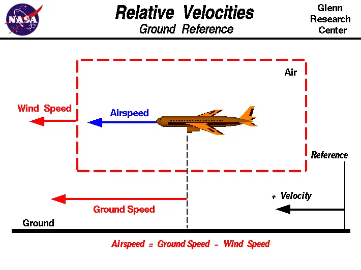
One of the most confusing concepts for young scientists is the relative velocity between objects. Aerodynamic forces are generated by an object moving through a fluid (liquid or gas). A fixed object in a static fluid does not generate aerodynamic forces. Hot air balloons "lift" because of buoyancy forces and some aircraft like the Harrier use thrust to "lift" the vehicle, but these are not examples of aerodynamic lift. To generate lift, an object must move through the air, or air must move past the object. Aerodynamic lift depends on the square of the velocity between the object and the air. Now things get confusing because not only can the object be moved through the air, but the air itself can move. To properly define the relative velocity, it is necessary to pick a fixed reference point and measure velocities relative to the fixed point. In this slide, the reference point is fixed to the ground, but it could just as easily be fixed to the aircraft itself. It is important to understand the relationships of wind speed to ground speed and airspeed.
Wind Speed
For a reference point picked on the ground, the air moves relative to the reference point at the wind speed. Notice that the wind speed is a vector quantity and has both a magnitude and a direction. Direction is important. A 20 mph wind from the west is different from a 20 mph wind from the east. The wind has components in all three primary directions (north-south, east-west, and up-down). In this figure, we are considering only velocities along the aircraft's flight path. A positive velocity is defined to be in the direction of the aircraft's motion. We are neglecting cross winds, which occur perpendicular to the flight path but parallel to the ground, and updrafts and downdrafts, which occur perpendicular to the ground.
Ground Speed
For a reference point picked on the ground, the aircraft moves relative to the reference point at the ground speed. Ground speed is also a vector quantity so a comparison of the ground speed to the wind speed must be done according to rules for vector comparisons.
Airspeed
The important quantity in the generation of lift is the relative velocity between the object and the air, which is called the airspeed. Airspeed cannot be directly measured from a ground position, but must be computed from the ground speed and the wind speed. Airspeed is the vector difference between the ground speed and the wind speed.
Airspeed = Ground Speed - Wind Speed
On a perfectly still day, the airspeed is equal to the ground speed. But if the wind is blowing in the same direction that the aircraft is moving, the airspeed will be less than the ground speed.
Que3:Why is it not recommended to use aircraft engine power to move it on the ground at Airport?
Ans>>
For movement on the ground, the aircraft uses its own engine power, which is called taxiing.
- Generally, most of the airplanes can move themselves in reverse manner by making use of reverse thrust technology. But in most of the practical cases, it is not possible because when airplanes start using reverse thrust it will consume lots of fuels as well as causes lots of noise, and also be hazardous for the people working nearby.
- Another reason for not using reverse thrust is that the jet blast might cause damage to the terminal building or equipment. Since the engine is also close to the ground it will blow off the sand and debris forward and then suck them into the engine, causing damage to the engine.
- Therefore, there are pushback trucks in the airport. A pushback truck lifts the front wheel of the aircraft, their role in most airports is to move the aircraft away from the parking spot onto the taxiways, which is called towing.
Que 4: How an aircraft is pushed to runway when its ready to take off?
Ans>>
Pushback is an airport procedure during which an aircraft is pushed backwards away from its parking position, usually at an airport gate by external power. Pushbacks are carried out by special, low-profile vehicles called pushback tractors or tugs.
Although many aircraft are capable of moving themselves backwards on the ground using reverse thrust (a procedure referred to as a powerback), the resulting jet blast or prop wash would cause increased noise, damage to the terminal building or equipment, and hurt airport staff due to high-speed debris. This debris would also be sucked into the engine, as it is in normal use, and cause excessive wear - a major cause of wear on aircraft engines is during ground use. A pushback is therefore the preferred method when ground-handling aircraft.
Pushbacks at busy aerodromes are usually subject to ground control clearance to facilitate ground movement on taxiways. Once clearance is obtained, the pilot will communicate with the tractor driver (or a ground handler walking alongside the aircraft in some cases) to start the pushback. To communicate, a headset may be connected near the nose gear.
Since the pilots cannot see what is behind the aircraft, steering is done by the pushback tractor driver and not by the pilots. Depending on the aircraft type and airline procedure, a bypass pin may be temporarily installed into the nose gear to disconnect it from the aircraft's normal steering mechanism.
Once the pushback is completed, the towbar is disconnected, and any bypass pin removed. The ground handler will show the bypass pin to the pilots to make it clear that it has been removed. The pushback is then complete, and the aircraft can taxi forward under its own power.
Takeoff is the phase of flight in which an aerospace vehicle leaves the ground and becomes airborne. For aircraft traveling vertically, this is known as liftoff.
For aircraft that take off horizontally, this usually involves starting with a transition from moving along the ground on a runway.
For light aircraft, usually full power is used during takeoff. Large transport category (airliner) aircraft may use a reduced power for takeoff, where less than full power is applied in order to prolong engine life, reduce maintenance costs and reduce noise emissions. In some emergency cases, the power used can then be increased to increase the aircraft's performance. Before takeoff, the engines, particularly piston engines, are routinely run up at high power to check for engine-related problems.
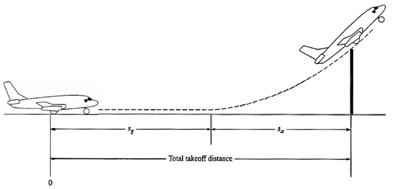
An airplane is motionless at the end of a runway. This is denoted by location O. The pilot releases the brakes and pushes the throttle to maximum takeoff power, and the airplane accelerates down the runway. At some distance from its starting point, the airplane lifts into the air. The distance the airplane cover along the runway before it lifts into the air is called the ground roll (sg). The total takeoff distance also includes the extra distance covered over the ground after the airplane is airborne but before it clears an obstacle of 50 ft for military aircraft and 35 ft for commercial aircraft. This is denoted by sa. The sum of sg and sa is the total takeoff distance.
Tyre Design:
An aircraft tyre is designed to withstand extremely heavy loads while landing, take off, taxing, and parking. The number of wheels required for aircraft increases with the weight of the aircraft, as the weight of the aeroplane needs to be distributed more evenly. For example - A Boeing 737NG & 737MAX uses 6 wheels, Boeing 787 uses 10 wheels, Boeing 777 uses 14 wheels and Airbus A380 uses 22 wheels.
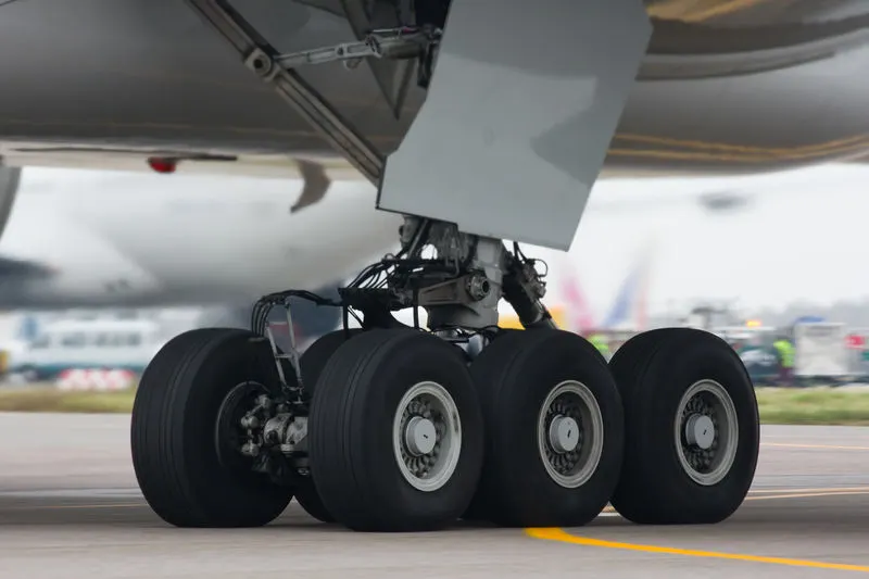
Fig: Tires on the wheels of a bogie on a Boeing 777
Aircraft tires also include fusible plugs (which are assembled on the inside of the wheels), designed to melt at a certain temperature. Tires often overheat if maximum braking is applied during an aborted takeoff or an emergency landing. The fuses provide a safer failure mode that prevents tire explosions by deflating in a controlled manner, thus minimizing damage to aircraft and objects in the surrounding environment.
Designing aircraft tires is a very intense undertaking. Carcass plies are used to form the tire. They are sometimes called casing plies. An aircraft tyre is constructed for the purpose it serves.
- They support the weight of an aircraft while it is on the ground.
- It also provides the necessary traction for braking and stopping of an aeroplane.
- Tyre also helps to absorb the shock of landing and provide cushioning the roughness of takeoff, roll-out, and taxi operations.
Rolling Resistance:
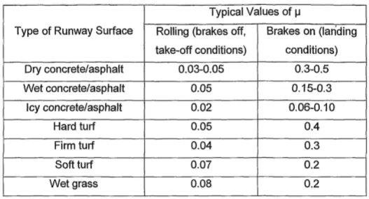
- In addition to the familiar forces like thrust, weight, lift, drag there is a rolling resistance force FR caused by friction between tyre and ground. When aircraft is towing or taxiing to push it into the runway or when takeoff roll is happening, the rolling resistance force act against the traction force of the aircraft.
- This rolling resistance force depends on many factors like surface of the road, roughness of the road, dry or wet condition of the road, tyre pressure, tyre material, tyre temperature, thread pattern of the tyre etc, which determines the rolling resistance force.
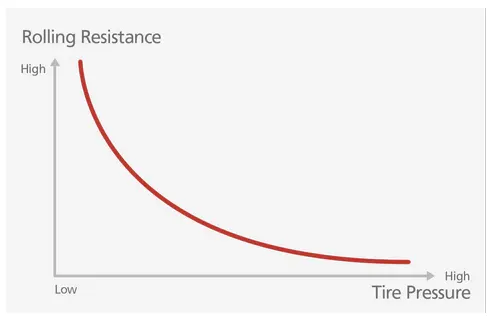
- The rolling resistance coefficient is denoted by μrr">μrrμrr. The values vary with speed. Tire pressure increases its value decreases need to carefully choose value as per typical cases under consideration.
Rolling Resistance force (Frr)">(Frr)(Frr) = μrr">μrrμrrx m x g
Where,
μrr">μrrμrr= Rolling resistance coefficent
m = Total mass of the aircraft in kg
g = Gravitational constant i.e, 9.8 m/s2">s2s2
Tyre Pressure:
Aircraft tires may be tube-type or tubeless. Tubeless tyres are more advantageous over tube-type. There is no longer the use of tube-type tyre in recent aviation. Nowadays all airliners are using tubeless tyres. Tubeless that are meant to be used without a tube has the word TUBELESS on the sidewall of the tyre.
Tyre pressure varies from plane to plane.
- The tires do not use the typical compressed air we would use from a fuel station supply or a home air compressor.
- Aviation tires are made of a much stronger compound than what we use for the auto industry and in fact, they use nitrogen gas to inflate the tires, as opposed to compressed air.
- This provides additional strength to the tires in general, to support the tremendous weight they carry moving the plane or on take-off and for landing.
- The average pressure they run in the tires is between 200-220 PSI, it again depends on the model aircraft(Automobile run 30-40 PSI on average).
- Tires are required to replace after every 300 or so cycles. A cycle represents 1 for a landing and 1 for a lift-off. Every time a plane lands and departs, this is considered 2 cycles.
- When the tire pressure becomes too low then values of rolling resistance increase too much.
Brake forces when landing:
Even though airplanes have become one of the most convenient ways of traveling in the modern world, there are very few people who are aware of how it operates. As we all know, when a plane is about to land, it is at high speed, typically 16 mph. The question here is that how can a plane de-accelerate safely, even though it is coming at such a high speed?
To understand the answer to this question, we have to understand how braking works, not just in an airplane, but in any vehicle which has wheels. As we have already mentioned above how the braking process exerts torque on the wheels due to which friction is produced. As a result, friction is produced with the ground, and it loses kinetic energy, and hence, the vehicle stops.
But the thing about friction is that it depends entirely on the weight of the vehicle. In the case of the airplane, when it is landing, the aerodynamic lift renders the weight of the plane zero, and hence, the brakes on the wheels are pretty much inefficient to stop the plane. That is why the plane needs to find other ways to stop until both the aerodynamic lift and the speed has reached a sufficient stage. Modern aircraft use several different braking systems to do this:
Wing Spoilers:
Many airplanes use wing spoilers to assist with braking when landing. Not to be confused with ailerons, spoilers are extendable flaps on the ends of an airplane’s wings. Pilots can raise the spoilers to decelerate the airplane as it approaches the runway. And even while on the runway, pilots will typically leave the wing spoilers raised. Raised wing spoilers create the drag, which essentially slows down the airplane so that it’s able to brake more quickly.
Aircraft Disc Brakes:
In addition to wing spoilers, airplanes use disc brakes. Airplane disc brakes are similar to the braking system in automobiles. They consist of a pair of calipers that, when engaged, squeeze pads against the rotors of an airplane’s landing gear.
Disc brakes are designed to remain static at all times. In other words, they don’t rotate with the wheels of an airplane’s landing gear. As the wheels turn, the disc brakes will remain static and stationary. They are a vital component of an airplane’s braking system because they are designed to apply pressure to the airplane’s wheels. Disc brakes will squeeze the wheels, thereby slowing down the speed at which they spin. In turn, this reduces the speed of the airplane so that it can come to a complete stop on the runway.
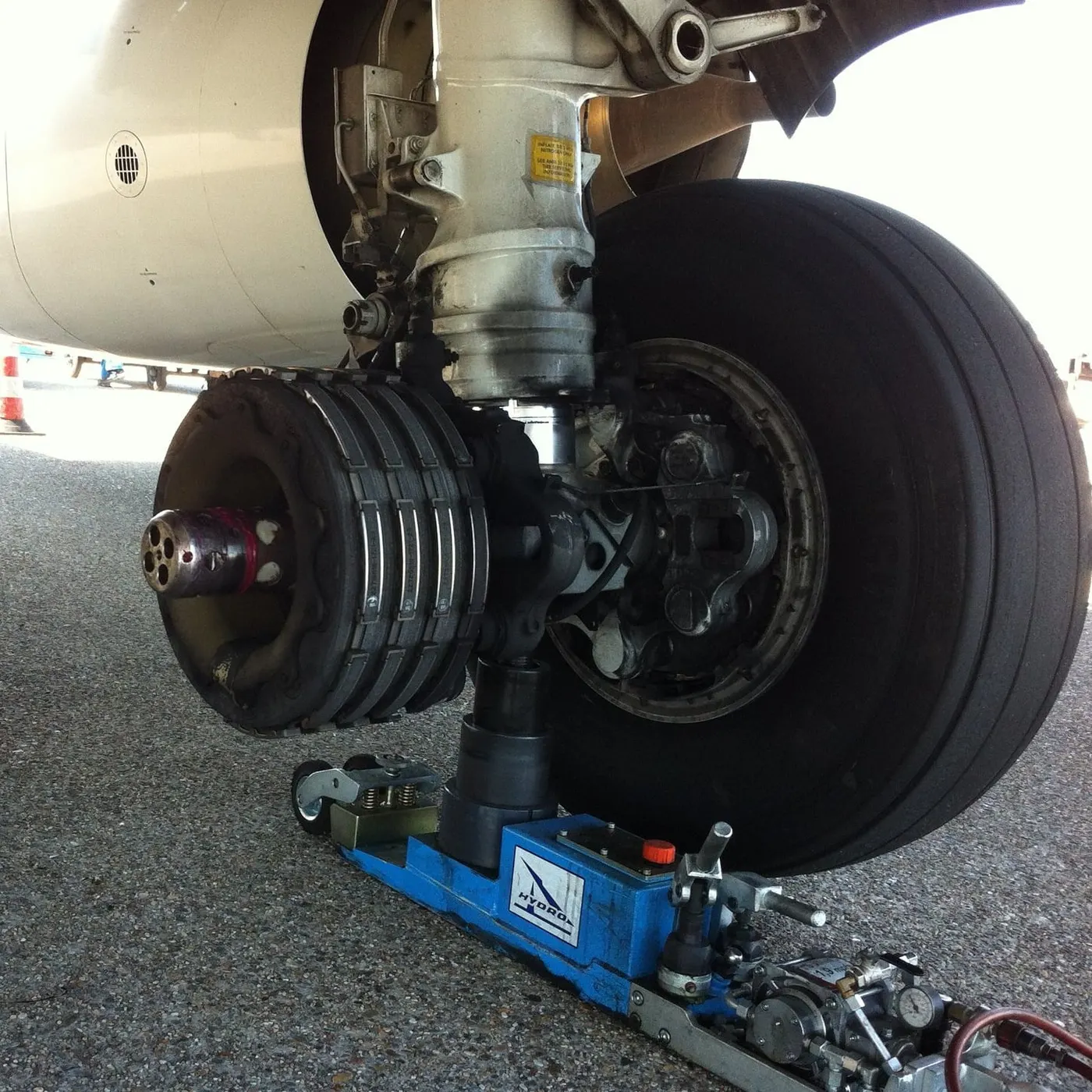
Fig: A brake assembly on a Boeing 737NG main landing gear
Reverse Thrust:
Many jet airplanes use reverse thrust to assist with braking during landings. Reverse thrust is a feature in jet engine airplanes that, as the name suggests, involves the reversal of the engines’ thrust. When flying, the thrust is projected out the rear of an airplane’s engines. When landing, however, pilots may use the reverse thrust feature. Reverse thrust changes the direction of the engines’ thrust. Rather than projecting out the rear, the thrust will be projected out the front. This reversal of thrust provides deceleration that allows airplanes to slow down more quickly when landing.
Part B
Que 6:
A. With necessary assumptions, calculate the force and power required to push / pull an aircraft by a towing vehicle.
Ans>>
Assumptions:
Total mass of ther aircraft (including payload): 180000 kg
Coefficient of Rolling Resistance(Crr) = 0.02
Drag coefficient(Cd): 0.25
Air Density (ρ) = 1.225 kg/m^3
Frontal Area of the vehicle (A) = 150^2
Speed of the Vehicle (V) = 18kmph or 5m/s
Rolling Resistance(Frr):
Coefficient of Rolling Resistance(Crr) = 0.02
Rolling Resistance Force(Frr) = Crr*m*g
Frr = 0.02*180000*9.8 = 35,280N
Aerodynamic Resistance(Fd):
Drag coefficient(Cd): 0.25
Air Density (ρ) = 1.225 kg/m^3
Frontal Area of the vehicle (A) = 150^2
Speed of the Vehicle (V) = 18kmph or 5m/s
Fd = 1/2*Cd* ρ *A*v^2 = 1/2*0.25*1.225*150*5^2 =574.22N
Total Force:
Frr + Fd = 35280 + 574 = 35854.22
Power Calculation:
Total force* V = 35854.22*5 = 179271.1W = 179.2kW
Power Required for Pull/Push Aircraft is 179.2 kW
B. Develop the model for the calculated force and power using Simulink.
Ans>>
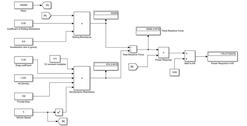
Model Develop for Power calculation of Aircraft as shown below:
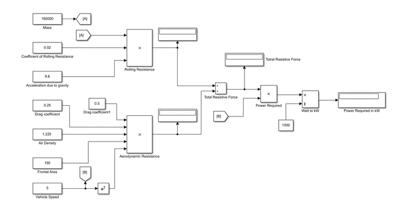
Steps follows during developing model:
Step 1:
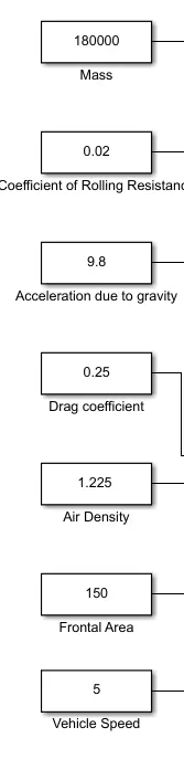
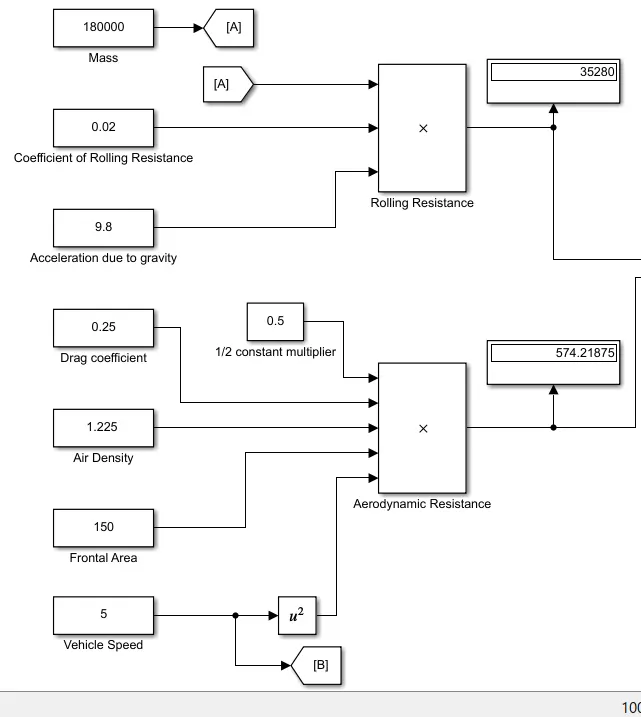
created constant for assumption parameters which are :
1. Mass
2.Coefficient of Rolling Resistance
3.Acceleration due to gravity
4. Drag coefficient
5. Air Density
6.Frontal Area
7. Vehicle Speed
Step 2: Calculated forces using this constants as shown below
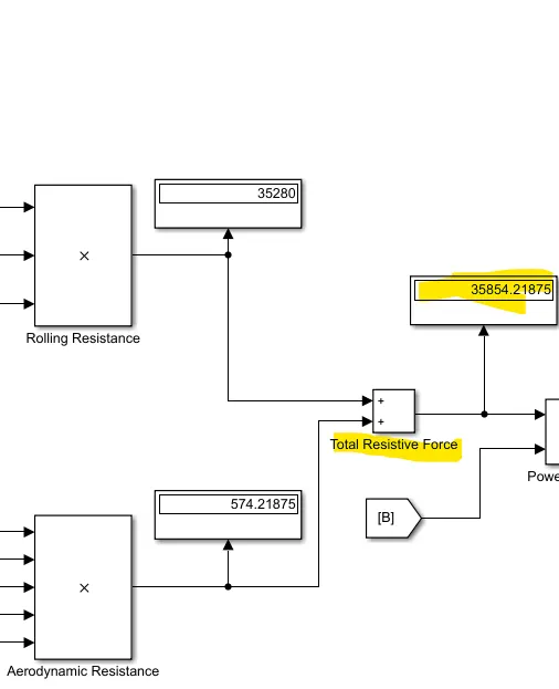
Step 3: Calculated total force using sum block
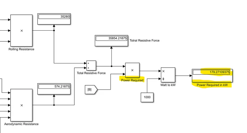
Step 4: Power is calculated Using vehicle speed in m/s and total forces as shown below
Step 2: Complete Results of Power caculation for aircraft model is as shown below
Que 7:
A. Design an electric powertrain with type of motor, it’s power rating, and energy requirement to fulfill aircraft towing application in Simulink. Estimate the duty cycle range to control the aircraft speed from zero to highest. Make all required assumptions. Prepare a table of assumed parameters. Draw a block diagram of powertrain.
Ans>
Block Diagram of Electric Powertrain:
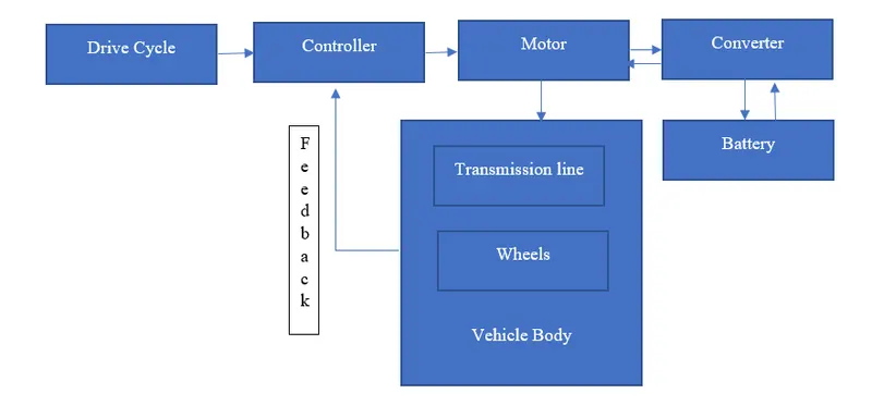
Calculations of Duty Cycle required for Control
Based on 6th Example:
Force required to pull/push the Aircraft = 35.280 kN
And Power Required = 179.2kW
Assumptions:
Radius of Tyre of Tug = 0.65m
Gear Ratio = 8
Transmission efficiency (nt) = 90%
Motor Efficiency (nm) = 92%
Then,
Torque required for wheels to (Tw) = Total force* Radius in meter = 35.208*0.65= 22.8852
Therefore,
Motor Torque = Wheel torque/ (Gear ratio*Transmission Efficiency)
= 22.8852/ (8*0.9) = 3.1785 kNm
Thus, for motor efficiency nm =92%,
Required motor torque (Tm)= 3.1785 /0.92=3.454kNm
Similarly,
Total required power by the motor considering all efficiencies(pt)=179.2/ (0.90*0.92) = 216.42512 kw
Assume operation for 30min(0.5hr) duration,
Energy consumed =216.42512 *0.5 =108.21kwh
Consider Battery capacity = 270kw is used by towing vehicle
then the duty cycle range to control the speed from 0 to max speed(5m/s) is given as
Duty Cycle= Required power/ Rated power= 216.42512/270=0.8
Therefore, the controller will be able to provide a duty cycle ranging from 0 to 80% in order to control the towing speed.
Simulink Model:
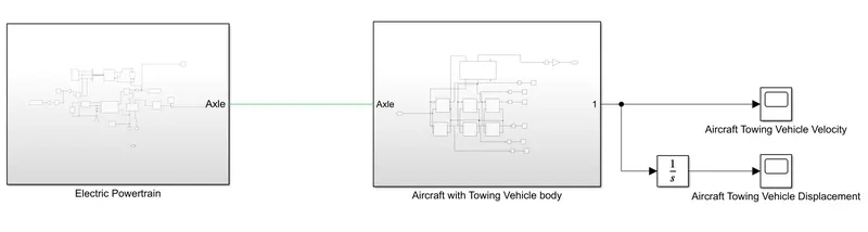
Aircraft powertrain model develop as shown below:
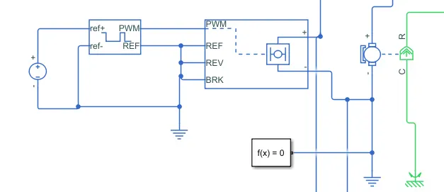
Step 1: Electric Motor and Its controller is design using H bridge, PWM voltage controller and DC motor as shown below
Assumption in DC motor paramerts : Torque =2500Nm and No load Speed =840RPM
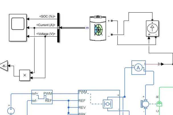
Step 2: Current consumed by DC motor is given to battery for SOC calculation
Assumption of battery paramerts: Voltage=230 V, Capacity=1000 Ah
Step 3: Torque output of DC motor is connected to gear box of 8 ratio and inertia of 0.001 kg*m^2
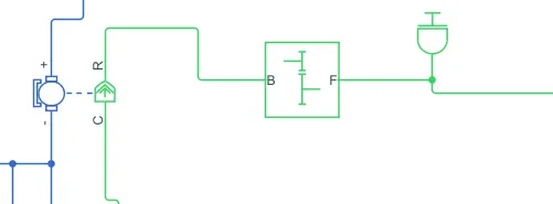
Step 4: After gear box this is connected to axle of vehicle, then it is connected to rear wheel of aircraft with radius of 0.65m
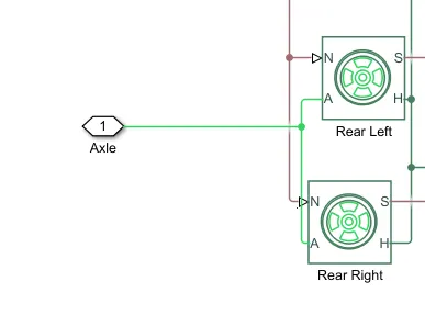
Step 5: Vehicle body and wheel connections of aircraft using simscape library is as shown below
Assumption of Vehicle body paramerts are: Vehicle mass=180000 kg, Frontal area=150 m^2, Drag Coefficient =0.25
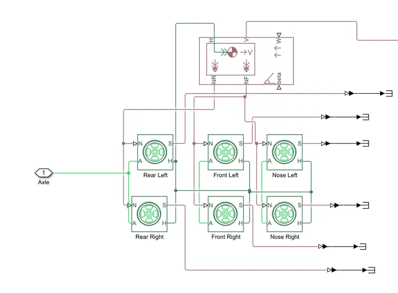
Step 6: Output of this model is Aircraft velocity and displacement
Results> In 30 sec ATS is able to tow aircraft to 55m
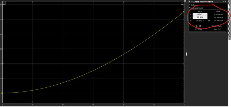
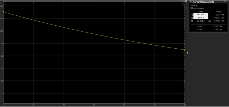
Power Required during Towing of aircraft is as shown below in which 130 kW required intitally then it reduced to 70 kW
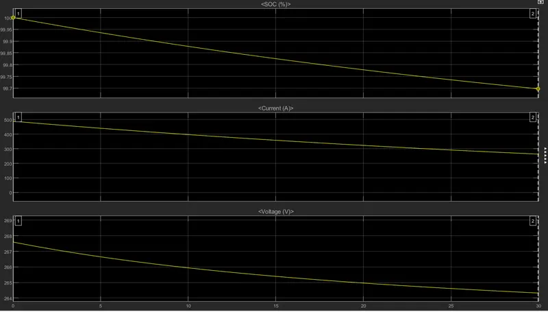
Effect on Battery Paramers during intial Towing of Aircraft is as shown below:
Battery SOC drop from 100 to 99.7% with Intial Current of 500 A
B.Also, Design the parameters in excel sheet.
>>
Parmerts Design in Excel sheet as shown below:
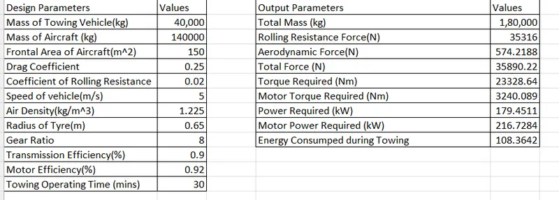
In this excel sheet all Design parameters are mentioned in 1st table and all calculated parameters of reference example 6 are mentioned in 2nd table
This excel sheet can be used for aircraft towing vehicle designing
Excel sheet attached for reference