Project-1: Powertrain for aircraft in runways
Part A:
1.
Aircraft Gross Weight:
- The aircraft's gross weight is the total aircraft weight at any moment during the flight or ground operation. An aircraft's gross weight will decrease during a flight due to fuel & oil consumption. An aircraft's gross weight may also vary during a flight due to payload dropping or in-flight re-fuelling.
- At the moment of releasing its brakes, the gross weight of an aircraft is equal to its takeoff weight. During the flight, an aircraft's gross weight is referred to as the in-flight weight.
-
Several weight restrictions limit an aircraft's gross weight to avoid overloading its structure or unacceptable performance or handling qualities while in operation.
-
Aircraft gross weight limits are established during an aircraft's design and certification period and are laid down in the aircraft's type certificate and manufacturer specification documents.
-
A given aircraft's absolute maximum weight capabilities are referred to as the structural weight limits. The structural weight limits are based on the aircraft's full structural capability and define the envelope for the CG charts (both maximum weight and CG limits).
-
An aircraft's structural weight capability is typically a function of when the plane was manufactured. In some cases, old aircraft can have their structural weight capability increased by structural modifications.
- Maximum Design Taxi Weight (MDTW): The maximum design taxi weight is the maximum weight certificated for aircraft manoeuvring on the ground (taxiing or towing) as limited by aircraft strength and airworthiness requirements.
- Maximum Design Takeoff Weight (MDTOW): It is the maximum certificated design weight when the brakes are released for takeoff and is the most significant weight for which the manufacturer has demonstrated compliance with the relevant structural and engineering requirements.
- Maximum Design Landing Weight (MDLW): The maximum certificated design weight at which the aircraft meets the appropriate landing certification requirements. It generally depends on the landing gear strength or the landing impact loads on certain parts of the wing structure. The MDLW must not exceed the MDTOW. The maximum landing weight is typically designed for 10 feet per second (600 feet per minute) sink rate at touch down with no structural damage.
- Maximum Design Zero-Fuel Weight (MDZFW): The maximum certificated design weight of the aircraft less all usable fuel and other specified usable agents (engine injection fluid, and other consumable propulsion agents). The maximum weight is permitted before usable fuel and other selected usable fluids are loaded in specified aeroplane sections. The MDZFW is limited by strength and airworthiness requirements. At this weight, the subsequent fuel addition will not result in the aircraft design strength being exceeded. The weight difference between the MDTOW and the MDZFW may be utilised only for the addition of fuel.
- Minimum Flight Weight (MFW): Minimum certificated weight for flight as limited by aircraft strength and airworthiness requirements.
| Aircraft Model | MTOW (lb) | MTOW (kg) |
| Airbus A318 | 149,900 | 67993.4963 |
| Airbus A319 | 166,400 | 75477.7704 |
| Airbus A320 | 172,000 | 78017.8876 |
| Airbus A321 | 206,100 | 93440.0282 |
| Airbus A330-200 | 529,100 | 239995.723 |
| Airbus A330-200F | 514,000 | 233146.478 |
| Airbus A330-300 | 529,100 | 239995.723 |
| Airbus A340-300 | 609,000 | 276237.753 |
| Airbus A340-600 | 837,800 | 379656.814 |
| Airbus A350-900 | 617,300 | 280002.57 |
| Airbus A350-1000 | 681,000 | 308896.404 |
| Airbus A380 | 1,268,000 | 575155.1252 |
| Boeing 737-700 | 154,500 | 70080.0212 |
| Boeing 737-800 | 174,200 | 79015.7909 |
| Boeing 737-900ER | 187,700 | 85139.2878 |
| Boeing 747-400 | 875,000 | 396893.324 |
| Boeing 747-400F | 875,000 | 396893.324 |
| Boeing 747-8I | 987,000 | 447695.669 |
| Boeing 757-200 | 255,000 | 115666.054 |
| Boeing 757-300 | 272,500 | 123603.921 |
| Boeing 767-300ER | 412,000 | 186880.056 |
| Boeing 767-400ER | 450,000 | 204116.567 |
| Boeing 777-200ER | 656,000 | 297556.595 |
| Boeing 777-200LR | 766,000 | 347451.755 |
| Boeing 777-300ER | 775,000 | 351534.087 |
| Boeing 777F | 766,800 | 347814.629 |
| Boeing 787-8 | 502,500 | 227930.166 |
| Boeing 787-9 | 560,000 | 254011.727 |
| Boeing 787-10 | 560,000 | 254011.727 |
| Bombardier CRJ100ER/LR | 53,000 | 24040.396 |
| Bombardier CRJ200ER/LR | 53,000 | 24040.396 |
| Bombardier CRJ700ER | 75,000 | 34019.428 |
| Bombardier CRJ900ER/LR | 82,500/84,500 | 37421.371/38328.555 |
| Bombardier CRJ1000ER | 91,800 | 41639.78 |
| Embraer 170LR | 82,000 | 37194.574 |
| Embraer 175 | 85,520 | 38791.219 |
| Embraer 190 | 110,900 | 50303.3938 |
| Embraer 195 | 111,970 | 50788.7377 |
2.
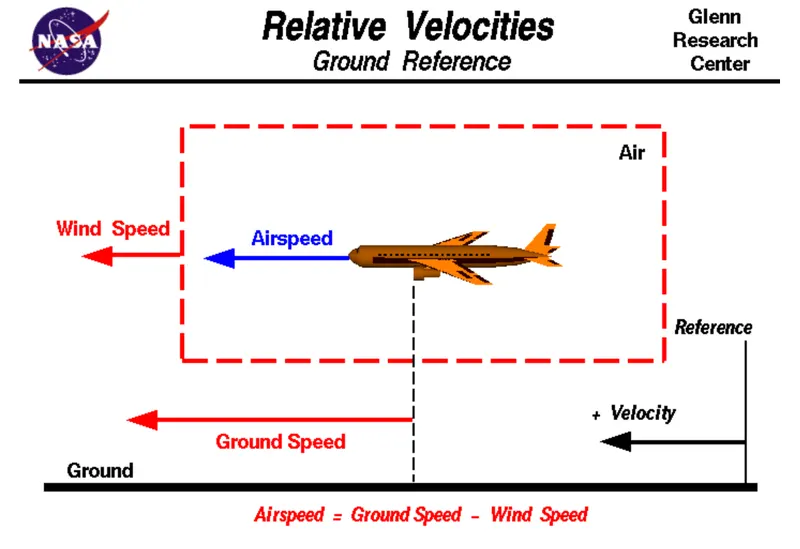
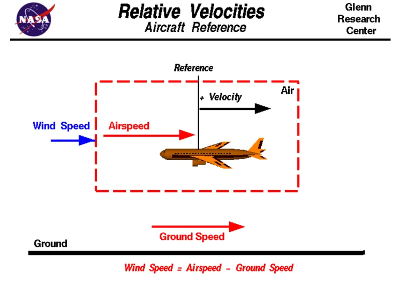
- While ground speed is the aeroplane's speed relative to the surface of the Earth, airspeed is its speed relative to the air it is flying in.
- True airspeed is simply the speed at which an aircraft is moving relative to the air it is flying in. It is also the speed at which the air flows around the aircraft's wings.
- Ground speed, on the other hand, is the aircraft's speed relative to the ground. It's horizontal rather than vertical speed - an aircraft climbing completely vertically would have a ground speed of zero.
- While airspeed determines whether there is enough airflow around an aircraft to make it fly, ground speed determines how fast an aircraft will get to its destination.
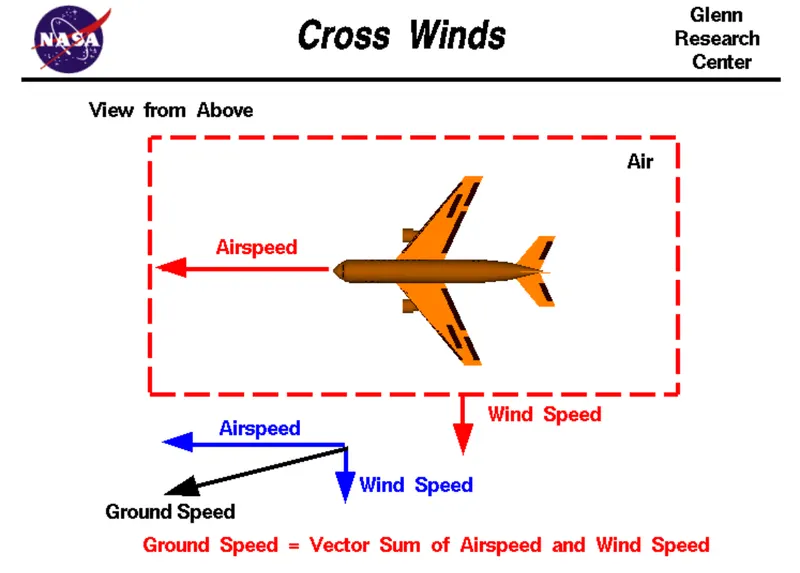
- The relationship between airspeed and ground speed is pretty simple. Ground speed is the sum of airspeed and wind speed.
- If the aircraft is flying in the same direction as the wind is blowing, it experiences a tailwind, and its ground speed is higher than its airspeed. On the other hand, if the wind is blowing against the direction the aircraft is travelling in, the aircraft experiences a headwind, and its ground speed is lower than its airspeed.
For example:
- An aircraft that cruises at an airspeed of 500 miles per hour has to cover a ground distance of 2,000 miles.
- If there is no wind, then the aircraft’s airspeed and ground speed would be the same at 500 miles per hour, and the plane would reach its destination in four hours.
- If there were a 100 miles per hour headwind – wind blowing against the aircraft’s direction of travel – the plane would still be travelling at an airspeed of 500 miles per hour. However, its ground speed would be just 400 miles per hour (100 miles per hour slower than its airspeed). And as such, it would take the aircraft five hours to reach its destinations.
- Finally, if there were a 100 miles per hour tailwind – wind blowing in the same direction as the aircraft’s travel – the plane would still be travelling at an airspeed of 500 miles per hour, but its ground speed would be 100 miles faster. And, at 600 miles an hour, the aircraft would reach its destination in just 3 hrs 20 mins.
3. It is not recommended to use aircraft engine power to move it on the ground at Airport because of the following reasons:
- Aeroplane Structure
- Flight Controls
- Equipment & personnel
Let us consider an example.
a. Aeroplane Structure:
- In an incident related to Foreign Object Damage (FOD) caused by high engine thrust, Boeing was informed that a 737 had landed at a European airport and the flight crew had discovered significant damage during their walkaround inspection.
- Damaged areas included the right horizontal stabilizer leading edge and lower surface and elevator lower surface.
- Upon inspection, a bricklike paving material was found embedded within the stabilizer structure.
- Shortly before the FOD was identified, the Boeing Field Service representative at the originating airport was notified of runway threshold damage.
- The subsequent correlation of these events matched the brick paving material extracted from the aeroplane with identical material formerly located along the runway threshold.
- The engine exhaust lifted the paving material and blew aft as the aeroplane turned onto the runway for takeoff.
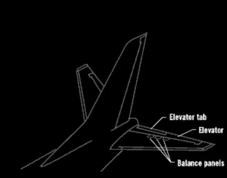
- The repair included the replacement of the stabilizer, elevator, elevator tab, and stabilizer-to-body closure panels.
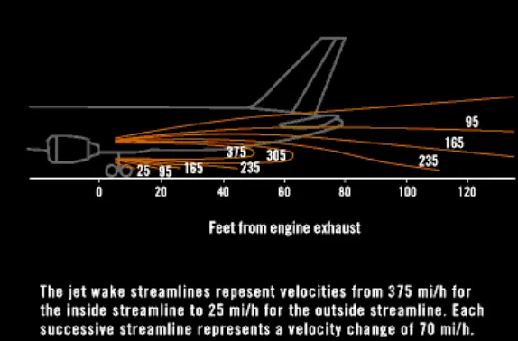
b. Flight Controls:
-
FOD can also affect flight control system component interaction and system displacement force, which is intimately related to properly functioning primary control surfaces.
-
In most aeroplanes, the elevator is powered by independent hydraulic systems through power control units.
-
Some aeroplanes offer other modes that allow manual elevator operation.
-
In an unpowered mode, aerodynamic balance panels, linkages, and hinges interact to assist in elevator deflection against air loads.
-
These elements must work together to ensure that actual elevator displacement is proportional (and repeatable) concerning the control column displacement, thereby providing a consistent pitch response.
-
This interrelationship of proportional response is sufficiently important that aviation regulatory agencies impose certification requirements prohibiting aeroplane response reversal and requiring aeroplane pitch response to be proportional to control column displacement.
Even subtle FOD to the external portions of the elevator can change the surface balance and alter the airflow characteristics, which may induce surface flutter.
-
This dynamic and uncommanded surface movement can grow in amplitude and frequency, causing additional damage.
-
The violence of the induced motion may destroy portions of the surface.
-
If this motion is great enough, it can be coupled to a nearby aeroplane structure and cause collateral damage.
-
In exceptional cases, control surface flutter could lead to loss of aeroplane control.
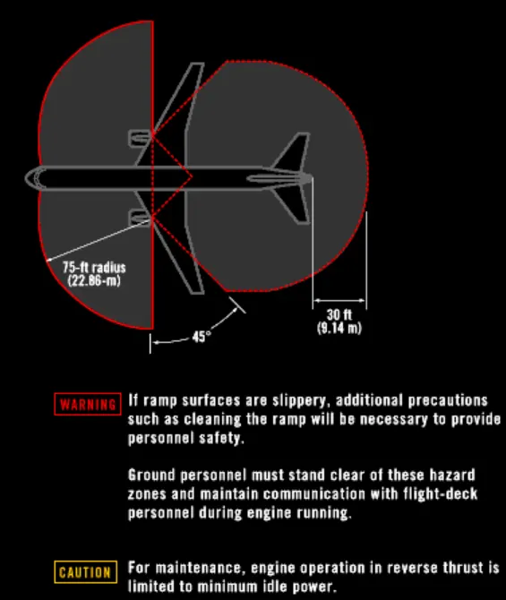
c. Equipment & personnel:
- FOD also has the potential to affect many aspects of ramp operations.
- These operations subject people, baggage carts, service vehicles, and airport infrastructure to injury and damage.
- For example, unsecured baggage carts can be displaced by the exhaust of passing aeroplanes, causing aeroplane damage or injury to personnel.
- Engine inlets represent a potential personnel ingestion hazard.
- Aeroplane reverse-thrust operations and the use of reverse thrust to move an aeroplane will increase the power hazard area and require particular care to ensure that people and equipment are adequately protected.
4.
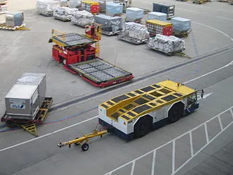
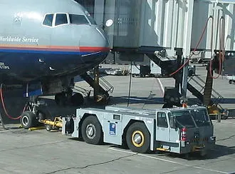
- Pushback is an airport procedure during which an aircraft is pushed backwards away from its parking position, usually at an airport gate by an external power.
- Pushbacks are carried out by special, low-profile vehicles called pushback tractors or tugs.
- Pushbacks at busy airports are usually subject to ground control clearance to facilitate ground movement on taxiways.
- Once clearance is obtained, the pilot will communicate with the tractor driver to start the pushback. To communicate, a headset may be connected near the nose gear.
- Since the pilots cannot see what is behind the aircraft, steering is done by the pushback tractor driver and not by the pilots.
- Depending on the aircraft type and airline procedure, a bypass pin may be temporarily installed into the near gear to disconnect it from the aircraft's normal steering mechanism.
- Once the pushback is completed, the towbar is disconnected, and a bypass pin is removed.
- The ground handler will show the bypass pin to the pilots to clarify that it has been removed.
- The pushback is complete, and the aircraft can taxi forward under its power.
5.
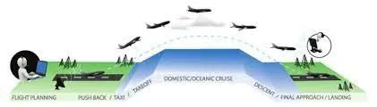
i. Take-off Power: Most take-offs use derated thrust to save engine wear. For each take-off, performance is calculated, the necessary power setting is determined and the thrust setting is made. The reduced power or derated take-offs are typical and frequently used. The performance is carefully calculated before each take-off, ensuring that the proper speeds, power settings and flaps are used for the weight of the take-off on the runway intended and at the appropriate temperature. When using this method during take-off, it is always possible to increase to full power if the situation requires it. The captain always decides whether to use full thrust or derate.
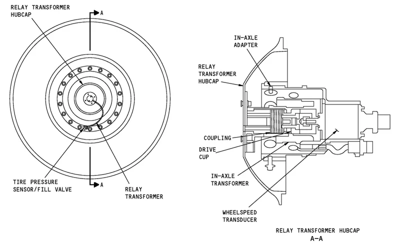
ii. Tyre Design: An aircraft tyre is designed to withstand extremely heavy loads for short durations. The number of tires required for aircraft increases with the weight of the plane, as the weight of the aeroplane needs to be distributed more evenly. Aircraft tire tread patterns are designed to facilitate stability in high crosswind conditions, to channel water away to prevent hydroplaning, and for braking effect. Aircraft tires also include fusible plugs (which are assembled on the inside of the wheels), designed to melt at a specific temperature. Tires often overheat if maximum braking is applied during an aborted takeoff or an emergency landing. The fuses provide a safer failure mode that prevents tire explosions by deflating in a controlled manner, thus minimizing damage to aircraft and objects in the surrounding environment.
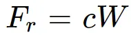
iii. Rolling resistance: The force that resists the motion of a body rolling on a surface is called the rolling resistance. The generic equation can express the rolling resistance:
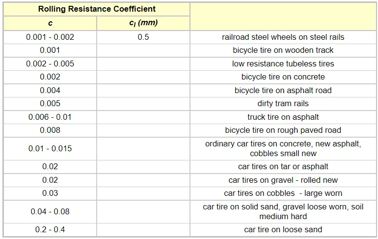 iv. Tyre pressure: The high-flying rubber is typically inflated to 200 psi, roughly six times what you put in an automobile tire, and the tires on an F-16 fighter are pumped to 320 psi.
| Aeroplane | Tyre Pressure (psi) |
| B727-200 | 148 |
| B737-300 | 195 |
| A319-100 | 196 |
| B747-400 | 200 |
| B767-300ER | 190 |
| DC8-63 | 194 |
| A300-B4 | 205 |
v. Brake force: The brake units are powered by the hydraulics system. An electrical signal is sent from the flight deck to hydraulic actuators near the main landing gear. Here, hydraulic fluid at 3,000 pounds per square inch is used to force the brake unit against the wheel, thus slowing it down.
Part B
6.
A. The force to move an aeroplane on a flat runway with no wind at a constant low speed equals the rolling resistance between the plane and the tarmac.
The rolling resistance force for the aeroplane can be calculated as
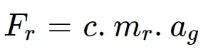
where Fr = Rolling resistance (N)
c = Rolling resistance coefficient
mr = Rolling mass (kg, lb)
ag = Gravitational acceleration ( = 9.81 m/s2)
The aerodynamic drag force caused by the aircraft and the towing vehicle can be given by the equation below:

where
A = Frontal area of the vehicle in m2
ρ = Air density ( = 1.25 kg/m3)
Cdt = Air drag coefficient of the towing vehicle (it depends on the frontal area, shape, protrusions, ducts, air passage etc.)
Cda = Air drag coefficient of aircraft (It depends on the frontal area, shape, protrusions, ducts, air passage etc.)
v = Velocity of the vehicle in m/s
The hill climbing force is the force needed to move the vehicle up-gradient. The expression of the equation is given below:

where m = Total mass of the vehicle (Vehicle mass + Payload) in kg
ag = Gravitational acceleration ( = 9.81 m/s2)
ϕ = Up-gradient angle or inclination angle (degree)
Linear Acceleration Force reflects a change of speed in a straight line. This acceleration occurs during take-off, landing, or level flight when a throttle setting is changed. The expression of the equation is given below:
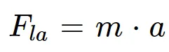
where m = Total mass of the vehicle (Vehicle mass + Payload) in kg
a = Acceleration of the vehicle
Angular acceleration results from a simultaneous change in both speed and direction, which happens in spins and climbing turns. The expression of the equation is given below:
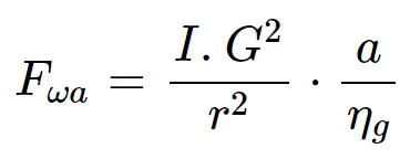
where I = Moment of inertia (kg/m2)
G = Gear ratio
r = Radius of the wheel
ηg = Transmission efficiency
Let us consider an example.
Force required to push/pull an aeroplane at constant low speed on the tarmac.
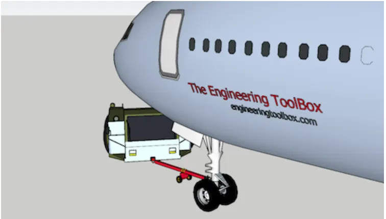
If the mass of a plane is 183,700 kg and the towing mass of the vehicle is 50,000 kg, the total mass of the vehicle is (50,000 + 183,700 = ) 233,700 kg.
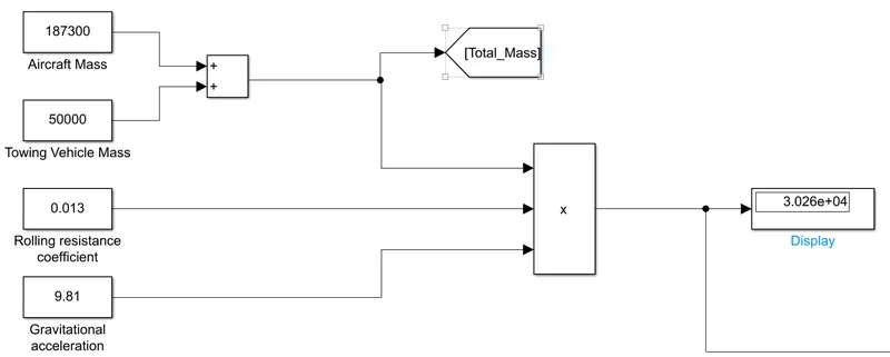
Let us assume the rolling resistance coefficient to be 0.013. So, the Rolling Resistance force of the aircraft is 29803.761 N.

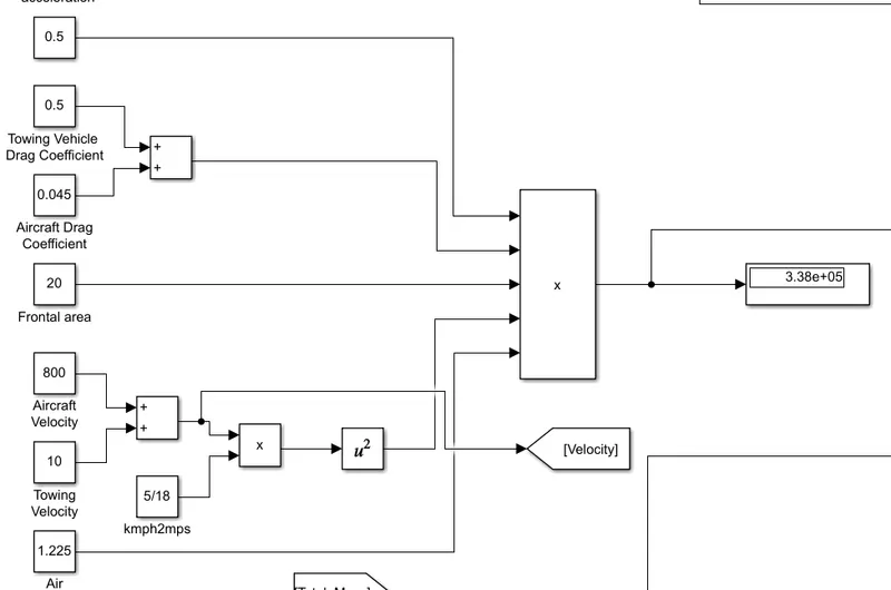
Let us assume that the air density is 1.225 kg/m3, and the drag coefficient for Towing Vehicles & Aircraft is 0.5 & 0.045 respectively. The aircraft is running at a speed of 500 miles per hour (or 800 kmph). The frontal area of the aircraft is assumed to be 20 m2. Therefore, the Air Drag Force is 3,37,985.1563 N.

In this case, the up-gradient angle (ϕ) = 0, as there is no inclination. Therefore, Hill Climbing Force is 0 N.
Let us assume the moment of inertia of the motor is 0.076 kg m2. The radius of the towing wheel is 15 inches (= 0.38 m) and that of the aircraft wheel is 27 inches (= 0.68 m). The gear ratio is assumed to be 8. The transmission efficiency is 87%. The Towing vehicle takes 2 mins to push/pull the aeroplane to the runway and the aircraft takes approximately 5 mins to take off/land.
The Linear Acceleration Force of the aircraft is:

and the Angular Acceleration Force of the aircraft is:

Now the Total Force of the vehicle is:
Total force = Frr + Fad + Fhc + Fla + Fwa
= 29,803.761 + 3,37,985.1563 + 0 + 1,25,196.4286 + 6.88
= 4,92,992.2259 N
and the power required to push/pull an aircraft by a towing vehicle is:
Total power = Total Force * Velocity
= 4,92,992.2259 * 810
≈ 400 MW
B.
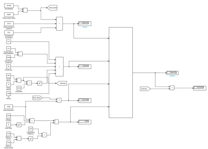
The above calculation is developed in the below Simulink:
Rolling Force
Aerodynamic Drag Force
Acceleration Force
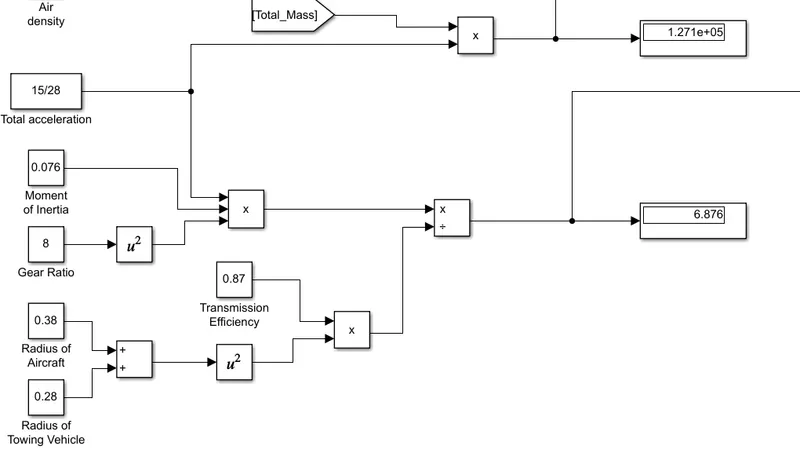
Total Traction Force and Power
7.
A.
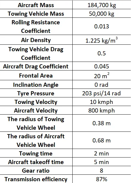
| Aircraft Mass | 184,700 kg |
| Towing Vehicle Mass | 50,000 kg |
| Rolling Resistance Coefficient | 0.013 |
| Air Density | 1.225 kg/m3 |
| Towing Vehicle Drag Coefficient | 0.5 |
| Aircraft Drag Coefficient | 0.045 |
| Frontal Area | 20 m2 |
| Inclination Angle | 0 rad |
| Tyre Pressure | 203 psi/14 rad |
| Towing Velocity | 10 kmph |
| Aircraft Velocity | 800 kmph |
| The radius of Towing Vehicle Wheel | 0.38 m |
| The radius of Aircraft Vehicle Wheel | 0.68 m |
| Towing time | 2 min |
| Aircraft takeoff time | 5 min |
| Gear ratio | 8 |
| Transmission efficiency | 87% |
The Simulink model is shown below:
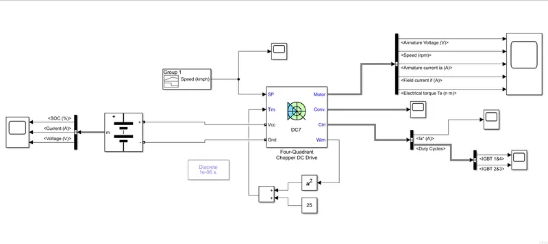
In this model, we have used Battery, Signal Builder, Four-Quadrant Chopper DC Drive, Math Function, Constant, Add, Bus selector and Scope blocks.
- The battery and the Four-Quadrant Chopper DC Drive are set to default. No changes are given.
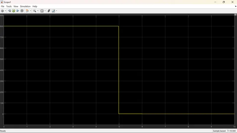
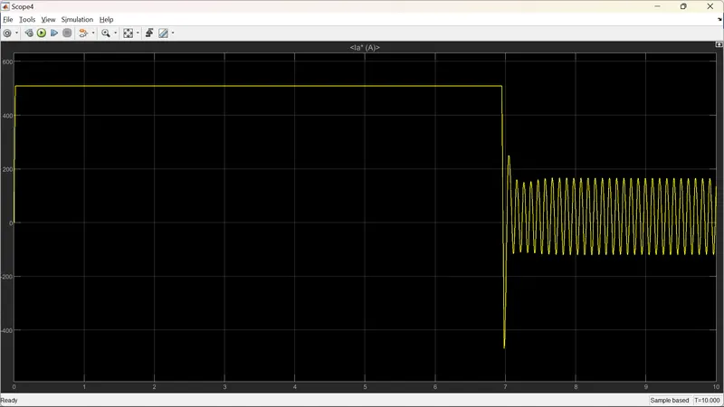
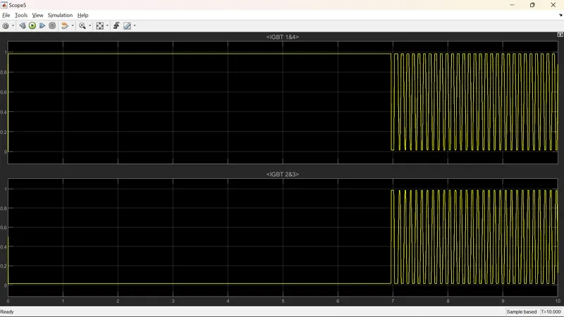
- The signal builder is set to a Step response, wherein the first-half simulation speed is constant at 800 kmph and in the second-half simulation, the speed is reduced to 0.
- Using Square law, the Wm is squared and added to a constant of 25 to provide Torque (Tm).
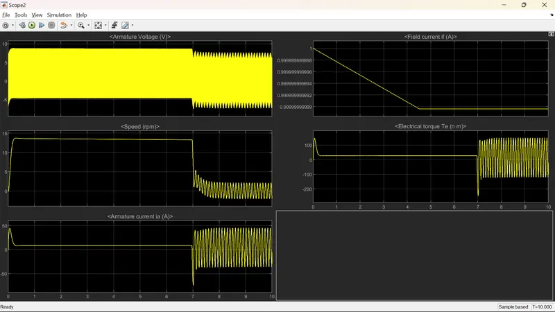
The output of the model is as shown below:
B.
The parameters are given in the excel sheet.