Project-1: Powertrain for aircraft in runways
Powertrain for aircraft in runways
Aim:
Part A:
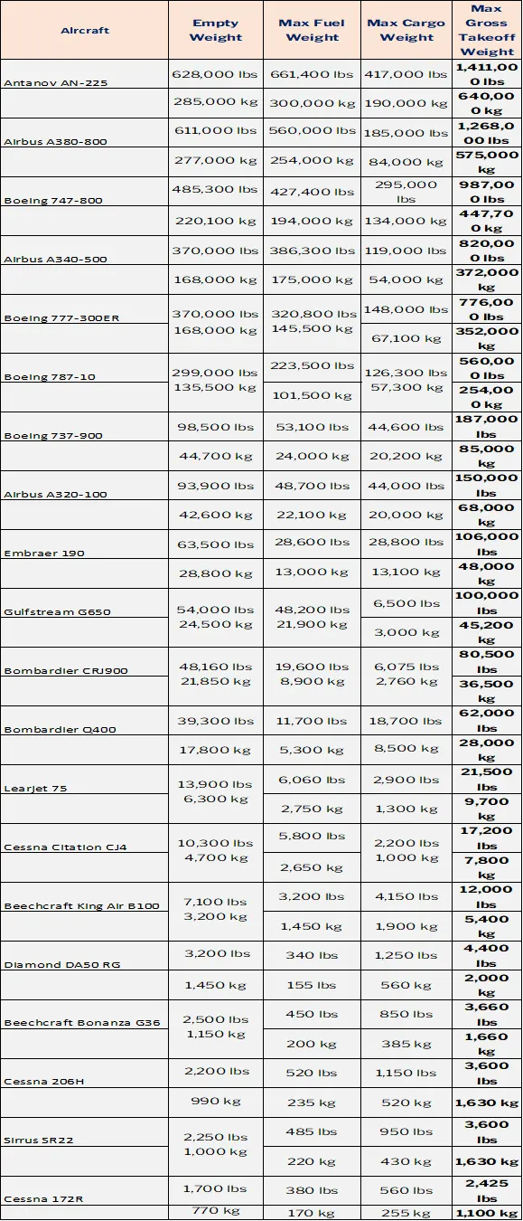
- Search and list out the total weight of various types of aircrafts.
- Is there any difference between ground speed and air speed?
- Why is it not recommended to use aircraft engine power to move it on the ground at Airport?
- How an aircraft is pushed to runway when its ready to take off?
- Learn about takeoff power, tire design, rolling resistance, tire pressure, brake forces when landing.
Part B:
- A. With necessary assumptions, calculate the force and power required to push / pull an aircraft by a towing vehicle.
- Develop the model for the calculated force and power using Simulink.
- A. Design an electric powertrain with type of motor, it’s power rating, and energy requirement to fulfill aircraft towing application in Simulink. Estimate the duty cycle range to control the aircraft speed from zero to highest. Make all required assumptions. Prepare a table of assumed parameters. Draw a block diagram of powertrain.
(Hint :DC7 Block)
- Also, Design the parameters in excel sheet.
Part A:
- List of the total weight of various types of aircrafts
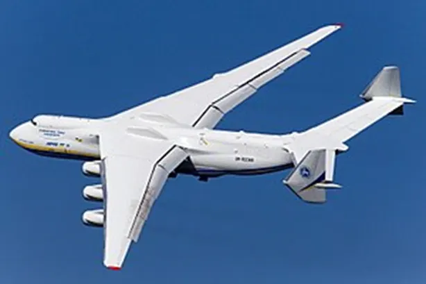
Antonov An-225
The Antonov An-225 Mriya was a strategic airlift cargo aircraft designed in the 1980s by the Antonov Design bereau in the Soviet Union. It was originally developed as an enlargement of the Antonov An-124 to transport Buran-class orbiters, and only one example was ever completed. After successfully fulfilling its military missions, the aircraft was mothabelled for eight years. It was then refurbished and reintroduced into commercial operation with Antov Airlines, carrying oversized payloads. While a second airframe with a slightly different configuration was partially built, construction was halted more than once due to a lack of funding and interest. This second aircraft was last brought up to 60–70% completion in 2009.
Airbus A380
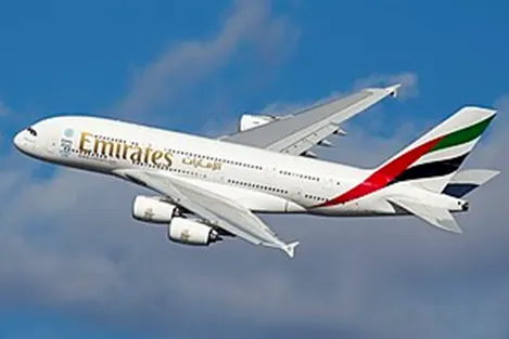
The Airbus A380 is a large wide-body airliner that was developed and produced by Airbus. It is the world's largest passenger airliner and only full-length double-deck jet airliner. Airbus studies started in 1988, and the project was announced in 1990 to challenge the dominance of the Boeing 747 in the long-haul market. The then-designated A3XX project was presented in 1994; Airbus launched the €9.5 billion ($10.7 billion) A380 programme on 19 December 2000. The first prototype was unveiled in Toulouse on 18 January 2005, with its first flight on 27 April 2005. It then obtained its type certification certificate from the European Aviation Safety Agency (EASA) and the US Federal Aviation Administration(FAA) on 12 December 2006. Due to difficulties with the electrical wiring, the initial production was delayed by two years and the development costs almost doubled.
Boeing 747
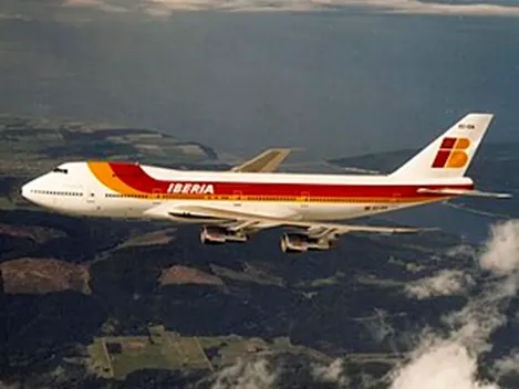
The Boeing 747 is a large, long-range wide body airliner designed and manufactured by Boeing commercial Airlines in the United States. After introducing the 707 in October 1958, Pan Am wanted a jet 2+1⁄2 times its size, to reduce its seat cost by 30% to democratize air travel. In 1965, Joe Sutterleft the 737 development program to design the 747, the first twin-aisle airliner. In April 1966, Pan Am ordered 25 Boeing 747-100 aircraft and in late 1966, pratt & Whitney agreed to develop its JT9D engine, a high by-pass turbofan. On September 30, 1968, the first 747 was rolled out of the custom-built Everrett Plant, the world's largest building by volume. The first flight took place on February 9, 1969, and the 747 was certified in December of that year. It entered service with Pan Am on January 22, 1970. The 747 was the first airplane dubbed "Jumbo Jet", the first wide-body airliner.
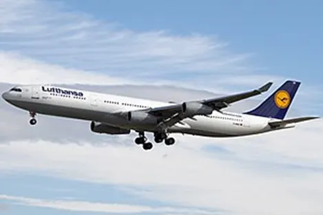
Airbus A340
The Airbus A340 is a long range, wide body passenger airliner that was developed and produced by Airbus. In the mid-1970s, Airbus conceived several derivatives of the A300, its first airliner, and developed the A340 quadjet in parallel with the A330 twinjet. In June 1987, Airbus launched both designs with their first orders and the A340-300 took its maiden flight on 25 October 1991. It was certified along with the A340-200 on 22 December 1992 and both versions entered service in March 1993 with launch customers Lufthansa and Air France. The larger A340-500/600 were launched on 8 December 1997; the A340-600 flew for the first time on 23 April 2001 and entered service on 1 August 2002.
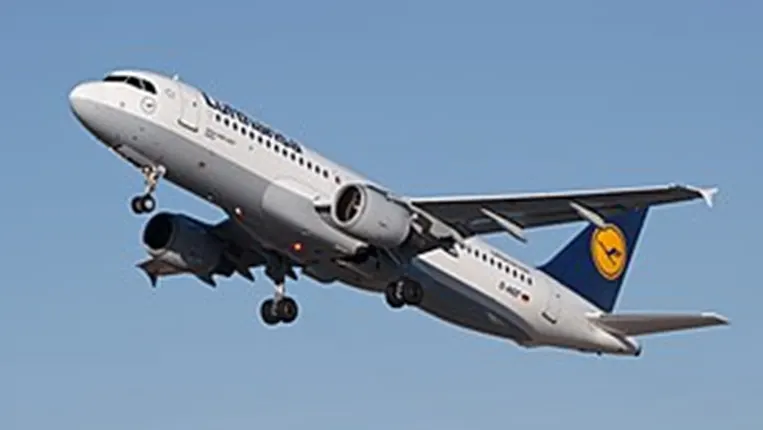
Airbus A320
The Airbus A320 family is a series of narrow body airlinersdeveloped and produced by Airbus. The A320 was launched in March 1984, first flew on 22 February 1987, and was introduced in April 1988 by Air France. The first member of the family was followed by the longer A321 (first delivered in January 1994), the shorter A319 (April 1996), and the even shorter A318 (July 2003). Final assembly takes place in Toulouse in France; Hamburgin Germany; Tianjinin China since 2009; and in Mobile, Alambain the United States since April 2016.
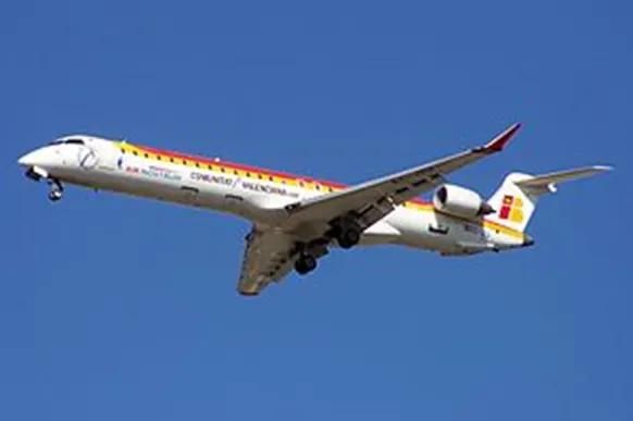
Bombardier
The Bombardier CRJ700, CRJ900, and CRJ1000 are a family of regional jet airliners that were designed and manufactured by Canadian transportation conglomerate Bombardier (formerly Canadair) between 1999 and 2020. Their design was derived from the smaller CRJ100 and 200 airliners, the other members of the Bombardier CRJ aircraft family. The CRJ program was acquired by Japanese corporation Mitsubishi heavy Industries in 2020, which ended production of the aircraft.
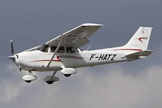
Cessna 172 Skyhawk
The Cessna 172 Skyhawk is an American four-seat, single-engine, high wing, fixed wing aircraftmade by the Cessna Aircraft company. First flown in 1955,more 172s have been built than any other aircraft. It was developed from the 1948 Cessna 170 but with tricycle landing gear rather than conventional landing gear. The Skyhawk name was originally used for a trim package, but was later applied to all standard-production 172 aircraft, while some upgraded versions were marketed as the Cutlass.
- Difference between ground speed and air speed
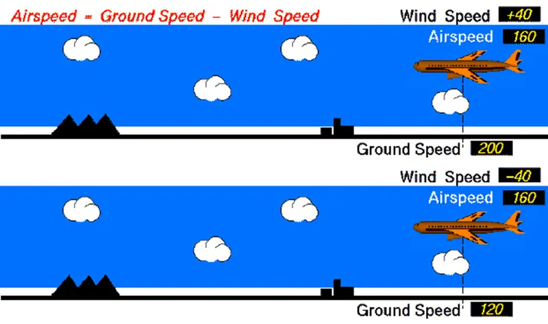
One of the most confusing concepts for young scientists is the relative velocity between objects. Aerodynamic forces are generated by an object moving through a fluid (liquid or gas). A fixed object in a static fluid does not generate aerodynamic forces. Hot air balloons "lift" because of buoyancy forces and some aircraft like the Harrier use thrust to "lift" the vehicle, but these are not examples of aerodynamic lift. To generate lift, an object must move through the air, or air must move past the object. Aerodynamic lift depends on the square of the velocty between the object and the air. Now things get confusing because not only can the object be moved through the air, but the air itself can move. To properly define the relative velocity, it is necessary to pick a fixed reference point and measure velocities relative to the fixed point. In this slide, the reference point is fixed to the ground, but it could just as easily be fixed to the aircraft itself. It is important to understand the relationships of wind speed to ground speed and airspeed.
Wind Speed
For a reference point picked on the ground, the air moves relative to the reference point at the wind speed. Notice that the wind speed is a vector quantity and has both a magnitude and a direction. Direction is important. A 20 mph wind from the west is different from a 20 mph wind from the east. The wind has components in all three primary directions (north-south, east-west, and up-down). In this figure, we are considering only velocities along the aircraft's flight path. A positive velocity is defined to be in the direction of the aircraft's motion. We are neglecting cross winds, which occur perpendicular to the flight path but parallel to the ground, and upwards and downdrafts, which occur perpendicular to the ground.
Ground Speed
For a reference point picked on the ground, the aircraft moves relative to the reference point at the ground speed. Ground speed is also a vector quantity so a comparison of the ground speed to the wind speed must be done according to rules for vector comparisons.
Airspeed
The important quantity in the generation of lift is the relative velocity between the object and the air, which is called the airspeed. Airspeed cannot be directly measured from a ground position, but must be computed from the ground speed and the wind speed. Airspeed is the vector difference between the ground speed and the wind speed.
Airspeed = Ground Speed - Wind Speed
On a perfectly still day, the airspeed is equal to the ground speed. But if the wind is blowing in the same direction that the aircraft is moving, the airspeed will be less than the ground speed.
Examples
Suppose we had an airplane that could take off on a windless day at 100 mph (liftoff airspeed is 100 mph). We are at an airport with an east-west runway that is 1 mile long. The wind is blowing 20 mph towards the west and the airplane takes off going east. The wind is blowing towards the aircraft which we call a headwind. Since we have defined a positive velocity to be in the direction of the aircraft's motion, a headwind is a negative velocity. While the plane is sitting still on the runway, it has a ground speed of 0 and an airspeed of 20 mph:
Airspeed = Ground Speed (0) - Wind Speed (-20) = 20 mph
The airplane starts its take off roll and has a constant acceleration a. From Newton's second law of motion, the ground speed V at any time t is:
V = a * t
and the distance d down the runway at any time is:
d = 1/2 * a * t^2
For a fixed length runway, this specifies the time to be used in the velocity equation. Let's assume that at 5000 feet down the runway, the velocity is 80 mph. Then the airspeed is given by
Airspeed = Ground Speed (80) - Wind Speed (-20) = 100 mph
and the airplane begins to fly. Now another pilot, with exactly the same airplane decides to take off to the west. The wind is now in the same direction as the motion and this is called a tailwind. The sign on the wind speed is now positive, not negative as with the headwind. The acceleration along the ground is the same, so at 5000 feet down the runway, the ground speed is again 80 mph. The airspeed is then given by:
Airspeed = Ground Speed (80) - Wind Speed (20) = 60 mph
This airplane doesn't have enough airspeed to fly. It runs off the end of the runway.
- Why is it not recommended to use aircraft engine power to move it on the ground at Airport
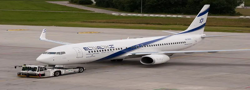
Airplanes get towed when the thrust of their engines creates a significant hazard to the immediate area surrounding them. Planes also get towed for maintenance purposes so pilots are not required to move the aircraft as airplane mechanics are trained in the use of the aircraft brakes while towing.
When aircraft go in for maintenance or are not required for flight by far the easiest way is to send a tow vehicle to the gate and have the maintenance team tow the aircraft to the hanger or parking areas. By doing this it allows time freedom for the airline, the airport ground controllers, and the maintenance team as pilots are not required to start the engines, here reasons some reasons for Why is it not recommended to use aircraft engine power to move it on the ground at Airport
- AIRCRAFT ENGINES CAN CREATE HAZARDOUS CONDITIONS
Aircraft towing equipment is typically used for the towing and pushback process to avoid some of the significant hazards posed by aircraft engines. When an aircraft's engine is activated, the thrust can create a high-speed wind that can easily cause damage to the airport terminal, surrounding ground vehicles, jetway, baggage and most importantly, ground personnel. Suppressing the use of engines is especially important when towing a large aircraft, as their more powerful thrust capabilities can become exceedingly dangerous. Engine thrust can easily send any loose items airborne, turn the tiniest grains of dust into hazardous projectiles and create debris that can cause damage to multi-million-dollar engines. Additionally, aircraft engines consume a great deal of fuel and generate extreme noise that can be harmful to ground personnel. Using a pushback tug for aircraft is simply a more economical and safer option than running the engines.
- AIRCRAFT TOWING IS EASIER FOR MAINTENANCE PURPOSES
Towing and pushback tugs for aircraft are also used to make general maintenance easier for ground personnel. When an aircraft needs to be moved to a hangar for maintenance purposes or is not required for flight, the easiest way is to send an aircraft tug to the tow-in gate for transport. Aircraft towing frees up time for the airline, maintenance team, airport ground controllers and pilots who don't need to waste time getting the engines started. It's also not cost-efficient to start aircraft engines just to reposition an aircraft for maintenance purposes. Typically, ground personnel are trained to only need the aircraft brake system when towing a large aircraft.
- PILOTS HAVE LIMITED VISIBILITY FROM THE FLIGHT DECK
Pilots do not have a clear view of the rear from the flight deck and thus rely on aircraft towing equipment for grownd pushback when needed. Once the aircraft is perfectly positioned and far from the terminal tow-in gate and other vehicles, the airport tug is disconnected and the aircraft can use its engines and steering to move to the runway for takeoff.
- TERMINAL TOW-IN GATES ARE CONFINED SPACES
Another common reason aircraft towing equipment is used in airports concerns aircraft safety from the taxiway to the tow-in gate. Aircraft towing from the taxiway occurs with significant time constraints, so pilots and ground personnel are under extreme pressure to navigate the aircraft quickly and efficiently. The tight confines of the terminal tow-in gate combined with the restricted view of the pilots generally always require a tow in order to arrive safely and on time. Even thoughpilots follow taxi centerlines, aircraft with very large wingspans are often faced with the challenge of having adequate clearance. If an airplane connects with another aircraft or hits a gate terminal, it can cause significant damage, huge expenses and contribute to lost time for extra maintenance repairs. Aircraft towing can prevent contact with other structures because ground personnel have much better visibility from the airplane tug. With the aid of ground personnel walking with the wings and tail, the airport tug driver can precisely position the aircraft to ensure it will not hit a structure, vehicle, person or another aircraft. In addition to this, the airplane tug driver is in constant communication with the pilots to ensure the aircraft will brake if an emergency occurs.
- PUSHBACK TUGS FOR AIRCRAFT ARE REQUIRED FOR GOING IN REVERSE
Typically, most aircraft cannot move in reverse without the help of aircraft towing equipment. Planes are not designed with a reverse option that pilots can use for backward movement, so pushback tugs for aircraft are the only option when moving aircraft into hangars or away from the terminal building. This is because aircraft are not outfitted with gears or transmission for propulsion – power for movement is derived solely from the engines through thrust. When aircraft tugs are used to tow planes, an airline can maximize safety and optimize efficiency with on-ground operations.
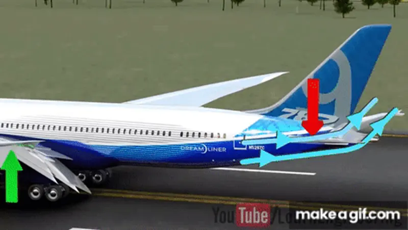
While most commercial airliners with jet engines have thrust-reversing capabilities, they can only be used as additional braking power during landing. In addition to the problems mentioned above associated with using aircraft engines, reverse thrust also has what is known as the lowest-speed-of-operation limit. If reverse thrust is used below the speed of 80kts, it's very likely the engines will become heavily damaged.
- How an aircraft is pushed to runway when its ready to take off
Airplanes have engines, and they can use them to move forward along the ground. So, they push themselves to the runway. It is true that most of the time, a small vehicle is needed to push the larger commercial airplanes backwards away from the terminal building, because even if a plane can reverse its thrust, it’s not always safe to hit the buildings with that reverse thrust. So, the little trucks push the bigger planes back away from the buildings, but after that, the planes can apply a small amount of engine power to roll forward just as all airplanes. Pushback is when an aircraft is pushed backwards away from the airport gate by vehicles called tugs or tractors. Closer to departure, an aircraft tug will park right in front of the nose wheel. The tug might be directly attached to the plane's nose gear with a tow bar, or could be a "wheel-lift" tug. These tugs cradle the nose gear, then lift it up before moving the plane. That gives the tug driver control over the plane's direction during pushback. New taxi technologies are appearing, like pilot-controlled tugs, and electric motors mounted to the plane's landing gear. Both promise to save fuel, and reduce airport noise.
5. Learn about takeoff power, tire design, rolling resistance, tire pressure, brake forces when landing.
Takeoff Power:
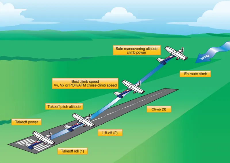
Although the takeoff and climb is one continuous maneuver, it will be divided into three separate steps for purposes of explanation: 1. takeoff roll, 2. lift-off, and 3. initial climb after becoming airborne. [Figure 5-1]
- Takeoff roll (ground roll) is the portion of the takeoff procedure during which the airplane is accelerated from a standstill to an airspeed that provides sufficient lift for it to become airborne.
- Lift-off is when the wings are lifting the weight of the airplane off the surface. In most airplanes, this is the result of the pilot rotating the nose up to increase the angle of attack (AOA).
- The initial climb begins when the airplane leaves the surface and a climb pitch attitude has been established. Normally, it is considered complete when the airplane has reached a safe maneuvering altitude or an en route climb has been established
The definition used by the Federal Aviation Administration for take‑off includes the ground run from zero ground speed to the point where the wheels leave the ground, plus the distance required to clear a 50-foot obstacle. The distance over the ground for all of the above is computed at maximum gross weight at sea level standard conditions. The “worst case” condition is often also calculated for a hot day at high altitude (100ºF in Denver).
We will concern ourselves only with the ground run portion of the take‑off run, knowing that we can find the distance to clear a 50-foot obstacle from our climb equations. That climb would be calculated for maximum angle of climb conditions.
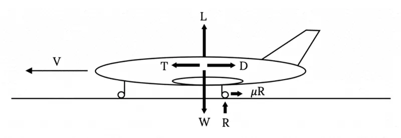
The first step in the calculation of the ground run needed for take‑off is an examination of the forces on the aircraft. In addition to the lift, drag, thrust and weight, we must now consider the ground friction and the “Resultant” force of the ground in supporting all or part of the weight of the aircraft. These are shown in the figure below. The coefficient of friction will depend on the ground surface and braking friction.
For Steady flight,
W=1/2*rho_infinity^2*V_infinity^2*SC_L
Power required Pr=Tr*V_infinity
Pr=W/(C_L/C_D)*V_infinity
Pr=sqrt((2W^3*C_d^2)/(rho_infinity*SC_L^3)
Tire design
The wheels and tires (tires) fitted to an aircraft are designed to support the full weight of that aircraft while on the ground, and transmit the static and dynamic loads generated during taxi, take-off and landing into the aircraft's shock absorption system (typically an oleo-pneumatic shock absorber or steel spring). The largest loads that the wheel/tire assembly sees occur during landing and are characterized by high speeds and large impact loads which deforms the tires, loading the wheel at the flanges. This tutorial focuses on the design and construction of the wheel and tire assembly as fitted to a typical aircraft.
Wheels
It is necessary to differentiate between the wheel and tire when discussing both components. The wheel is the name given to the cylindrical metallic structure that is connected to the landing gear axle through bearings, and is shaped to provide a seating surface for the tire. The tire is made primarily from rubber, and is the only part of the aircraft that comes in contact with the ground. Wheels are typically made from aluminum or magnesium alloy which is light and strong. The design of a modern aircraft wheel differs from the automotive wheels that you may be accustomed to. Automotive wheels are typically manufactured as a single assembly whereas aircraft wheels are constructed in two pieces and then fastened together after the tire is installed. This two-piece construction is necessary as an aircraft tire is designed to flex in order to absorb the very large impact loads without separating from the rim. The design of a flexible aircraft tire is not conducive to being stretched over a single piece wheel like that of a car.
Removable Flange Wheels
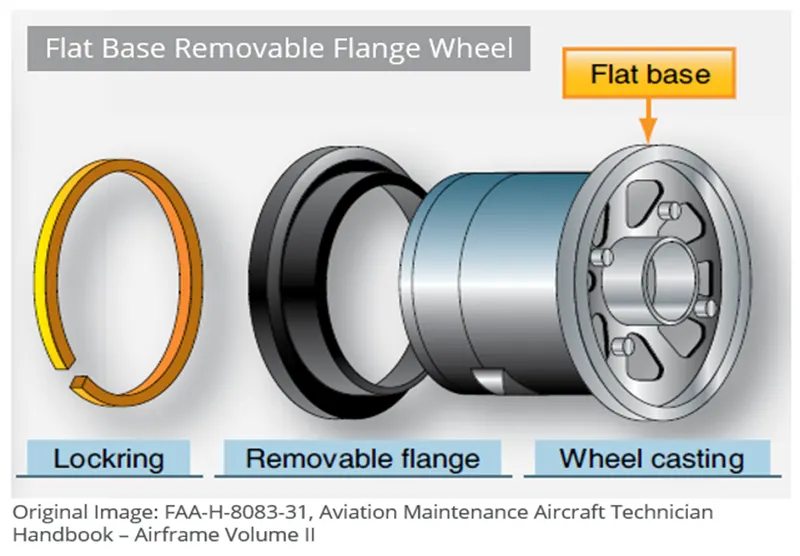
Early two-piece wheels were designed similar to an automotive tire, but with a removable flange that allowed the tire to be installed easily onto the wheel and then inflated to the desired pressure.
Modern Two-piece Wheel
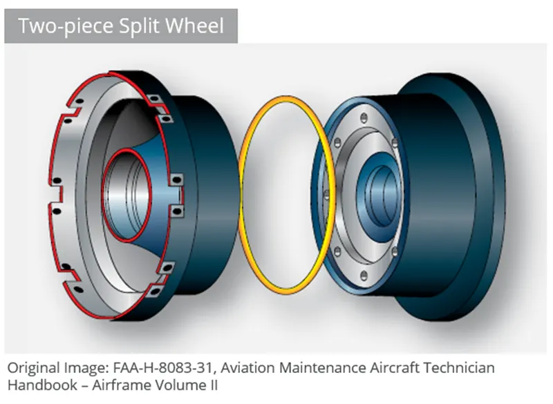
A more modern evolution of the flange removable wheel is the two-piece wheel, where the wheel is split into two near equal halves and bolted together with an o-ring in the center to form a tight rim seal. The two flanges form the bead seating region where the tire contacts the wheel. During touch-down the tire compresses rapidly, exerting a large tensile load in the flanges. The flanges are designed to withstand this loading and also to prevent the tire from slipping relative to the wheel under heavy braking.
Tires
The tire (tyre in British English) is the only part of the aircraft in contact with the ground, and a well-maintained set of tires is crucial to the safe operation of any aircraft. Tires cushion the impact on touch-down and transfer the energy of landing into the wheels. Aircraft tires differ substantially in their operating profile to automotive tires. Car tires are load bearing for a considerably longer time than an aircraft during a typical mission profile, albeit at relatively low speeds with slow accelerations. Aircraft tires on the other hand spend comparatively less time operating but must absorb very large impact loads and handle high speeds with large accelerations when in contact with the runway. Aircraft tires are designed to flex far more than automotive tires which assists in damping the large impact loads.
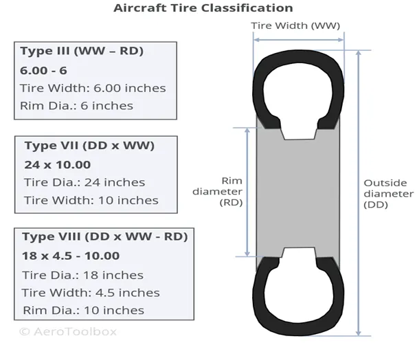
Tire Classification
Tires are typically classified according to their dimensions, strength (ply-rating) and configuration (tubed or tubeless). To ensure safe operation, the correct tire should always be fitted to a particular aircraft in accordance with the operating manual.
Dimensions and Sizing
Dimensional classification is usually made according to outer tire diameter, sectional width, and the diameter of the rim. A common classification system in use today is that of the United States Tire and Rim Association, where aircraft tires are classified as one of nine types. Today, three tire classifications cover almost all aircraft classes in use, from light aircraft up to modern jet airliners. These three classifications use a slightly different way to report the tire dimensions; this is described below.
Type III
Type III tires are common low-pressure general aviation tires predominantly used on light aircraft with reasonably low landing speeds. These tires are easily identified as they have a small rim diameter in comparison to their width. Type III tires are designated by a two-number system: the first number describes the nominal tire width and the second the diameter of the rim that the tire can be fitted to. The two numbers are separated by a dash.
Type VII
Type VII tires are high-pressure, high-performance tires fitted to jet aircraft. These tires are sized according to a two-number system that differs from the Type III classification described above. Here the first number designates the nominal overall diameter of the tire while the second number, which is separated from the first by a multiplication sign, gives the nominal section width.
Type VIII
Type VIII tires are designated by three numbers and incorporate the conventions of both the Part III and Part VII tires. The first number specifies the outside diameter, the second is the nominal tire width, and the third is the rim diameter. These tires are designed to operate at high-pressures and high speeds and are the most advanced tires in use on large jet aircraft today.
Rolling resistance
Sometimes called rolling friction or rolling drag, is the force resisting the motion when a body (such as a ball, tire, or wheel) rollson a surface. It is mainly caused bynon-elastic effects; that is, not all the energy needed for deformation (or movement) of the wheel, roadbed, etc., is recovered when the pressure is removed. Two forms of this are hysterisis losses, and permanent deformation of the object or the surface (e.g. soil). Note that the slippage between the wheel and the surface also results in energy dissipation. Although some researchers have included this term in rolling resistance, some suggest that this dissipation term should be treated separately from rolling resistance because it is due to the applied torque to the wheel and the resultant slip between the wheel and ground, which is called slip loss or slip resistance.In addition, only the so-called slip resistance involvesfriction, therefore the name "rolling friction" is to an extent a misnomer. Analogous with sliding friction, rolling resistance is often expressed as a coefficient times the normal force. This coefficient of rolling resistance is generally much smaller than the coefficient of sliding friction.
Any coasting wheeled vehicle will gradually slow down due to rolling resistance including that of the bearings, but a train car with steel wheels running on steel ralls will roll farther than a bus of the same mass with rubber tires running on tarmac/asphalt. Factors that contribute to rolling resistance are the (amount of) deformation of the wheels, the deformation of the roadbed surface, and movement below the surface. Additional contributing factors include wheel diameter, load on wheel, surface adhesion, sliding, and relative micro-sliding between the surfaces of contact. The losses due to hysteresis also depend strongly on the material properties of the wheel or tire and the surface. For example, a rubber tire will have higher rolling resistance on a paved road than a steel railroad wheel on a steel rail. Also, sandon the ground will give more rolling resistance than concrete. Sole rolling resistance factor is not dependent on speed.
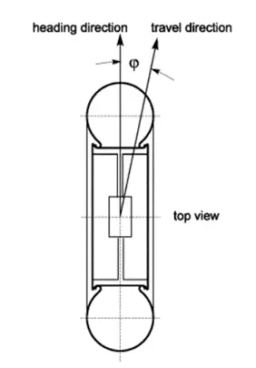
μR is defined by μR = F/G, where F is the force necessary to pull the axle of a tire horizontally in the direction of travel, and G is the vertical load on the tire which is assumed to roll on a flat horizontal surface. For a rolling tire the slip angle is defined as the angular distance between the heading direction and travel direction
The "rolling resistance coefficient" is defined by the following equation:
`Fr=Crr*m*g`
Fr=Crr*m*g
Were
Fr is the rolling resistance force
Crr is the dimensionless rolling resistance coefficient or coefficient of rolling friction (CRF), and
M Tolatal mass of the aircraft
g is Acceleration Gravity.
Crr is the force needed to push (or tow) a wheeled vehicle forward (at constant speed on a level surface, or zero grade, with zero air resistance) per unit force of weight. It is assumed that all wheels are the same and bear identical weight. Thus: Crr=0.01 means that it would only take 0.01 pounds to tow a vehicle weighing one pound. For a 1000-pound vehicle, it would take 1000 times more tow force, i.e. 10 pounds. One could say that Crr is in lb(tow-force)/lb(vehicle weight). Since this lb/lb is force divided by force, Crr is dimensionless. Multiply it by 100 and you get the percent (%) of the weight of the vehicle required to maintain slow steady speed. Crr is often multiplied by 1000 to get the parts per thousand, which is the same as kilograms (kg force) per metric ton (tone = 1000 kg ), which is the same as pounds of resistance per 1000 pounds of load or Newtons/kilo-Newton, etc. For the US railroads, lb/ton has been traditionally used; this is just 2000 Crr. Thus, they are all just measures of resistance per unit vehicle weight. While they are all "specific resistances", sometimes they are just called "resistance" although they are really a coefficient (ratio)or a multiple thereof. If using pounds or kilograms as force units, mass is equal to weight (in earth's gravity a kilogram a mass weighs a kilogram and exerts a kilogram of force) so one could claim that Crr is also the force per unit mass in such units. The SI system would use N/tonne (N/T, N/t), which is 1000g Crr and is force per unit mass, where g is the acceleration of gravity in SI units (meters per second square). The above shows resistance proportional to Crr but does not explicitly show any variation with speed, load, torque, surface roughness,diameter, tire inflation/wear, etc., because Crr itself varies with those factors. It might seem from the above definition of Crr that the rolling resistance is directly proportional to vehicle weight but itis not.
The coefficient of rolling resistance for a slow rigid wheel on a perfectly elastic surface, not adjusted for velocity, can be calculated by
Crr=sqrt(z/d)
Where
z is the sinkage depth
d is the diameter of the rigid wheel
The empirical formula for Crr for cast iron mine car wheels on steel rails is:

Where
D is the wheel diameter in inches
W is the load on the wheel in pounds-force
As an alternative to using Crr one can use Crr, which is a different rolling resistance coefficient or coefficient of rolling friction with dimension of length. It is defined by the following formula:
F=Nb/r
Where
F is the rolling resistance force,
r is the wheel radius,
b is the rolling resistance coefficient or coefficient of rolling friction with dimension of length, and
N s the normal force
The above equation, where resistance is inversely proportional to radius r seems to be based on the discredited "Coulomb's law" (Neither Coulomb's inverse square law nor Coulomb's law of friction. See dependence on diameter. Equating this equation with the force per therolling resistance coefficient, and solving for b, gives b = Crr. Therefore, if a source gives rolling resistance coefficient as a dimensionless coefficient, it can be converted to b, having units of length, by multiplying Crr by wheel radius r.
|
Crr |
b |
Description |
|
0.0003 to 0.0004 |
"Pure rolling resistance" Railroad steel wheel on steel rail |
|
|
0.0010 to 0.0015 |
0.1 mm |
Hardened steel ball bearings on steel |
|
0.0010 to 0.0024 |
0.5 mm |
Railroad steel wheel on steel rail. Passenger rail car about 0.0020 |
|
0.0019 to 0.0065 |
Mine car cast iron wheels on steel rail |
|
|
0.0022 to 0.0050 |
Production bicycle tires at 120 psi (8.3 bar) and 50 km/h (31 mph), measured on rollers |
|
|
0.0025 |
Special Michelin solar car/eco-marathon tires |
|
|
0.0050 |
Dirty tram rails (standard) with straights and curves |
|
|
0.0045 to 0.0080 |
Large truck (Semi) tires |
|
|
0.0055 |
Typical BMX bicycle tires used for solar cars |
|
|
0.0062 to 0.0150 |
Car tire measurements |
|
|
0.0100 to 0.0150 |
Ordinary car tires on concrete |
|
|
0.0385 to 0.0730 |
Stage coach (19th century) on dirt road. Soft snow on road for worst case. |
|
|
0.3000 |
Ordinary car tires on sand |
Tire Pressure
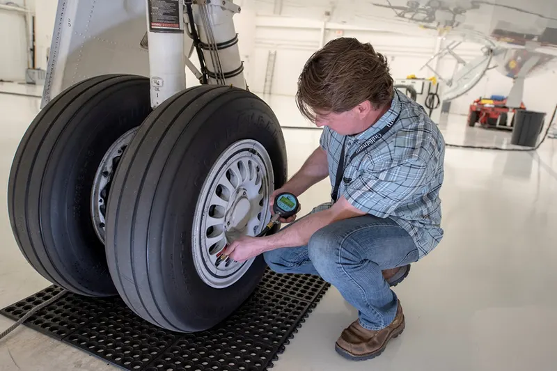
You might think that the guidance given by most manufacturers (aircraft and tire) are probably filtered through lawyers who say you need to check your tires every day and that pressure tolerances are very small. In some cases that might be true. You will have to comb through the guidance provided for your aircraft. I've done that for a Gulfstream G450 to give you an idea on the process of getting your own answers. What follows are procedures to service the tires, that is, to add nitrogen. But the procedures hold true for checking the tire pressures. "Low pressure" means something higher than what you need in the tire. We typically crank it up to between 300 and 400 psi. Dry nitrogen is important because you don't want any condensation inside the tire. But, more importantly, it has to be nitrogen and not air.
Air is 78% nitrogen, 21% oxygen, and 1% other stuff. The oxygen is what you have to worry about when using ambient air in tires. Air is more sensitive to temperature changes and the normal heating caused by taxi, takeoff, and landing will cause air to increase in pressure to a much greater extent than pure nitrogen. Air is also more flammable and more likely to "bleed" through rubber. Most aircraft wheels are of a "split rim" design. A conventional rim is made in one piece and the tire must be stretched over the rim. This is virtually impossible to do with many tires and the rim comes in sections so the tire can be installed on one section and then the second section is then secured to the first. What holds it all together? The rim itself has mating parts but the axle is also responsible for keeping both parts together. (That's why you should never remove a wheel from the axle without reducing the pressure first.) If any of this fails, the wheel will come apart. This is responsible for many deaths each year in the heavy trucking industry. Aircraft wheels have the same dangers. Whenever you check a tire's pressure with a pressure gauge, you have to release a small amount of air/nitrogen to get the reading and that invariably costs you a PSI or two. There are add-on tire stems that allow an electronic reader to do the same thing without losing any pressure.
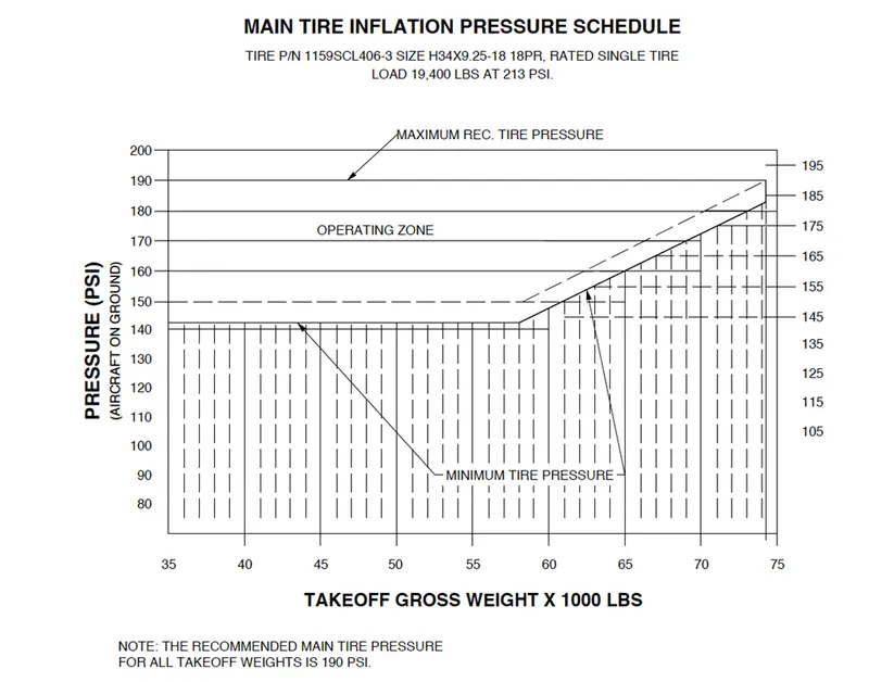
Does the pressure have to be at the tire's maximum?
This depends on your aircraft manufacturer. In the case of a Gulfstream G450, we have a chart that correlates our tire pressures with the maximum gross weight expected before the next servicing.
Brake forces when landing
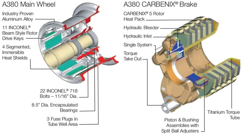
Disc brakes will squeeze the wheels, thereby slowing down the speed at which they spin. In turn, this reduces the speed of the airplane so that it can come to a complete stop on the runway. Brakes provide this critical stopping function during landings to enable airplanes to stop within the length of the runway. They also stop aircraft during rejected takeoff events, in which an attempted takeoff is canceled as the airplane is rolling down the runway before it lifts off from the ground due to engine failure, tire blowout, other system failure or direction from air traffic control. Aircraft brakes also prevent motion of the aircraft when it is parked, limit its speed during taxiing and can even help steer the aircraft on the ground by applying different levels of braking force to the left- and right-side brakes. Aircraft brakes work in conjunction with other brake mechanisms such as thrust reversers, air brakes and spoilers. Thrust reversers are surfaces that are deployed into the path of the jet blast from the engines to redirect propulsive thrust in a direction that opposes the motion of the aircraft. Air brakes and spoilers are flight control surfaces that create additional aerodynamic drag when deployed into the path of air flowing around the aircraft.
How aircraft brakes work
The most common type of brake used on aircraft is the disc brake. Disk brakes function by exploiting friction between rotating and stationary discs inside the brake. Upon receiving a command signal to brake — from the pilot depressing a foot pedal or from the autobrake system — actuators in the brake move a piston to squeeze the discs together, generating a frictional force that slows the rotation of the wheel. The friction between the discs generates heat as the aircraft’s kinetic energy is converted to heat energy. In this function, the brakes act as a heat sink, absorbing tremendous amounts of heat as the aircraft sheds kinetic energy. During RTO stops, the temperature of carbon disc brakes can exceed 1,800° C. The discs are mounted on a carrier assembly consisting of a torque tube, which resists and transmits brake torque to the landing gearstructure. Sandwiched together between the carrier assembly housing and a backing plate, the discs are arranged in an alternating pattern of rotors and stators. Notch and groove geometry around the circumference of each rotor fits into corresponding geometry in the wheel, keying the rotors to the wheel so that they rotate with it. The stators are keyed to the torque tube and are thus held stationary since the torque tube is connected to the axle and landing gear structure. Cylindrical spaces within the carrier assembly hold actator pistons. Braking occurs as piston force squeezes the discs together.
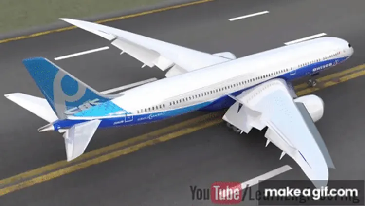
During each application of the brakes, disc material is worn away by frictional forces. A wear indicator in the form of a pin that protrudes out of the carrier assembly indicates the thickness of the stack of discs. Over hundreds of brake applications, material wears away and discs become thinner, requiring replacement following periodic maintenance intervals.
Brake design
The primary design considerations for aircraft brakes include the number of discs, the diameter of the discs and the material of the discs. A major design point around which aircraft brakes are designed is the worst-case scenario of rejected takeoff (RTO) at the maximum rolling speed V1, known as the decision speed. Above V1, a takeoff could not be safely aborted without serious risk of the airplane failing to stop before the end of the runway. In this situation, the brakes need to absorb more energy than any other scenario.
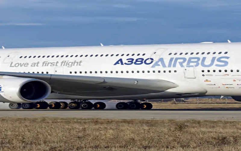
To illustrate how much energy this is, consider an Airbus A380 — the world’s biggest passenger airplane — performing an RTO at V1. The maximum take-off weight of an A380 is 575,000 kg (1,267,658 lb) and its maximum V1 is around 170 knots (about 195 mph or 87 m/s). A rough estimate for the maximum energy that the A380’s 16 brakes need to dissipate during RTO can be obtained by calculating the kinetic energy of the aircraft (neglecting the effects of thrust reversers, air brakes, tailwinds, headwinds and runway slope).
Brake force calculation
Lets Assume .
Landing weight = takeoff weight in case of aborted takeoff = 1500 lbf
Landing distance = 500 ft
Speed (assume aborted takeoff) = 60 kt (100 ft/sec)
We will use Newton’s second law to determine force due to deceleration:
Deceleration: from simple kinematics, acceleration = velocity^2 / distance
= (100 ft/s)^2 / 500 ft = 20 ft / s^2
Mass of aircraft = (weight) / g = 1500/32.2 = 46.58 lbf*s^2 / ft
Force = mass * acceleration (46.58 lbf*s^2/ft) * (20 ft / s^2) = 931.6 lbf
So in this example, the braking (deceleration) force is 931.6 lbf
6A To calculate the force and power required to push/pull an aircraft by a towing vehicle with necessary assumptions
In this study, we want to calculate the force and power required to push and pull an aircraft by towing vehicle so we take one of the towing vehicle model and airbus model on the website and consider the data for our calculation. The Douglas TBL-400 towbar less aircraft handling tractor is designed for pushback, inter-gate towing, and longer distance maintenance towing operations at higher speeds.
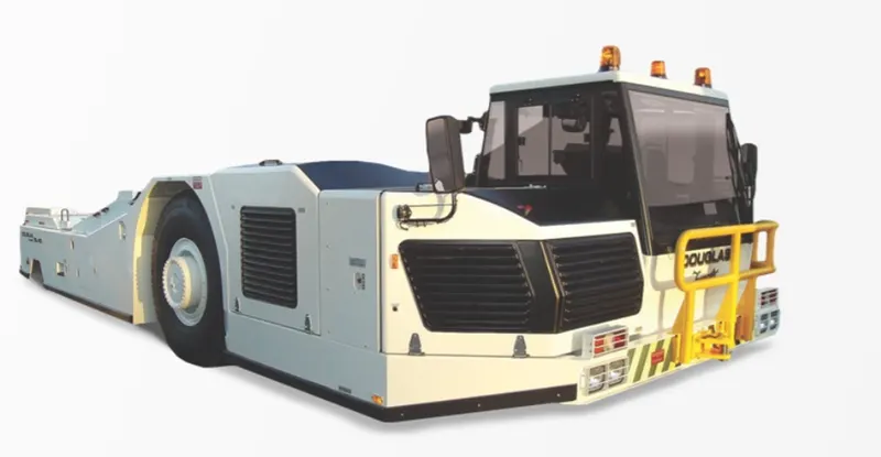
SPECIFICATIONS
DIMENSIONS
|
STANDARD WEIGHT |
65,918.2 lbs (29,900 kg) |
|
LENGTH (EXCLUDING COUPLER) |
376” (9,556 mm) |
|
WIDTH |
161” (4,100 mm) |
|
GROUND CLEARANCE |
9” (235 mm) |
|
TOP SPEED |
20 mph (32 kph) |
|
HITCH |
Single Position (Front Only) |
|
HEIGHT (WITH CAB LOWERED) |
84” (2140 mm) |
|
HEIGHT (WITH CAB RAISED) |
97” (2,460 mm) |
|
TURNING RADIUS (OVERBODY, UNLADEN) |
4WS: 318” (8,070 mm) |
Gross Weight = 29900Kg
Height = 2140 mm = 2.14m
Width = 4100 mm = 4.1m
Length (excluding coupler) = 9556 mm = 9.556m
Tire size = 22.5 radius = 571.5mm = 0.5715m
Maximum vehicle speed = 20kmph
Velocity of the vehicle = Speed*5/18
20*5/18 = 5.56 m/s
The coefficient of friction depends on the objects that are causing friction. The value is usually between 0 and 1 but can be greater than 1. A value of 0 means there is no friction at all between the objects. A value of 1 means the frictional force is equal to the normal force. It is a misconception that the coefficient of friction is limited to values between zero and one. A coefficient of friction that is more than one just means that the frictional force is stronger than the normal force.
Coefficient of rolling resistance (μrr) = 0.02 (Truck tyre in asphalt concrete road)
Lets Choose A318 Airbus
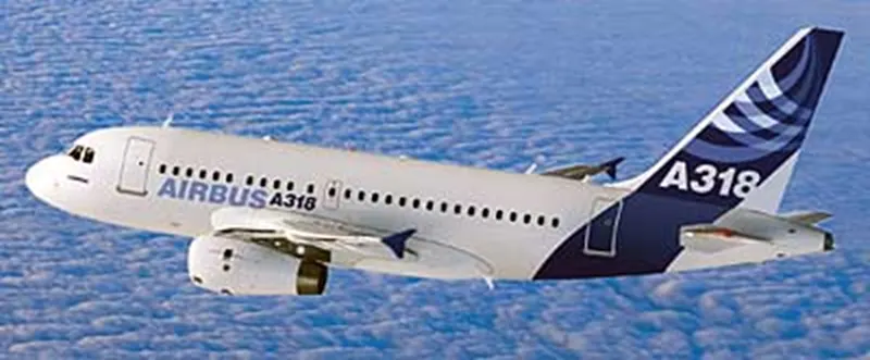

Gross Weight = 149900LB = 68400 Kg
Length = 31.4m
Height = 12.6m
Width = 34.1m
Air drag coefficient Cd = 0.0265
So, we know that Total tractive force
Fte=Frr+Fad
Therefore, Frr is total rolling resistance force
Frr = ‘mu’rr*m*g
‘mu’rr = 0.02,
m = Total mass (Airbus mass + Towing Vehicle weight) = 98300
g = Gravitational constant = 9.81
Frr = 0.02*98300*9.81
Frr = 19286 N
So, Rolling resistance force is Frr = 19286 N.
Air Drag force is
Fad = 0.5*’rho’*A*Cd*V^2
According to international standard atmosphere (ISA) value is ‘rho’ = 1.225 Kg/m^2
A = Area of the Airbus = Height*Width = 430m
Fad=0.5*1.225*430* 0.0265*5.5^2
Fad = 260 N
Therefore total Tractive Force is
Fte = Frr+Fad
Frr= 19286+260 = 19546 N
To find the power required by towing vehicle is
Ptow = Fte*V
Ptow =19546*5.6
Ptow = 108593w
Ptow = 108.593Kw
B. Develop the model for the calculated force and power using Simulink
From the above calculated force and power equations, we can develop the mode using Simulink.
% The force and power required to push / pull an aircraft by a towing vehicle.
r = 0.5715; %radius of the Tug vehicle tyre in meter
Tug_weight = 29900; %Kg
Airbus_weight = 68400; %Kg
Airbus_height = 12.6; % meters
Airbus_width= 34.1; % meters
Cd = 0.0265; % Air drag coefficient
Urr = 0.02; % Rolling resistance coefficient
g = 9.81; % Gravitational constant
rho = 1.225; % According to international Standard Atmosphere (ASI) value
Tug_Speed = 20; %kmph 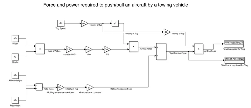
Model Explanation:
- Used Constant block for input values from workspace which is saved as .m file
- Gain block used for multiplication to get required equation and input values taken from workspace which is saved as .m file
- Product block used to multiply two or more models
- Addition block used to add two or more blocks
- Display block used to display force and power required for the Tug vehicle.
Here below shown input values of MATLAB script code, saved in .m file
% The force and power required to push / pull an aircraft by a towing vehicle.
Tug_weight = 29900; %Kg
Airbus_weight = 68400; %Kg
Airbus_height = 12.6; % meters
Airbus_width= 34.1; % meters
Cd = 0.0265; % Air drag coefficient
Urr = 0.02; % Rolling resistance coefficient
g = 9.81; % Gravitational constant
rho = 1.225; % According to international Standard Atmosphere (ASI) value
Tug_speed = 20; % Speed of the Tug
|
force and power required to push/pull an aircraft by a towing vehicle |
|
|
ROLLING RESISTANCE FORCE CALUCLATION |
|
|
Airbus Weight (KG) |
68400 |
|
Towing vehicle Wight (KG) |
29900 |
|
COEFFICIENT OF ROLLING RESISTANCE |
0.02 |
|
ROLLING RESISTANCE FORCE (N) |
19286.46 |
|
AIR DRAG FORCE CALUCLATION |
|
|
AIR DENSITY (kg/m^3) |
1.225 |
|
WIDTH (m) |
34.1 |
|
HEIGHT (m) |
12.6 |
|
FRONTAL AREA (m^2) |
429.66 |
|
DRAG COEFICIENT |
0.0265 |
|
SPEED (KMPH) |
20 |
|
AIR DRAG FORCE (N) |
260.4457358 |
|
Total Force |
19546.90574 |
|
TOTAL POWER REQUIRED BY TOWING VEHICLE IS |
108.5939208 |
7A. Design an electric powertrain with type of motor, it’s power rating, and energy requirement to fulfill aircraft towing application in Simulink. Estimate the duty cycle range to control the aircraft speed from zero to highest. Make all required assumptions. Prepare a table of assumed parameters. Draw a block diagram of powertrain.
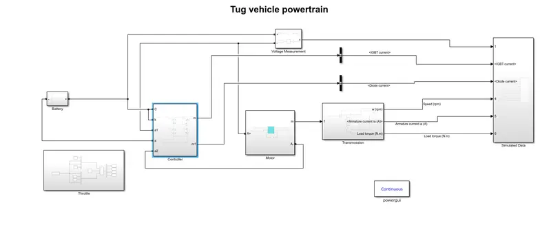
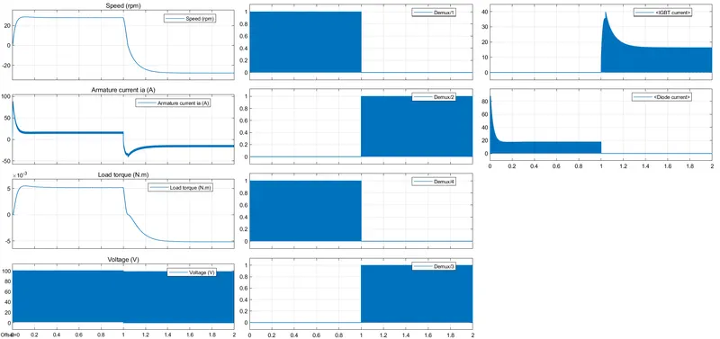
Here im used four quadrant chopper As controller for Motor speed variariation with 70% duty cycle.
Assumed parametrs
| Assumed parameters | |
| Battery Voltage | 100 |
| Motor sspecificarions | |
| Power rating (Hp) | 125 |
| Voltage rating( V) | 500 |
| Speed | 1750 |
| Field Voltage | 300 |
| Amature current | 100 |
| Armature resistance | 0.5 |
| Duty cycle % | 70 |
| Supply voltage V | 70 |
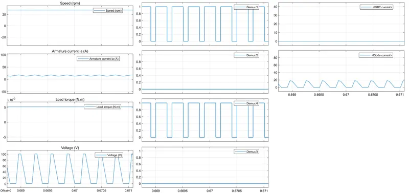
Now we got a plot