Project-1: Powertrain for aircraft in runways
Aim: Powertrain for aircraft in runways
Part A:
- Search and list out the total weight of various types of aircrafts.
- Is there any difference between ground speed and air speed?
- Why is it not recommended to use aircraft engine power to move it on the ground at Airport?
- How an aircraft is pushed to runway when its ready to take off?
- Learn about take-off power, tyre design, rolling resistance, tyre pressure, brake forces when landing.
- Search and list out the total weight of various types of aircrafts.
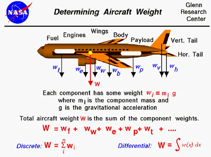
The weight of the aircraft is needed to be calculated by the pilot for every flight to ensure the aircraft remains within weight limitations set by the manufacturer. These limitations are to ensure the aircraft is able to perform and recover from all flight manoeuvres and withstand structural loading.
An aircraft’s empty weight, fuel, passengers & cargo must not weigh more than the aircraft’s Maximum Gross Takeoff Weight.
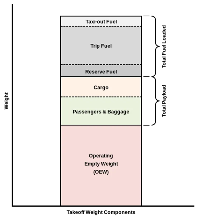
Aircraft Empty Weight (AEW):
This is sometimes referred to as OEW – Operating Empty Weight and it is the weight of the aircraft with all its equipment on board but no fuel, no passengers, or no cargo.
Think of this like the aircraft has just come out of the factory and is sitting waiting to be fuelled up for delivery to the customer.
Aircraft Maximum Gross Takeoff Weight (MGTW):
This is the maximum permissible weight the aircraft can weigh as it lifts off the ground at takeoff. This includes the aircraft’s empty weight, the fuel, the crew, the passengers, and all the cargo.
This weight limit is set by the manufacturer and is gospel. Many aircraft accidents have been caused by an aircraft being overweight and the pilot/s have not had enough power or manoeuvrability to prevent the accident.
Aircraft Useful Load:
This is the weight that a pilot can place in the aircraft. Take the MGTW figure and subtract the AEW and this is the total useful load that can be placed into the aircraft. This is the fuel, crew, passengers, and cargo. The bigger the load, the more useful the aircraft can be to its customers!
Typical Airplane Weights
Below is a table of some of the most common aircraft flying around our skies today:
|
Aircraft |
Empty Weight |
Max Fuel Weight |
Max Cargo Weight |
Max Gross Takeoff Weight |
|
628,000 lbs |
661,400 lbs |
417,000 lbs |
1,411,000 lbs |
|
|
611,000 lbs |
560,000 lbs |
185,000 lbs |
1,268,000 lbs |
|
|
485,300 lbs |
427,400 lbs |
295,000 lbs |
987,000 lbs |
|
|
370,000 lbs |
386,300 lbs |
119,000 lbs |
820,000 lbs |
|
|
370,000 lbs 168,000 kg |
320,800 lbs 145,500 kg |
148,000 lbs |
776,000 lbs |
|
|
299,000 lbs 135,500 kg |
223,500 lbs |
126,300 lbs 57,300 kg |
560,000 lbs |
|
|
98,500 lbs |
53,100 lbs |
44,600 lbs |
187,000 lbs |
|
|
93,900 lbs |
48,700 lbs |
44,000 lbs |
150,000 lbs |
|
|
63,500 lbs |
28,600 lbs |
28,800 lbs |
106,000 lbs |
|
|
54,000 lbs 24,500 kg |
48,200 lbs 21,900 kg |
6,500 lbs |
100,000 lbs |
|
|
48,160 lbs 21,850 kg |
19,600 lbs 8,900 kg |
6,075 lbs 2,760 kg |
80,500 lbs |
|
|
39,300 lbs |
11,700 lbs |
18,700 lbs |
62,000 lbs |
|
|
13,900 lbs 6,300 kg |
6,060 lbs |
2,900 lbs |
21,500 lbs |
|
|
10,300 lbs 4,700 kg |
5,800 lbs |
2,200 lbs 1,000 kg |
17,200 lbs |
|
|
7,100 lbs 3,200 kg |
3,200 lbs |
4,150 lbs |
12,000 lbs |
|
|
3,200 lbs |
340 lbs |
1,250 lbs |
4,400 lbs |
|
|
2,500 lbs 1,150 kg |
450 lbs |
850 lbs |
3,660 lbs |
|
|
2,200 lbs |
520 lbs |
1,150 lbs |
3,600 lbs |
|
|
2,250 lbs 1,000 kg |
485 lbs |
950 lbs |
3,600 lbs |
|
|
1,700 lbs |
380 lbs |
560 lbs |
2,425 lbs |
Highlight:
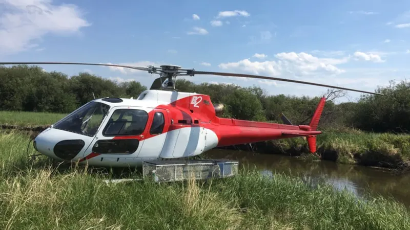
Eurocopter AS350 Astar B2 Helicopter
AS350 Astar B2 Helicopter Specs:
Aircraft Empty Weight: 3000 lbs
Aircraft Maximum Gross Weight: 4961 lbs
Aircraft Maximum Fuel Weight: 1000 lbs
Aircraft Useful Load: 1961 lbs
Reference:
Article:
https://pilotteacher.com/how-much-do-airplanes-weigh-with-20-examples/
Images Source: Google
_________________________________________________________________________________________________________________________________________________________________________________________________________
- Is there any difference between ground speed and air speed?
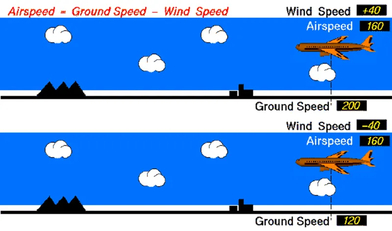
Generally speaking, there are two different types of speed when talking about airplanes: ground speed and airspeed.
Ground speed is the airplane’s speed relative to the surface of the Earth, airspeed – at least true airspeed – is its speed relative to the air it is flying in.
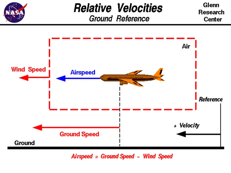
One of the most confusing concepts for young scientists is the relative velocity between objects. Aerodynamic forces are generated by an object moving through a fluid (liquid or gas). A fixed object in a static fluid does not generate aerodynamic forces. Hot air balloons "lift" because of buoyancy forces and some aircraft like the Harrier use thrust to "lift" the vehicle, but these are not examples of aerodynamic lift.
Wind Speed:
For a reference point picked on the ground, the air moves relative to the reference point at the wind speed. Notice that the wind speed is a vector quantity and has both a magnitude and a direction. Direction is important. A 20 mph wind from the west is different from a 20-mph wind from the east. The wind has components in all three primary directions (north-south, east-west, and up-down). In this figure, we are considering only velocities along the aircraft's flight path. A positive velocity is defined to be in the direction of the aircraft's motion. We are neglecting cross winds, which occur perpendicular to the flight path but parallel to the ground, and updraft and downdraft, which occur perpendicular to the ground.
- Ground Speed
- Airspeed
Ground Speed:
For a reference point picked on the ground, the aircraft moves relative to the reference point at the ground speed. Ground speed is also vector quantity so a comparison of the ground speed to the wind speed must be done according to rules for vector comparison.
Airspeed:
The important quantity in the generation of lift is the relative velocity between the object and the air, which is called the airspeed. Airspeed cannot be directly measured from a ground position, but must be computed from the ground speed and the wind speed. Airspeed is the vector difference between the ground speed and the wind speed.
Airspeed = Ground Speed - Wind Speed
On a perfectly still day, the airspeed is equal to the ground speed. But if the wind is blowing in the same direction that the aircraft is moving, the airspeed will be less than the ground speed.
Examples:
Suppose we had an airplane that could take off on a windless day at 100 mph (liftoff airspeed is 100 mph). We are at an airport with an east-west runway that is 1 mile long. The wind is blowing 20 mph towards the west and the airplane takes off going east. The wind is blowing towards the aircraft which we call a headwind. Since we have defined a positive velocity to be in the direction of the aircraft's motion, a headwind is a negative velocity. While the plane is sitting still on the runway, it has a ground speed of 0 and an airspeed of 20 mph:
Airspeed = Ground Speed (0) - Wind Speed (-20) = 20 mph
The airplane starts its take off roll and has a constant acceleration a. From Newton's second law of motion, the ground speed V at any time t is:
V = a * t
and the distance d down the runway at any time is:
d = 1/2 * a * t^2
For a fixed length runway, this specifies the time to be used in the velocity equation. Let's assume that at 5000 feet down the runway, the velocity is 80 mph. Then the airspeed is given by
Airspeed = Ground Speed (80) - Wind Speed (-20) = 100 mph
and the airplane begins to fly. Now another pilot, with exactly the same airplane decides to take off to the west. The wind is now in the same direction as the motion and this is called a tailwind. The sign on the wind speed is now positive, not negative as with the headwind. The acceleration along the ground is the same, so at 5000 feet down the runway, the ground speed is again 80 mph. The airspeed is then given by:
Airspeed = Ground Speed (80) - Wind Speed (20) = 60 mph
This airplane doesn't have enough airspeed to fly. It runs off the end of the runway!
Reference:
NASA:
https://www.grc.nasa.gov/www/k-12/airplane/Animation/airrel/anrelw.html
____________________________________________________________________________________________________________________
- Why is it not recommended to use aircraft engine power to move it on the ground at Airport?
The risks which may arise from engine ground running relate to the potential for loss of control of the aircraft by those persons occupying the pilot seats in the flight deck. Unwanted consequences from such static running are mainly related to those arising from the unintended movement of the aircraft during engine running - effectively a loss of control - especially during high power engine running. Damage can occur to the aircraft itself, other aircraft nearby or to airside structures. In addition, there is a risk of injury to ground support personnel who may be in relatively close proximity to the aircraft.
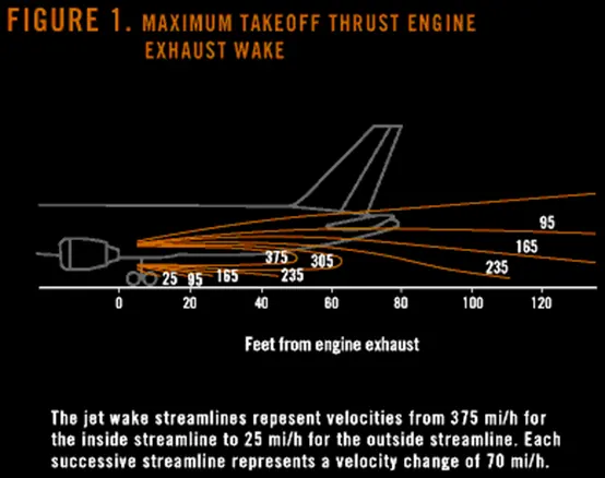
When modern jet engines are operated at rated thrust levels, the exhaust wake can exceed 375 mi/h (325 or 603 km/h) immediately aft of the engine exhaust nozzle. This exhaust flow field extends aft in a rapidly expanding cone, with portions of the flow field contacting and extending aft along the pavement surface (fig. 1). Exhaust velocity components are attenuated with increasing distance from the engine exhaust nozzle. However, an airflow of 300 mi/h (260 or 483 km/h) can still be present at the empennage, and significant people and equipment hazards will persist hundreds of feet beyond this area. At full power, the exhaust wake speed can typically be 150 mi/h (130 or 240 km/h) at 200 ft (61 m) beyond the airplane and 50 to 100 mi/h (43 to 88 or 80 to 161 km/h) well beyond this point.
The extensive noise arises from the engine power also dangerous for humans and other living things around the vicinity.
Hence for the above reasons it is not recommended to use engine power to move on the ground.
Reference:
Boeing:
https://www.boeing.com/commercial/aeromagazine/aero_06/textonly/s02txt.html
_________________________________________________________________________________________________________________________________________________________________________________________________________
- How an aircraft is pushed to runway when its ready to take off?
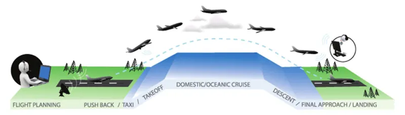
An aircraft engine has multiple functions. It is used for generating electricity to power the various systems in an aircraft. It also draws in air that’s needed inside the cabin. If the engines are switched off then the pilot has to turn on the APU or Auxiliary Power Unit — a generator running on the same jet fuel, inside the tail section of the plane. When an aircraft is parked at the gate, it draws its power from the ground power units. It also takes at least 3 - 5 minutes to power up the engines. That is a lot of time in an over crowded airport like Mumbai — which has only one functional runway. The waiting time for clearance is uncertain.
Aircraft Towing:
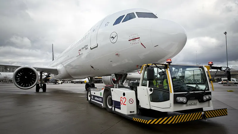
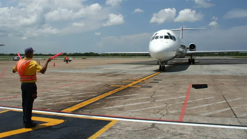
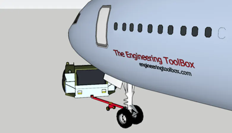
The forward movement of an aircraft, usually with engines off, using the power of a specialised ground vehicle attached to or supporting the nose landing gear. It may occur for the movement of both in service and out of service aircraft. This will affect the promulgation of procedures and the required qualification for those occupying the flight crew seats on the aircraft during the manoeuvre. As part of out of service repositioning of aircraft supervised by maintenance personnel, it may follow the pushback from a nose-in gate of an empty aircraft with engines off.
Aircraft Taxiing:
There are different ways that airplanes can be taxied. Taxiing is most commonly performed using an airplane’s own propulsion system. For propulsion, most airplanes have either jet engines or propellers. Engaging the propulsion system allows airplanes to move while on the runway.
Some airplanes also have thrust reversers. Thrust reversers live up to their namesake by changing the direction of an airplane’s thrust. In jet-engine airplanes, thrust reversers can assist with taxiing. It essentially allows airplanes to back up while on the runway.
Reference:
https://www.aircraftsystemstech.com/2018/12/towing-of-aircraft.html
https://monroeaerospace.com/blog/airplane-taxiing-an-introduction-to-taxiing-and-how-it-works/
____________________________________________________________________________________________________________________
- Learn about take-off power, tyre design, rolling resistance, tyre pressure, brake forces when landing.
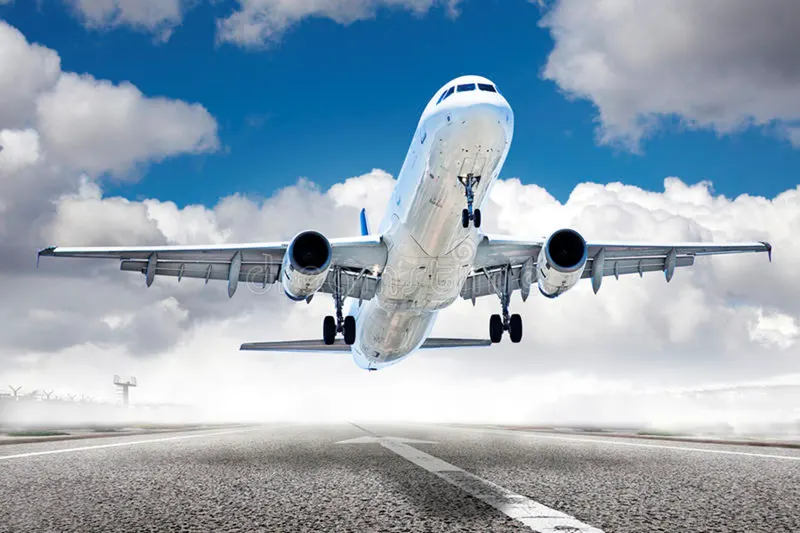
Takeoff is the phase of flight in which an aircraft leaves the ground and becomes airborne. For aircraft that take off horizontally, this usually involves starting with a transition and moving along the ground on a runway. For light weight aircraft, usually full power is used during takeoff. Large transport category (airliner) aircraft may use a reduced power for takeoff, where less than full power is applied in order to prolong engine life, reduce maintenance costs and reduce noise emissions. In some cases, the power used can then be increased to increase the performance. Before takeoff, the engines, particularly piston engines are routinely run up at high power to check for engine-related problems.
- Tire Design
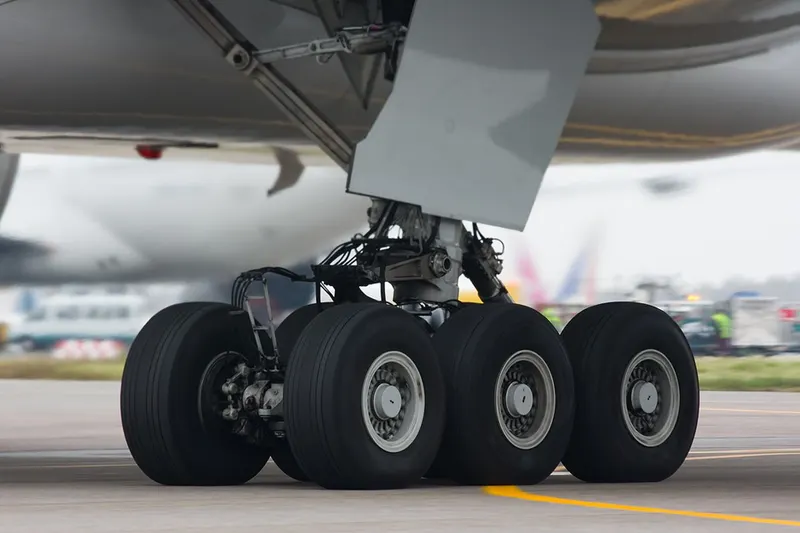
Designing aircraft tires is a very intense undertaking. Once an aircraft manufacturer goes to the tire manufacturer with the size and weight requirements, the tire manufacturer begins the process of designing a tire that meets the needs of the aircraft manufacturer as well as all regulatory requirements — including foreign regulations in many cases.
Engineers are challenged with designing tires with cool running, heat-resistant materials while simultaneously exceeding tire service requirements. Tire prototypes are put through rigorous tests that simulate cycles of landings, take-offs, and taxi operations. It is only after the tires pass all mandatory tests and meet the requirements of the aircraft manufacturer and airworthiness authorities that the tires are put into production.
Two types of tires are used in aircraft applications — bias-ply tires and radial tires. Although both types of tires share some similarities in design, there are differences that need to be noted.
Bias Ply Tires:
The specialty tire market has typically been divided into two segments—bias ply and radial. The term “bias ply” refers to the internal construction of the tire. In a bias ply tire, the cords (plies) run at a 45-degree angle from bead to bead. This diagonal pattern is criss-crossed with each layer of ply cord, and creates a very rigid structure. In the vintage car market, bias ply tires feature a narrow tread profile, with a sharp shoulder that usually has a piecrust look. The narrow tread pattern, and the fact that most bias ply tires mount to narrow wheels makes for a sidewall bulge that is easily identifiable and adds to the look of vintage cars.
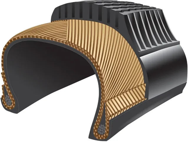
Cutaway view of a typical bias ply tire
Radial Tires:
Radial tires are a popular upgrade for collector enthusiasts who plan to get out and drive their old car. The more modern construction offers great improvements, including ride quality, wet weather traction and tread life, so it is a more practical option for most folks. The advantages are created by the tire’s construction, which consists of ply cords that run 90 degrees in relation to the bead. This radial orientation of the cords allows for a more flexible design, which conforms to the road surface, and allows the tires to skim across the ruts and breaks in the surface. This makes for a pleasant ride quality, even on rough roads, which would cause the wandering sensation with bias ply tires.
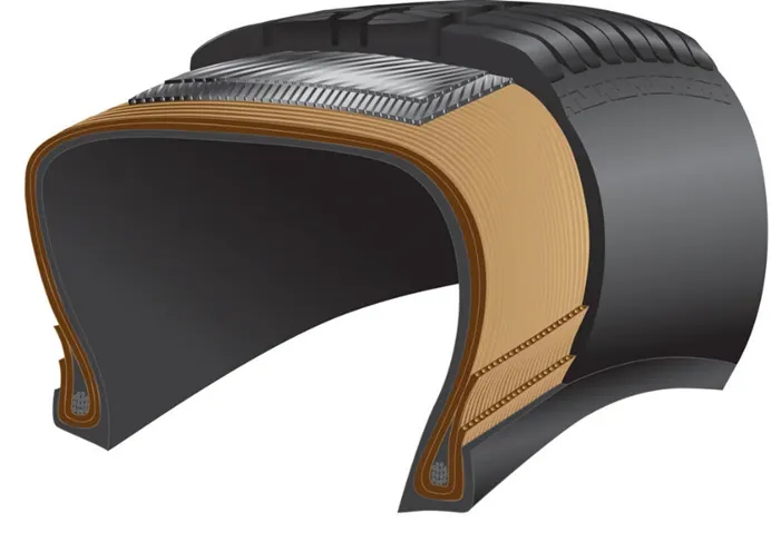
Cutaway view of a typical radial tire
Breakers: Breakers are reinforcing plies of rubber-coated fabric placed under the buff line cushion to protect casing plies and strengthen and stabilize the tread area. They are considered an integral part of the casing construction.
Tread: The tread is made of rubber mixed with other additives to obtain the desired level of toughness, durability, and resistance to wear. The tread pattern is designed to aircraft operational requirements, with the ribbed tread design used widely due to its good traction under varying runway conditions.
Sidewalls: The sidewall is a protective layer of rubber that covers the outer casing ply. It extends from the tread edge to the bead area.
Casing Plies: Alternate layers of rubber-coated fabric (running at opposite angles to one another) provide the strength of the tire
Chafers: A protective layer of rubber and/or fabric located between the casing plies and wheel to minimize chafing.
Ply Turnups: The casing plies are anchored by wrapping them around the wire beads, thus forming the ply turnups.
Flippers: Layers of rubberized fabric that help anchor the bead wires to the casing and improve the durability of the tire.
Wire Beads: Hoops of high tensile strength steel wire that anchor the casing plies and provide a firm mounting surface on the wheel. The outer edge of the bead that fits against the wheel flange is called the bead heel. The inner bead edge is called the bead toe.
Apex Strip: A wedge of rubber affixed to the top of the bead bundle.
Bead toe: It is the inner edge of the bead.
Bead heel: It is the outer edge of the heel.
Inner Liner: In tubeless tires, the liner is a layer of low permeability rubber that acts as a built-in tube and restricts gas from diffusing into the casing plies. In tube-type tires, a thinner liner is used to prevent tube chafing against the inside ply.
Caroass Plies: Layers of rubber-coated fabric piles which have the cords running from bead to bead. These provide the tire with strength in the sidewall area.
Tread Reinforcing Ply: One or more layers of fabric that strengthens and stabilizes the tread area for high-speed operation. It also serves as a reference for the buffing process when tires are retreaded.
Buff Line Cushion: The buff line cushion is made of rubber compound to enhance the adhesion between the tread reinforcing ply and the breakers or casing plies. It is of sufficient thickness to allow for the removal of the old tread when the tire is retreaded.
Tubeless tyres are more advantageous over tube-type. There is no longer the use of tube-type tyre in recent aviation.
Aircraft tyres must have an approved speed and load rating and have sufficient clearance when retracted through landing gear to allow for tyre growth. Tyre growth is the increase in the size of the tyre due to centrifugal forces at high speed.
Retreading – Retreading is methods of restoring a worn tyre by renewing the tread area or by renewing the tread area plus one or both sidewalls. Repairs are included in the tyre retreading process.
Load Rating – Load rating is the maximum permissible load at a specified inflation pressure.
Ply Rating – Ply Rating is used to identify the maximum recommended load rating and inflation pressure for a specified tyre. It is an index of tyre strength.
Speed Rating – The speed rating is the maximum takeoff speed to which the tyre has been tested.
Skid Depth – Skid depth is the distance between the tread surface and the deepest groove as measured in the mould.
Today’s tyres are conductive. Aircraft tyre are manufactured with tread rubber with conducting compounds to permit earthing of static charges. In early days when tyres were not sufficiently conductive, aircraft used to have a conductive strip hanging down from the axle of the landing gear. Upon landing, this strip would be the first part of the aircraft to touch the earth. This discharges any static electricity accumulated on the outer surfaces of the aircraft.
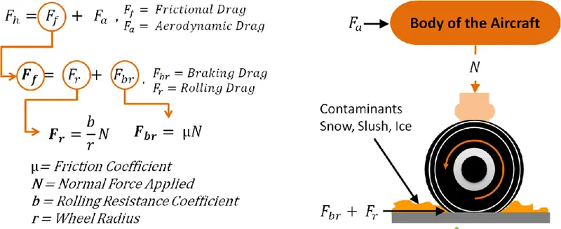
- Rolling Resistance:
When a tire moves over a surface covered with dry snow, it will deform the snow. The work needed for this deformation results in forces acting on the tire opposite to the direction of
motion. In general, the resistance of dry snow results from two forces
- compression resistance Dc
- vertical displacement resistance Dd
It is a method for predicting the rolling resistance of aircraft tires rolling in dry snow. Knowledge about the rolling resistance on a snow-covered surface is required when complying with aircraft certification and operational rules, which account for runway surface conditions. In addition to the rules, the Joint Aviation Authorities (JAA) have issued Advisory Material Joint AMJ 25X1591, a document providing information, guidelines, and recommendations for calculating the rolling resistance of aircraft tires in dry snow. The analytical method presented in AMJ 25X1591 gives unsatisfactory results when compared to experimental data. In this paper a new method is presented for predicting the rolling resistance due to snow. This new method and the AMJ method are validated by comparing the results of both methods for single tires and full-scale aircraft with available experiments. In general, a much better agreement with experimental data is found for the new method than for the AMJ method.
All these component were mounted in a heavy frame to form a unit which, in turn, to bolted to the bed of the truck.
- Tyre Pressure:
Of all the things that operators can do to improve the life of the aviation tire, maintaining good pressure maintenance is right at the top of every list. This article briefly explains why pressure maintenance is so important. For more information check out our useful guide!
No other tire has to deal with such high load and extreme speed as an airplane tire. So they need a bit more care than the tires on your car or motorcycle.
Think of the role of the tire as holding the air at a pressure that is able to support the load of the airplane. (Nitrogen is normally used in commercial operations instead of air.)
Like all things aviation, the tire is one part of an assembly which can only work as intended when the parts are used as defined by the airframe and component manufacturers.
Under-inflating the tire or allowing the tire to operate when it is under-inflated will prevent the parts working together as intended.
And it will be the tire that will take the strain. It will deflect more and it will wear more. Harsh operating environments will only make it worse.
Some of the wear will be visible – on the tread and some of the wear will be invisible – inside the structure of the aviation tire.
Visible Wear
Under-inflation will increase the footprint of the aviation tire as it rolls on the ground and will increase the build-up of heat. Heat is no friend to tires on airplanes and the tread will wear out more quickly than it should.
On multi-tire landing gear the under-inflated tire will force the other, maybe correctly inflated tires, to take a little bit more of the strain. This will wear those other tires a little more.
Invisible Wear
As extra heat caused by under-inflation builds up in the airplane tire the internal components of the tire might start to separate from each other. A catastrophic failure might result. Component separation in the casing of the tyre will prevent retreading and will increase operating costs. All for a bit of pressure maintenance!
24 Hour Pressure Checks
A carefully thought out pressure maintenance routine will increase the life of the tyre and will reduce the number of wheel changes required.
As all tires can allow a small pressure decrease during normal operations (due to the intense nature of their service life) airplane operators should check tire pressure every 24 hours.
Because putting the right pressure in the tires will always take pressure off the airplane operation.
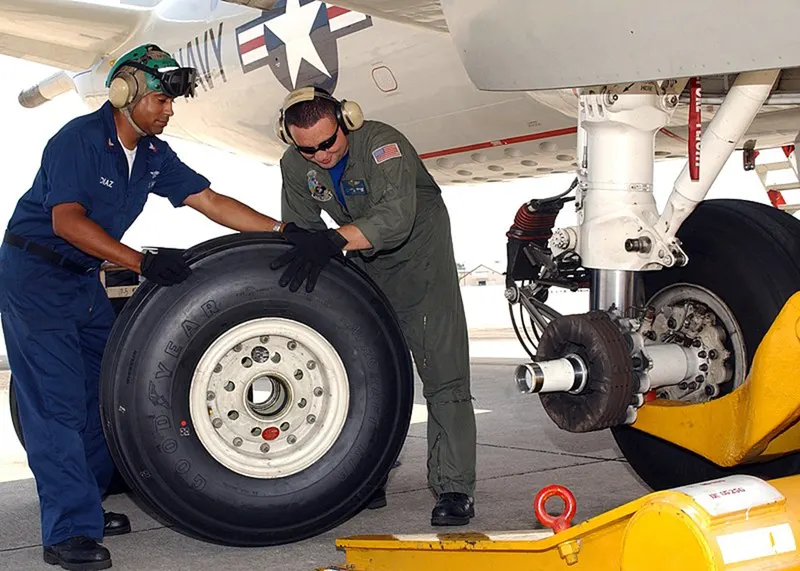
Each of the twelve Boeing 777-300ER main tires is inflated to 220 psi (15 bar; 1,500 kPa), weighs 120 kg (260 lb), has a diameter of 134 cm (53 in) and is changed every 300 cycles while the brakes are changed every 2000 cycles. Each tire is worth about $5,000. Aircraft tires generally operate at high pressures, up to 200 psi (14 bar; 1,400 kPa) for airliners, and even higher for business jets. The main landing gear on the Concorde was typically inflated to 232 psi (16.0 bar), whilst its tail bumper gear tires were as high as 294 psi (20.3 bar). The high pressure and weight load on the Concorde tyres were a significant factor in the loss of Air France Flight 4590.
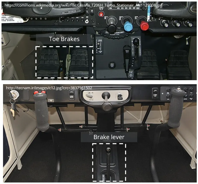
- Brake Forces When Landing
Airplanes rely on a braking system to safely land on runways. At cruising altitude, most commercial airplanes fly at a speed of roughly 500 to 600 mph. When landing, however, they must reduce their speed. A typical 747, for instance, has a landing speed of about 160 to 170 mph. And upon touching the runway, airplanes must quickly brake until they come to a complete stop. How do airplanes brake when landing exactly?
Wing Spoilers:
Many airplanes use wing spoilers to assist with braking when landing. Not to be confused with ailerons, spoilers are extendable flaps on the ends of an airplane’s wings. Pilots can raise the spoilers to decelerate the airplane as it approaches the runway. And even while on the runway, pilots will typically leave the wing spoilers raised. Raised wing spoilers create drag, which essentially slows down the airplane so that it’s able to brake more quickly.
Disc Brakes:
In addition to wing spoilers, airplanes use disc brakes. Airplane disc brakes are similar to the braking system in automobiles. They consist of a pair of calipers that, when engaged, squeeze pads against the rotors of an airplane’s landing gear.
Disc brakes are designed to remain static at all times. In other words, they don’t rotate with the wheels of an airplane’s landing gear. As the wheels turn, the disc brakes will remain static and stationary. They are a vital component of an airplane’s braking system because they are designed to apply pressure to the airplane’s wheels. Disc brakes will squeeze the wheels, thereby slowing down the speed at which they spin. In turn, this reduces the speed of the airplane so that it can come to a complete stop on the runway.
Reverse Thrust:
Finally, many jet airplanes use reverse thrust to assist with braking during landings. Reverse thrust is a feature in jet engine airplanes that, as the name suggests, involves the reversal of the engines’ thrust. When flying, the thrust is projected out the rear of an airplane’s engines. When landing, however, pilots may use the reverse thrust feature. Reverse thrust changes the direction of the engines’ thrust. Rather than projecting out the rear, the thrust will be projected out the front. This reversal of thrust provides deceleration that allows airplanes to slow down more quickly when landing.
Reference:
Take-off power:
Tyres:
https://www.hemmings.com/hmw/bias-ply-or-radial-tires/
Rolling Resistance:
https://ntrs.nasa.gov/api/citations/19930091658/downloads/19930091658.pdf
Tyre Pressure:
https://www.dunlopaircrafttyres.co.uk/technical/pressure/
https://en.wikipedia.org/wiki/Aircraft_tire
Braking of Aircraft:
https://monroeaerospace.com/blog/how-do-airplanes-brake-when-landing/
____________________________________________________________________________________________________________________
Aim: Powertrain for aircraft in runways
Part B:
- A. With necessary assumptions, calculate the force and power required to push / pull an aircraft by a towing vehicle.
- Develop the model for the calculated force and power using Simulink.
- A. Design an electric powertrain with type of motor, it’s power rating, and energy requirement to fulfil aircraft towing application in Simulink. Estimate the duty cycle range to control the aircraft speed from zero to highest. Make all required assumptions. Prepare a table of assumed parameters. Draw a block diagram of powertrain.
(Hint: DC7 Block)
- Also, Design the parameters in excel sheet.
_____________________________________________________________________________________________________________________
- A. With necessary assumptions, calculate the force and power required to push / pull an aircraft by a towing vehicle.
The rolling resistance for the air plane can be calculated as
Rolling Resistance force acting on plane can be calculated as,
Frr = μrr × mg . . . . . . . . . . . .(1)
Where,
Frr = rolling resistance (N)
μrr = rolling resistance coefficient
m = rolling mass (kg)
g = acceleration of gravity (9.81 m/s2)
If the mass of a plane is 40000 kg and the rolling resistance co-efficient between the aircraft wheel and the runway is 0.02
Frr = 0.02 (40000 × 9.81)
Frr = 7848 N
The friction for the puller can be calculated to
Ff = μ W
= μ m g
Where,
Ff = frictional force (N)
μ = friction coefficient
W = Weight (N)
mf = friction mass (kg)
The friction coefficient between a pulling truck rubber wheels and dry runway is 0.9. Since pulling trucks are connected to air crafts nose wheels close to runway, we simplify the calculation of required truck mass
mf = Ff / μ × g
mf = (7848 N) / (0.9 × 9.81 m/s2)
mf = 889 kg
Taking radius of the wheel R as 0.3m
The torque is given by
T = FR
T = 7848 × 0.3
T = 2354 N-m
The power for pulling/push the aircraft can be calculated as
P = F×V
V = Velocity of pull vehicle taken as 5 km/hr
V = 1.388 m/s
P = 7848 × 1.388
= 10893 W
P = 10.89 kW
Reference:
https://www.engineeringtoolbox.com/plane-pull-force-people-d_2083.html
_____________________________________________________________________________________________________________________
SIMULINK Code:
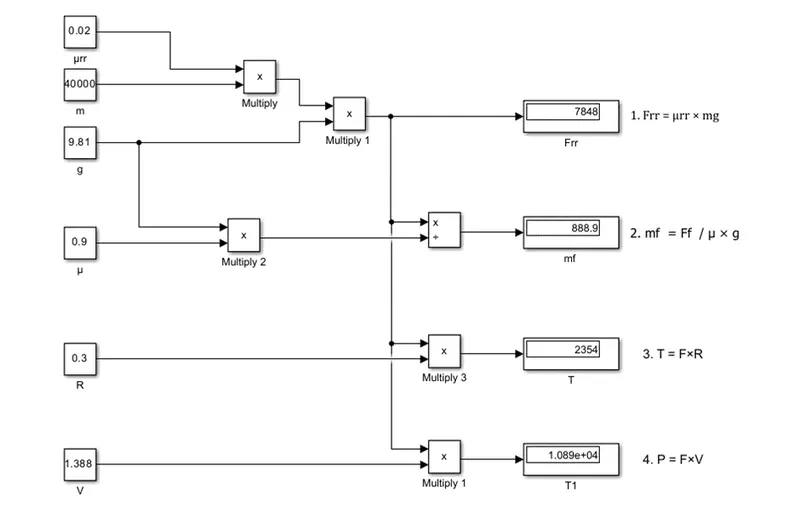
Blocks Used:
- Constants
- Product
- Divide
- Display
Reference:
Simulink Model Link:
https://drive.google.com/file/d/1PqE0KbnMSHbR4puW-VuXSEHDmW9b9ZZR/view?usp=sharingBottom
_____________________________________________________________________________________________________________________
- A. Design an electric powertrain with type of motor, it’s power rating, and energy requirement to fulfill aircraft towing application in Simulink. Estimate the duty cycle range to control the aircraft speed from zero to highest. Make all required assumptions. Prepare a table of assumed parameters. Draw a block diagram of powertrain.
Taking the previous example power value 10 kW for this problem
Power = 10 kW
The motor power should be greater than or equal to 10kW assuming it as 10 kW.
The energy required can be calculated as
E=P×t assuming taxi time of 5 mins.
E = 10 × (5 × 60) kJ
= 3000 kJ
From power equation
Vo × Io = η × Vi × Ii
where,
Vo is the output voltage
Io is the output current
η is the power efficiency (ranging from 0 to 1)
Vi is the input voltage
Ii is the input current
Consider DC input voltage as 48V and Power as 12kW
P = Vi × Ii
12000 = 48 ×Ii
Ii=250A
The efficiency is calculated as
η = 10000/12000
= 0.83
From the above power equation
Vo × Io = η × Vi × Ii
Vo × 250 = 0.83 × 48 × 250
Vo = 40 V
The Vout = Vin / 1-D
40=48/(1-D)
D= 0.2 the duty cycle has in the range of (0,0.2)
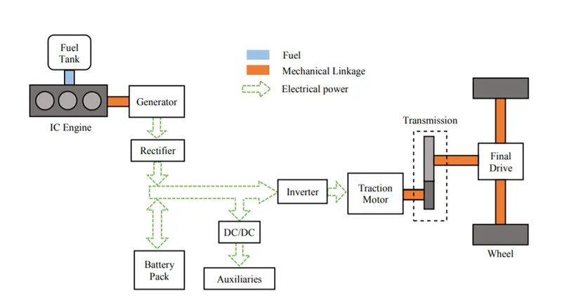
Block Diagram of Power Train:
B. Also, Design the parameters in excel sheet.
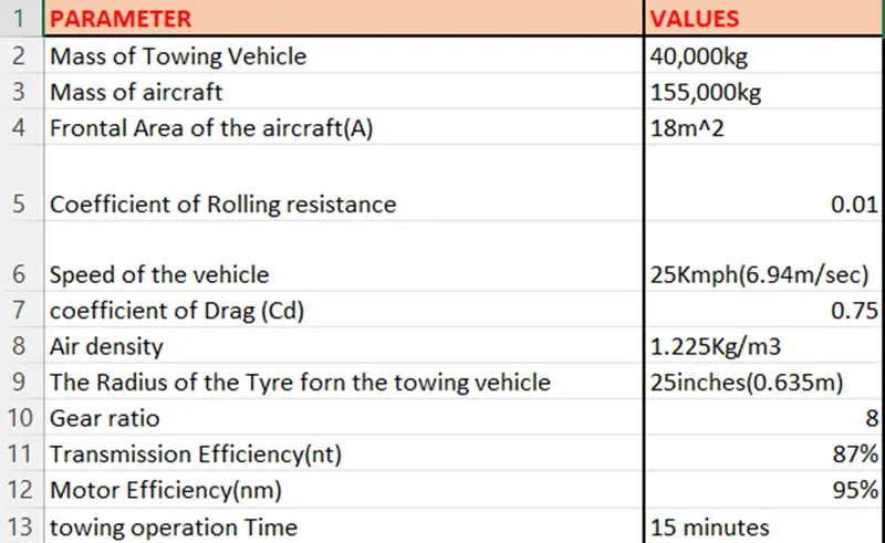
Reference:
https://d-nb.info/1136078681/34
https://www.grc.nasa.gov/WWW/K-12/airplane/powert.html
_____________________________________________________________________________________________________________________