Project-1: Powertrain for aircraft in runways
Objective: To answer the following questions appropriately,
- Search and list out the total weight of various types of aircraft.
- Is there any difference between ground speed and airspeed?
- Why is it not recommended to use aircraft engine power to move it on the ground at the Airport?
- How an aircraft is pushed to the runway when it's ready to take off?
- Learn about take-off power, tyre design, rolling resistance, tyre pressure, brake forces when landing.
- With necessary assumptions, calculate the force and power required to push/pull an aircraft by a towing vehicle.
7. Design an electric powertrain with the type of motor, it’s power rating, and energy requirement to fulfill aircraft towing application. Estimate the duty cycle range to control the aircraft speed from zero to highest. Make all required assumptions. Prepare a table of assumed parameters. Draw a block diagram of the powertrain.
Explanation:
- Search and list out the total weight of various types of aircraft. The answer for this question is prepared in the presentation format. The image snippets are placed below and the presentation is attached for your reference. Below is the general classification of the aircraft.
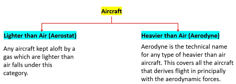
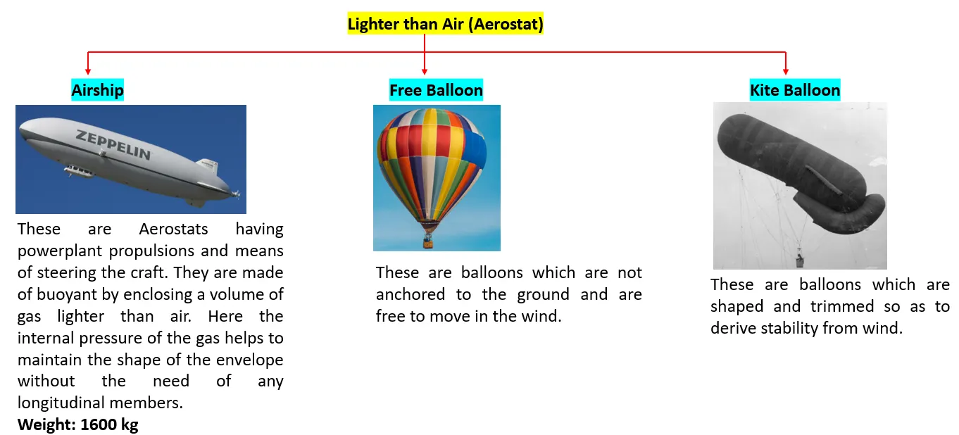
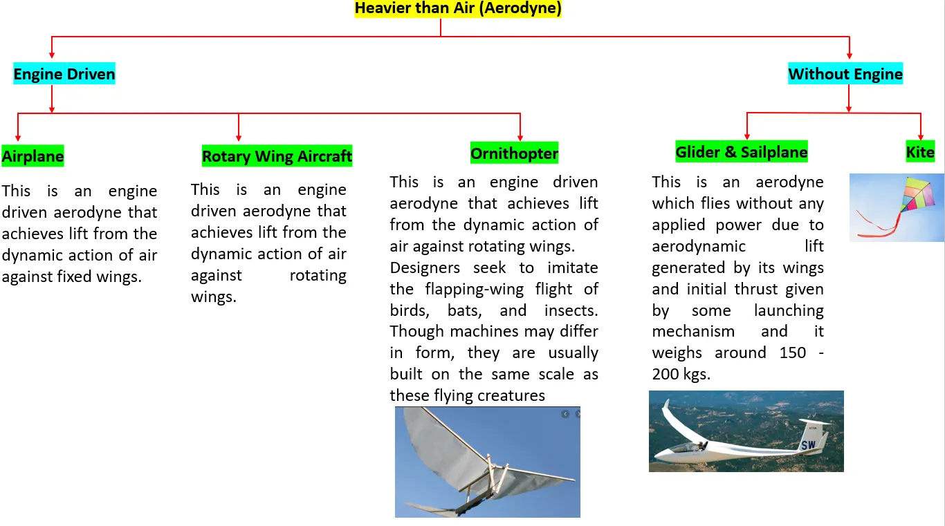
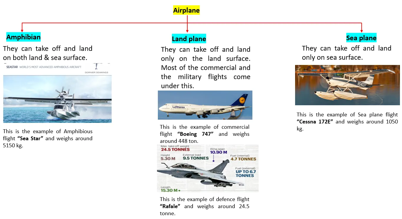
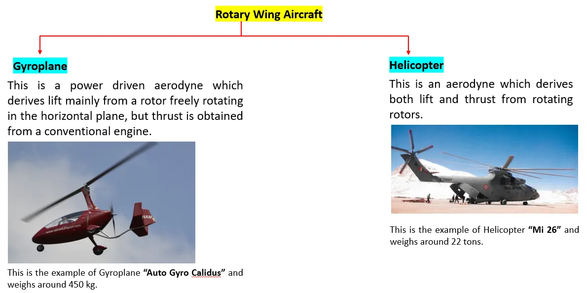
This is an Overview of the different types of aircraft. the list is not exhaustive, as the aircraft still can be classified in to many categories based on the types of engines (type, number), number of wings, mach number, range, payload, source of power and the list goes on.
2. Is there any difference between ground speed and airspeed?
Yes there is difference between the ground and the air speed.
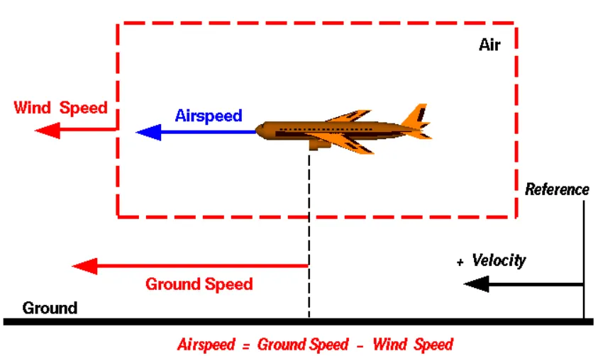
With reference to the above image, I'm going to differentiate the ground speed and the airspeed.
Ground speed is the aircraft speed relative to the ground that it explains how speed can aircraft travel in the ground. It is not dependent on the airspeed.
Here Airspeed is the relative motion between the object and the air. This is also an important parameter for aerodynamic lift generation. This air speed of the object cannot be measured directly from the ground, it depends upon the ground and the wind speed, in fact it is the "vector difference" between the ground and wind speed. (As shown in the above figure).
On a perfectly still day, the airspeed is equal to the ground speed. But if the wind is blowing in the same direction that the aircraft is moving, the airspeed will be less than the ground speed.
3. Why is it not recommended to use aircraft engine power to move it on the ground at the Airport?
"Taxiing" refers to the aircraft movement while on the ground under its own power. This term excludes the accelerating run before take-off and the decelerating run after landing.
The jet engine used is generally not preferred as the primary thrust for taxiing because a large amount of fuel is wasted while the aircraft is still on the ground which could have been used for flying. Since the cost of fuel is one of the biggest expenses in the airline business, many companies are planning to switch to electric taxiing to save fuel and reduce emissions.
There are 2 more important reasons,
i) If the high mounted engines are powered there is a huge risk of the jet blast which may affect the surrounding building and the environment.
ii) In case of low mounted engines are turned on there is a higher possibility of any gravel or other impurities lying in the ground may enter the engine and damage it.
Here is where Pushback trucks &Electric taxiing systems use electric motors fitted inside the wheels of the aircraft’s landing gear. Electric power is supplied to these motors by an on-board Auxiliary Power Unit (APU). This innovative new approach enables airplanes to move backward and forward solely under electric power. This way, aircraft can avoid reliance on main engines for traversing the airport taxiways while burning fuel unnecessarily.
4. How an aircraft is pushed to the runway when it's ready to take off?
As explained in the previous answer, "Taxiing" refers to the aircraft movement while on the ground under its own power. This term excludes the accelerating run before take-off and the decelerating run after landing.
So we know the repercussions that might occur when the engine is used on the runway. So Pushback seemed to be a widely popular option for rolling the aircraft on the runway.
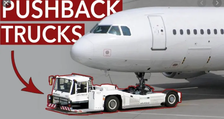
Pushback means the movement of an aircraft from nose-in parking stand using the power of a specialized ground vehicle attached to or supporting the nose landing gear. Conventionally a tow bar is a link used between the aircraft and Pushback tug.
Since the pilots have limited vision from the cockpit what lies behind & side of the aircraft, most of the steering will be done by the driver in Pushback.
5. Learn about take-off power, tyre design, rolling resistance, tyre pressure, brake forces when landing.
Take-off power: It is the phase where the flight leaves the ground and becomes airborne.
Take off performance can be predicted using a simple measure of the acceleration of the aircraft along the runway based on force equilibrium.
The forces involved will be,
T – Thrust of propulsion system pushing aircraft along runway.
D – Aerodynamic Drag of vehicle resisting the aircraft motion.
F – Rolling resistance friction due to the contact of wheels or skids on the ground.
During take-off run the imbalance in these forces will produce an acceleration along the runway
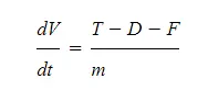
where dV/dt is the acceleration along the runway and m is the mass of the vehicle.
Rolling resistance:
The friction between aircraft and runway will be proportional to the normal force exerted by the aircraft on the runway.
The normal force will be the difference between Weight of aircraft and Lift, the friction coefficient will be typically of a magnitude of 0.02 for a standard tarmac runway.
Tyre Design:
When it comes to safety, tyres are one of the most important components of aircraft. They help to absorb the shock of landing and provide cushioning. It also provides the necessary traction for braking and stopping of an aircraft.An aircraft tyre is designed to withstand extremely heavy loads while landing, take off, taxing, and parking. The number of wheels required for aircraft increases with the weight of the aircraft, as the weight of the aeroplane needs to be distributed more evenly.
Carcass plies are used to form the tire. They are sometimes called casing plies. An aircraft tyre is constructed for the purpose it serves.
- They support the weight of an aircraft while it is on the ground.
- It also provides the necessary traction for braking and stopping of an aeroplane.
- Tyre also helps to absorb the shock of landing and provide cushioning the roughness of takeoff, roll-out, and taxi operations.
Unlike an automobile or truck tyre, it does not have to carry a load for a long period of continuous operation. However, an aircraft tyre absorbs the high impact loads of landing, and also it’s operating at high speeds for a short time when required.
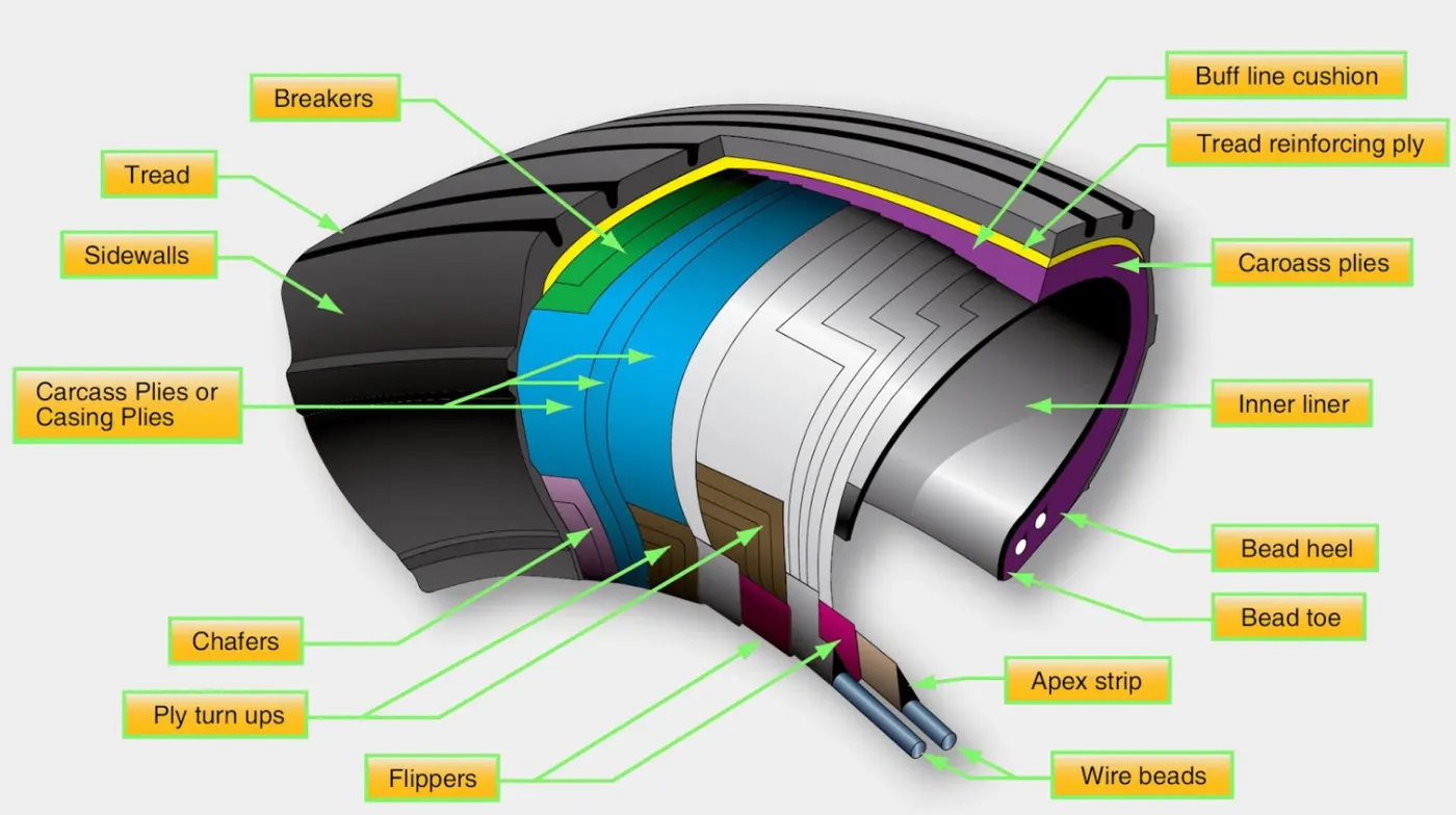
Bead
Carcass Plies
Tread
Sidewall
Tire Pressure: The pressure usually operates at higher pressure up to 200 psi for domestic and as well international flights which are usually heavier.
Brake forces when landing:
There are three kinds of braking forces that can be employed in the aircraft to decelerate it in the run way.
1. Engine power: The most important action to achieve deceleration from a speed at which the engines are still producing forward motion is to select all thrust/power levers to the ground idle position promptly, and if available, continue the action through to the selection of reverse thrust or reverse propeller pitch. Thrust reversers and reverse propeller pitch are most effective at high speeds.
2. Wheel brakes: To be effective, braking action at any speed depends upon sufficient friction existing between the tires and the runway surface achieved through freely rotating wheels.
3. Mechanical spoilers:
The mechanical deflection of parts of the wing upper surfaces and tail cone assembly can assist deceleration in two ways:
- Directly, by increasing aerodynamic drag on the moving aircraft. This can be achieved by raising upper wing surface panels called ground spoilers or by operation of a tail cone ‘clamshell’ type air brake.
- Indirectly by increasing the effective downward load on the landing gear and thereby increasing the efficiency of wheel braking.
6. With necessary assumptions, calculate the force and power required to push/pull an aircraft by a towing vehicle.
Here the pushback trucks experience two kinds of forces acting on them when they try to push/pull the aircraft.
i) Rolling resistance force
ii) Aerodynamic drag force
Rolling resistance force - The formula used for the rolling resistance force is mentioned below,
Frr = u*m*g
where u is the coefficient of rolling resistance, m is the mass and g is the acceleration due to gravity.
This rolling resistance force acts on both the pushback truck and the aircraft.
so first considering the aircraft, u = 0.02, m = 40,000 kg
Frr (aircraft) = 0.02*40000*9.81 = 7848 N
and Now considering for the Pushback truck, u = 0.09, m = 1000 kg
Frr (pushback truck) = 0.09*1000*9.81 = 883 N
Therefore the total resistance will be the sum of the aircraft & pushback truck rolling resistance = 7848 + 883 = 8731 N
Aerodynamic force - The aerodynamic force to move an airplane on an absolute flat runway with no wind at constant low speed is usually very negligible.
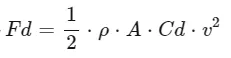 , where 'p' is the ai density kg/m^3, A is the front area in m^2, Cd is the drag coefficient and v is the velocity in m/s.
Since the aerodynamic force is very negligible here, the net force acting on the pushback truck during the push/pull of an aircraft, Fnet = Frr (pushback truck) + Frr (aircraft) = 8731 N
The power required is,
P = F*V , V is the velocity in m/s by which pushback truck either pushes or pulls the aircraft
P = 8731*9.72 = 84.86 KW
References: https://www.engineeringtoolbox.com/plane-pull-force-people-d_2083.html
7. Design an electric powertrain with the type of motor, it’s power rating, and energy requirement to fulfill aircraft towing application. Estimate the duty cycle range to control the aircraft speed from zero to highest. Make all required assumptions. Prepare a table of assumed parameters. Draw a block diagram of the powertrain.
As we discussed above An aeroplane pushback vehicle is required to move aeroplanes away from airport terminals. Powertrain is a system which covers the all the drive train components which propels the vehicle in the road.
Here an all wheel Drive EV push back vehicle is considered.by using in-wheel motors in each wheel of vehicle better wheel propulsion can be achieved, ensuing increase of efficiency and better power saving of the whole system. This approach adds to controllability of each individual wheel and decreasing weight of chassis [1]. By proper control of each wheel, it is possible to achieve a better acceleration, torque control and regenerative braking.
Implementation of Antilock Braking System (ABS), Collision Avoidance System (CAS), by-wire steering and better overall Dynamic Stability Control are much simpler using four inwheel Motors.
The pushback vehicle must be able to generate a large towing tractive force, but also have a relatively high top speed to travel quickly between pushback operations (~30 kph unloaded).
The block diagram of the EV drive train
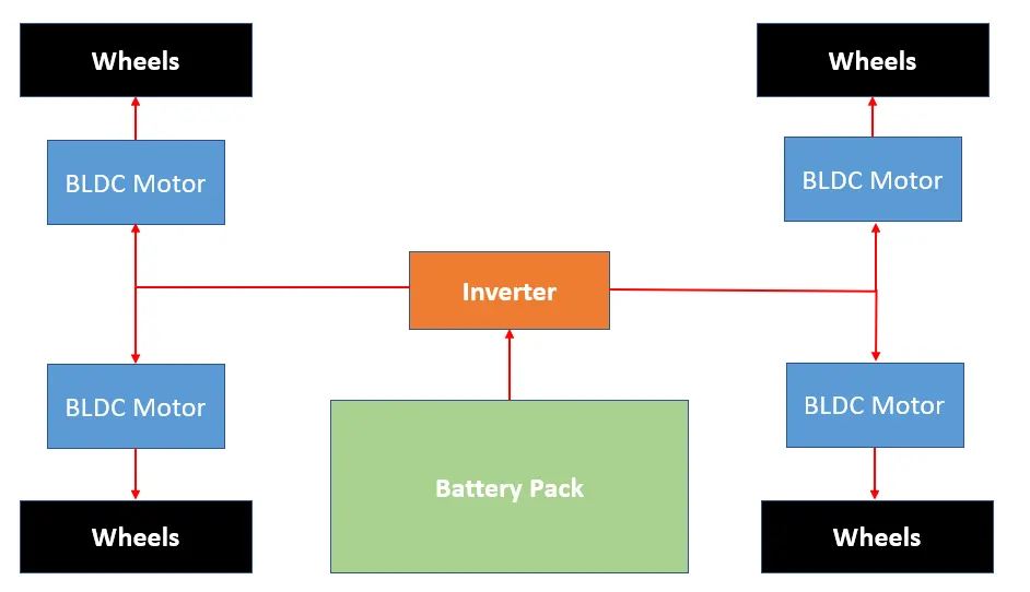
For Tow & Maintanence the motor requires high torque and low speed and for carrying the solo motor requires low torque and high speed.
In the question it is mentioned as Electric pushback truck, so following are the main components that we are going to discuss about
i) Battery
ii) Power converter
Battery: For the EV to be truly comparable to the ICE counterpart, the SOE of the battery pack should be full at the end of the duty cycle. This would be similar to the ICE vehicle having its fuel tank filled at the end of a working dayTraction battery voltage should reflect the best design for duty cycle, vehicle speed, tractive effort, and minimum current losses.
Traction Motor: Normally the Pushback Vehicle would not be held to conventional passenger vehicle development criteria, i.e. fast 0-60mph acceleration times or to be able to reach motorway cruising speeds. This is because aeroplane manufacturers impose low acceleration limits for towing operations to prevent damage to the landing gear and there are speed limits enforced on working airfields for ground support vehicles.
Here I'm considering the BLDC motor because of better torque -speed characteristics, higher efficiency, high output power to size ratio (due to absence of windings on rotor), higher dynamic response (due to low inertia of rotor), higher operating life, lower maintenance because of absence of brushes, noiseless operation and higher speed ranges are immediate advantages of BLDC motors over Brushed DC and Induction Motor. Higher output power to size ratio of BLDC makes it suitable for EV applications, where, space and weight are significant considerations and less maintenance is obligatory. Noiseless operation of BLDC motor also makes it more convenient to have integral motor of BLDC.
Assumed Duty cycle for the Pushback Vehicle: (Source: IET A New Traction Motor Sizing Strategy for a EV based on an Overcurrent tolerantPredictionModel)
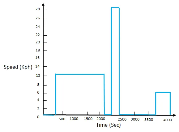
Duty Cycle of an Pushback Vehicle:
An aeroplane pushback vehicle is required to move aeroplanes away from airport terminals and occasionally tow them across an airfield for routine maintenance. Therefore, the pushback vehicle must be able to generate a large towing force, but also have a relatively high top speed to travel quickly between pushback operations (~30 kph unloaded).
Assumed Vehicle parameters: (Source: IET-ANewTractionMotorSizingStrategyforaHEVEVbasedonanOvercurrent-tolerantPredictionModel)
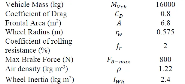
From the above the assumed data we can figure out the maxmium power and torque needed for the Pushback vehicle.
The maximum Traction force = Rolling resistance force + Aerodynamic force + brake force
Rolling resistance force, Frr = u*m*g = 2*16000*9.81 = 3,13,920
Aerodynamic force, Ad = = 0.5*0.8*6.8*1.22*(4)^2 = 53.1[The velocity is assumed based on the duty cycle data given above]
Total force = 3,13,920+53.1+800 = 3,14,773 N
Power = force* velocity = 3,14,773*4 = 1259 kW
Maximum Torque on wheels = 0.575*3,14,773 = 180 kNm