Project-1: Powertrain for aircraft in runways
EV Live Batch 21.
1 Aim:
Part A: 1 .Search and list out the total weight of various types of aircrafts.
Ans:
1 Antonov 225 Mriya: The Antonov An-225 Mriya is a six engine, strategic heavy lift cargo transport aircraft designed and manufactured by the Antonov Design Bureau (ADB) of Ukraine. The term Mriya refers to the word dream or inspiration in English. Its NATO reporting name is Cossack.
=> The aircraft was derived from the An-124 Ruslan (NATO: Condor). Cossack is the heaviest fixed wing aircraft in the world to carry 640t of cargo. It is bigger than an Airbus 380 airliner, the An-124 and the Boeing 747 Freighter.
=> The Cossack features an airborne cargo handling system and a cargo door fitted with a ramp to carry out loading or unloading missions quickly and easily. It also features a fuselage barrel extension on the front and rear of the wings to increase the span. The load securing system attaches uniquely size cargoes to the upper fuselage section.
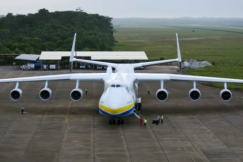
=> This Weight of plan Antonov An-225 Mriya : 640 t (710 short tons; 630 long tons).
2.Boeing 747-8F: The Boeing 747-8F is the all-cargo version of the 747-8F airplane by Boeing. It is a development of the 747-400, with a new engine, new wings, a longer fuselage and an increased wing span among other adjustments. It is the only commercial in-production cargo airplane with a nose door, allowing for a flexible and efficient loading of XL cargo shipments. The airplane can carry a payload of 139 tonnes with a volume of (24462 ft³) in the main cargo deck. The 747-8F can carry 16% more revenue cargo volume and provides 17% more fuel-efficiency than its predecessor.
=> The aircraft uses many of the technologies developed for the 787 Dreamliner, including the engines, interior configuration, flight deck technologies and instrumentation and wing configuration. These provide significant increases in passenger and freighter capabilities, improved fuel efficiency, reduced noise and emissions and improved operating economics.
=> The aircraft uses the same pilot type ratings as the 747, many existing 747 spares, services and the majority of the ground support equipment.
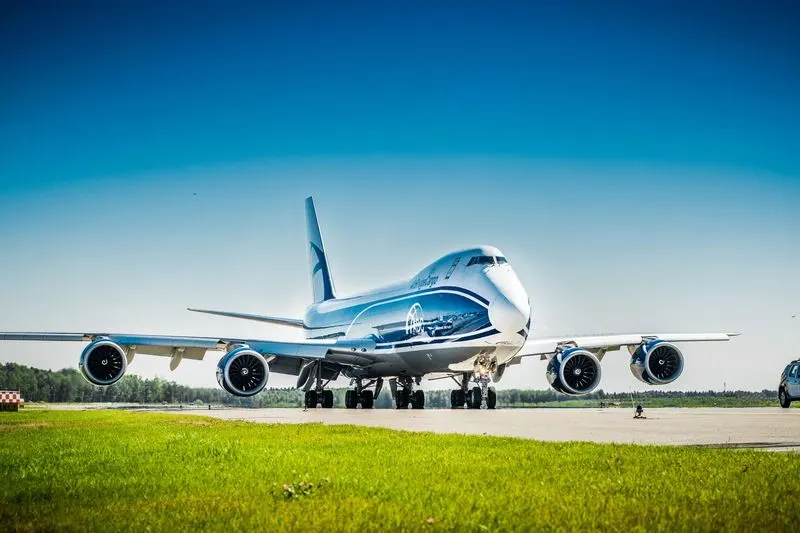
=> This Weight of plan Boeing 747-8F :975,000 lb (442 t).
3.vertical takeoff and landing (VTOL) aircraft: VTOL aircrafts' ability to take off and land vertically as well as hover, fly slowly and land in small spaces distinguishes it from the conventional aircraft. Also, the most recent VTOL aircrafts in development use electric motors or batteries instead of fuel, designating them electric vertical takeoff and landing (eVTOL) aircrafts.
=> A rotary wing aircraft (or rotorcraft) uses lift created by rotor blades spinning around a central mast. Some examples of rotorcrafts are:
- Helicopter – The helicopter's spinning rotors create thrust like a large propeller that is directed vertically, enabling it to lift off. While in flight, a slight tilt in the desired direction pushes some of the aircraft's thrust and sends the craft forward.
- Gyrodyne - The gyrodyne is also known as a compound helicopter because it has the powered rotor of a helicopter, but a separate forward thrust system
- Cyclogyro - On the cyclogyro, the rotary wing's axis and surfaces remain sideways across the airflow, similar to a conventional wing.
=> Powered-lift aircraft takeoff and land vertically but behave differently than rotorcrafts while in flight. They often have a fixed-wing design. Some examples of powered-lift aircraft are:
- Convertiplane - The convertiplane relies on the rotor for lift when taking-off, but then switches to a fixed-wing lift while in flight.
- Tiltrotor - The tiltrotor, also known as a proprotor, moves its propellers or rotors vertical to achieve VTOL and then tilts them forwards while flying for horizontal wing-borne flight; the main wing remains fixed in place.
- Tailsitter - The tailsitter aircraft sits vertically for takeoff and landing, but, once in the air, the whole craft tilts forward to achieve horizontal flight.
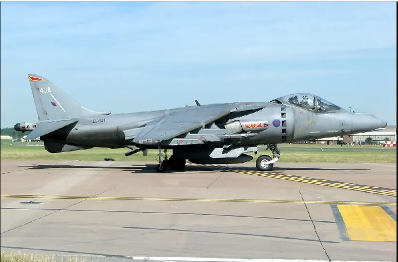
=> This Weight of plan VTOL aircrafts:975,000 lb (442 t).
4.Aerobatic Cruisers: The lowest-power Citabrias of which we are aware have 100 HP, while the highest have 180 HP up front (there are only a few 180-HP Citabrias in the field). All are fabric-covered, and have fixed-pitch props; some have wing flaps, the others don’t and all are aerobatic, have tandem seating, are soloed from the front and use a stick rather than a yoke. The 7KCAB model has an inverted fuel and oil system.
=> The flight controls are not well-harmonized. The elevators and rudder are “just right,” while the ailerons are way too heavy and the roll rate slow. We consider spades, which look like small shovels and are attached to the ailerons to reduce control forces, to be a nearly essential mod.
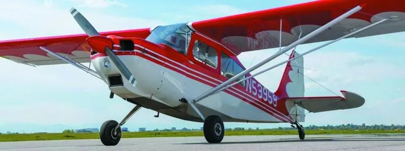
=> This Weight of plan Aerobatic Cruisers:1,155 pounds empty and it is almost 18 feet long.
5.MiG-35 Fighter Airforce: MiG-35 is a new export variant that combines the modern systems of the MiG-29M2 with an AESA radar and manufactured by Mikoyan. The fighter plane has the thrust vectoring of the MiG-29OVT as an additional option.
=> Improved avionics and weapon systems, notably the new AESA radar and the uniquely designed optical locator system (OLS), make the aircraft less dependent on ground-controlled interception (GCI) systems and enables the MiG-35 to conduct independent multirole missions.
=> The final version of MiG-35 was displayed for the first time at Aero India 2007. The prototype of the MiG-35 had been shown to the public in 2005 at air shows in Russia and the UK.
=> The MiG-35 is powered by two RD-33MKBs that can be fitted with KliVT swivel-nozzles and a thrust vectoring control (TVC) system. The MiG-35’s combination of TVC and advanced missile-warning sensors gives it the edge during combat. RD-33 engines generate 7% more power compared to the baseline model due to the modern materials that go into the manufacturing of the cooled blades. The engines provide a higher-than-average thrust of 9,000kgf.
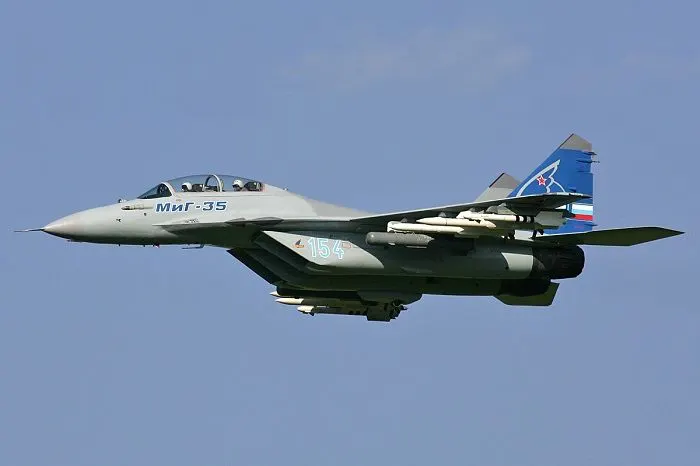
=> This Weight of plan MiG-35 Fighter Airforce: 19,000 kg.
2 Aim: Is there any difference between air speed and ground speed ?
Ans:
(i)Air Speed: The airspeed indicator (ASI) or airspeed gauge is a Flight instrument indicating the of an air speed in kilometer per hour (km/h), knots (kn), miles per hours (MPH) and/or meter per second (m/s). The recommendation by icao is to use km/h, however knots is currently the most used unit. The ASI measures the pressure differential between static pressure from the static port, and total pressure from the pitot tube This difference in pressure is registered with the ASI pointer on the face of the instrument.
=> It is split into two ways:
- Cruising speed or ground speed : It is the speed of air craft with respect to the ground where the aircraft flying in air at its max speed.
- Air Speed: It is the speed of aircraft relative to the wind.
=> ICET : Integrated Common Entrance Test.
=> Indicated Airspeed (IAS)-direct reading from the face of the instrument.
=> Calibrated airspeed (CAS) - IAS corrected for position and installation error 5-8B19.
=> Equivalent airspeed (EAS) -cas corrected for compressability.
=> True airspeed (TAS) -EAS corrected for altitude, temperature.
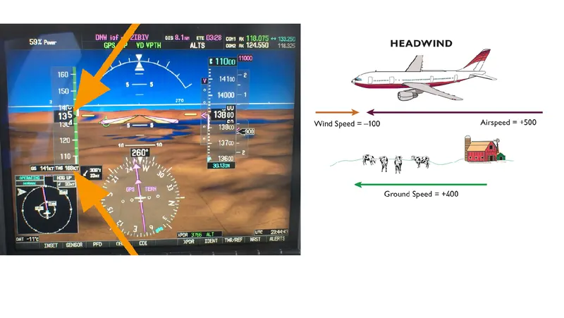
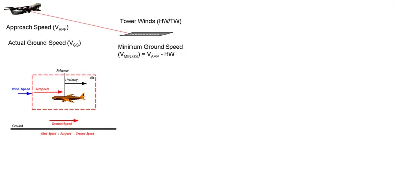
(ii) Ground Speed: The relationship between airspeed and ground speed is fairly simple. Ground speed is simply the sum of airspeed and wind speed.
=> If the aircraft is flying in the same direction as the wind is blowing, the aircraft experiences tailwind, and its ground speed is higher than its airspeed. On the other hand, if the wind is blowing against the direction the aircraft is traveling in, the aircraft experiences headwind, and its ground speed is lower than its airspeed.
=> An aircraft diving vertically would have a ground speed of zero. Information displayed to passengers through the entertainment system of airline aircraft usually gives the aircraft ground speed rather than air speed.
=> Ground speed can be determined by the vector sum of the aircraft's true air speed and the current wind speed and direction; a headwing subtracts from the ground speed, while a tailwind adds to it. Winds at other angles to the heading will have components of either headwind or tailwind as well as a crosswind component.
=> Ground speed:
* Actual speed of the aircraft over the ground.
* True airspeed adjusted for the wind.
* Found using the E6B.
3 Aim: Why is it not recommended to use aircraft engine power to move it on the ground at Airport?
Ans:
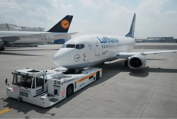
The TV show Fifth Gear once featured a (slightly modified) Volkswagen Touareg SUV pushing a Boeing 747, but road vehicles are less than ideal for the job. Pushback tugs don’t necessarily have to be more powerful than normal trucks in terms of horsepower, but they do need a very high torque to move fully loaded aircraft weighing hundreds of tons.
=> Single runway : When using this layout, airport engineers will orient the runway so aircraft can take advantage of prevailing winds.
=>Parallel runways : The distance between the two runways depends on the size and number of aircraft using the airfield. Close parallels have less than 2,500 feet between runways; intermediate parallels are between 2,500 and 4,300 feet (762 and 1,310 meters) apart; and far parallels are greater than 4,300 feet apart. Dual-line layouts feature two sets of parallels spaced 4,300 feet apart.
=> Open-V runways : Two runways that converge but don't intersect make an open-V layout. This arrangement gives air traffic controllers greater flexibility as they maneuver planes on the runways. For example, if no wind is blowing, they'll use both runways. But if the wind becomes strong in one direction, they'll shut down one runway and use the one that allows planes to take off into the wind.
=> Intersecting runways : Runways that cross each other are common at airports where the prevailing winds can change throughout the year. The intersection point can be in the middle of each runway, near the threshold (where aircraft touch down) or far from the threshold (where aircraft lift off).
=> To determine the length of a runway, airport planners consider a number of factors, including airport elevation, temperature, wind velocity, airplane operating weights, takeoff and landing flap settings and runway surface condition (dry or wet).
=> A typical runway at a commercial airport, which must be able to accommodate jumbo jets, is between 10,000 and 12,000 feet (3,048 and 3,658 meters) long. Runways at small community airports, which serve aircraft with 20 or fewer passenger seats, may only be 3,000 to 4,000 feet (914 to 1,219 meters) long.
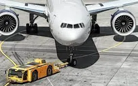
=> Taxiing: (rarely spelled taxying) is the movement of an aircraft on the ground, under its own power, in contrast to towing or pushback where the aircraft is moved by a tug. The aircraft usually moves on wheels, but the term also includes aircraft with skis or floats.
=> An airplane uses taxiway to taxi from one place on an airport to another; for example, when moving from a hanger to the runway. The term "taxiing" is not used for the accelerating run along a runway prior to takeoff, or the decelerating run immediately after landing, which are called the takeoff roll and landing rollout, respectively.
=> Electric taxiing systems use electric motors fitted inside the wheels of the aircraft’s landing gear. Electric power is supplied to these motors by an onboard Auxiliary Power Unit (APU). This innovative new approach enables airplanes to move backward and forward solely under electric power. This way, aircrafts can avoid reliance on main engines for traversing the airport taxiways while burning fuel unnecessarily.
4 Aim: How an aircraft is pushed to runway when its ready to take off?
Ans:
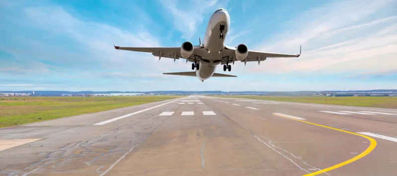
Take off is the phase of the flight in which an aeroplane leaves ground and becomes airbone.For lighter aircraft full power is given durong take off where as on the other hand large cargo carriers aircraft make use of less power during take off inorder to inrease the life span of engine,reduce maintenance cost ,reduce engine heat and also for a smooth take off flight.
=> The pilot parks the aircraft in exactly the right place. Usually with the help of an automatic system, but occasionally guided by a marshaller waving two paddles or wands. Dozens of handling personnel are already standing by to perform a whole range of tasks simultaneously.
=> As soon as the aircraft is stationary and the engines are switched off, the first priority is to disembark the passengers as quickly as possible. The apron handler places chocks in front of the wheels and connects the ground power. Meanwhile, the passenger bridge manoeuvres up to the door and a belt loader rolls up to the cargo hold. Luggage is unloaded and transferred to the terminal on baggage carts.
=> Refuelling begins, usually from a hydrant at the stand. A hose is attached to this from a special vehicle called a dispenser, with the other side connected to the fuel tank in the wing. Read more about refuelling.
=> Now it is time to service the aircraft. The caterer loads new meals and takes away the food waste and used cutlery and crockery. Other activities include draining the lavatories, replacing the headrest covers, removing rubbish and distributing fresh blankets and in-flight magazine.
=> A specialist team – or sometimes the crew themselves – cleans the cabin so that the new passengers board a pristine aircraft.
=> Meanwhile, specialists from the airline conduct a technical check to make sure that the engines, wings, control surfaces, landing gear, instruments, doors and other equipment are in full working order.
=> The aircraft is now ready for baggage to be loaded for the next flight. This is a quick process, on average taking only 10-15 minutes. A little later the passengers start boarding. As soon as they are all in their seats, the door is closed and the pilot informs air-traffic control that the flight is ready for departure.
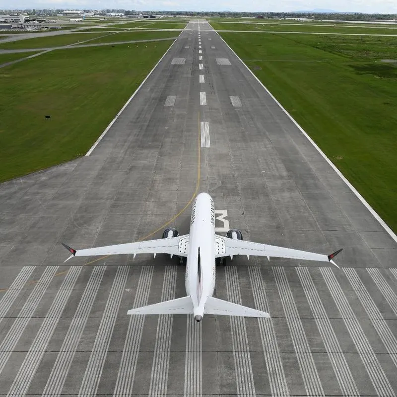
=> The apron handler removes the chocks. A so-called pushback truck reverses the aircraft into taxiing position, pushing it with a towbar attached to the nose-wheel strut. Or, in the most modern versions, by actually lifting the wheel. That speeds up coupling and decoupling.
=> The aircraft taxis to the runway to depart at the agreed time.
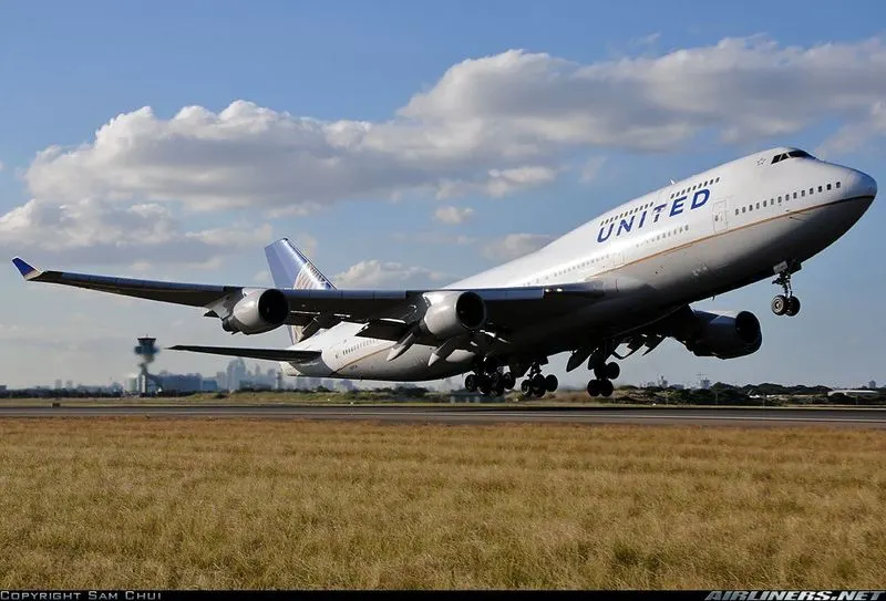
=> The pilot waits for permission to take off from air-traffic control. This is possible once the departure route is clear. As soon as the go-ahead is received, the plane takes to the air at full power.
5 Aim: Learn about take off power, tyre design, rolling resistance, tyre pressure, brake forces when landing.
Ans: The takeoff in any aircraft occurs when the airplane leaves the ground and becomes airborne. However, there is a lot more to it than that. There are a number of things which need to be done in advance, and the takeoff itself is split into a few different stages.
=> This is true of any aircraft, from a small single-engined training airplane to a large passenger carrying airliner. Obviously some of the procedures will be slightly different in aircraft of different sizes and types. In this article, we will take a detailed look at the procedures for a small aircraft, such as is flown by the majority of private pilots.
=> When you go out for a drive, you may well jump in your car and just go. Perhaps you briefly check that you have enough fuel, and maybe you take a cursory look at the tires. But that is probably all that you do.
=> However, there is much more to do before you depart in an airplane. Firstly, there will be a certain amount of paperwork to do. If the pilot is leaving from an airport, he or she will need to sign out, and may need to file a flight plan. If he has passengers, he will need to give them a safety briefing, which will probably be fairly short, but is actually a legal requirement.
=> After this the pilot will need to do his pre-flight checks. The external checks mean that he walks around the aircraft, following a checklist and taking careful note of the state of the whole machine, from wings to other moving surfaces to fuel state. This is very important. After all, if anything is wrong, he cannot just stop in the air and get it sorted, in the same way as you stop in a car by the side of the road. So he needs to make sure of everything in advance.
=> After that the pilot climbs aboard, helps the passengers do so, and ensures everyone is safely strapped in and that there are no loose articles around. Then there are a large number of internal checks to be completed, some before switching on the engine, some done with the engine running, and some at full power. Again, the pilot needs to ensure that everything is working as it should before departure.
=> The pilot will then call on the radio, saying he is ‘ready to taxi’.
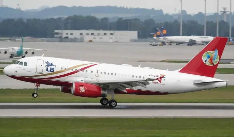
=> Taxi-ing the aircraft involves moving it along the ground from where it has been parked, up to the start of the runway. During taxi-ing, there are other checks which need to be done, mainly to ensure that the steering on the ground works as it should do.
=> Small aircraft are steered by use of the rudders, with the pilot using his feet on the pedals. The pilot does not use the yoke or stick for this purpose – although it is not unusual to see new trainee pilots attempting to do so! Some aircraft are difficult to steer on the ground, particularly those with a tailwheel. However, there are not that many tailwheel aircraft being flown any more, and most modern aircraft are fairly easy to taxi. Nevertheless, taxi-ing must be done slowly and with care. The wings of an aircraft stick out further than the pilot often expects them to, and accidents during taxi-ing are not that uncommon.
=> When the pilot reaches the start of the runway, or the line of aircraft waiting to take off, he will have a few final checks to do. He will then call on the radio that he is ‘ready for departure’. He never, ever says he is ready for takeoff. This point is so important that we will have a look at how it came about.
5 Aim: Learn about take off power, tyre design, rolling resistance, tyre pressure, brake forces when landing.
Ans:
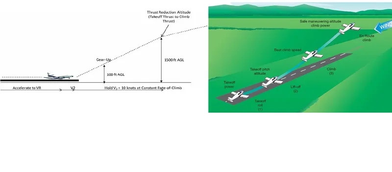
Take Off Power:
=> Take off power can be predicted using a simple measure of the acceleration of the aircraft along the runway based on force equilibrium.
The forces involved will be.
T is Thrust of propulsion system pushing aircraft along the runway.
D is Aerodynamic Drag of vehicle resisting the aircraft motion.
F is Rolling resistance friction due to the contact of wheels or skids on the ground.
During the take-off run, the imbalance in these forces will produce an acceleration along the runway.
m (dv/dt)=T-D-F
where, dv/dt is the acceleration along the runway and m is the mass of the vehicle.
This length will typically be considerably longer than the distance required to achieve rotation (flying) speed. A
rough approximation is that runway total length is around 2. S₁
Therefore, Takeoff power = force displacement = dv dt 2-S1 (T-D-F). Si
Tyre Design: 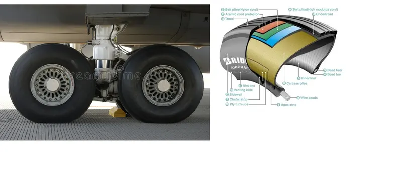
=> Designing aircraft tires is a very intense undertaking The tyre is designed to withstand heavy loads while landing, take off, taxing, and parking.
=> The number of wheels required for aircraft increases with the weight of the aircraft, as the weight of the aeroplane needs to be distributed more evenly.
=> Aircraft tyre generates more heat during landing Aircraft drags the wheel until they match the rotational velocity of wheels. Due to this heat generates.
=> Aircraft's tread pattern is designed to facilitate stability in high crosswind conditions, to channel water away to prevent hydroplaning and for braking effect.
Rolling Resistance:
The friction between aircraft and runway will be proportional to the normal force exerted by the aircraft on the runway.
F= μ(W-L)
The normal force will be the difference between Weight of aircraft and Lift, the friction coefficient will be typically of a magnitude of 0.02 for a standard runway.
Tyre Pressure: Aircraft tires generally operate at high pressures, up to 200 psi (14 bar or 1,400 kPa) for airliners, and even higher for business jets. The main landing gear was typically inflated to 232 psi (16.0 bar), whilst its tail bumper gear tires were as high as 294 psi (20.3 bar). The high pressure and weight load tyres were a significant factor.
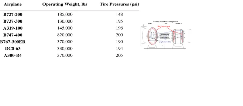
=> Tests of airliner aircraft tires have shown that they are able to sustain pressures of maximum 800 psi (55 bar; 5,500 kPa) before bursting.
=> During the tests the tires have to be filled with water, to prevent the test room being blown apart by the energy that would be released by a gas when the tire bursts.
=> Aircraft tires are usually inflated with nitrogen to minimize expansion and contraction from extreme changes in ambient temperature and pressure experienced during flight.
=> Dry nitrogen expands at the same rate as other dry atmospheric gases (normal air is about 80% nitrogen), but common compressed air sources may contain moisture, which increases the expansion rate with temperature.
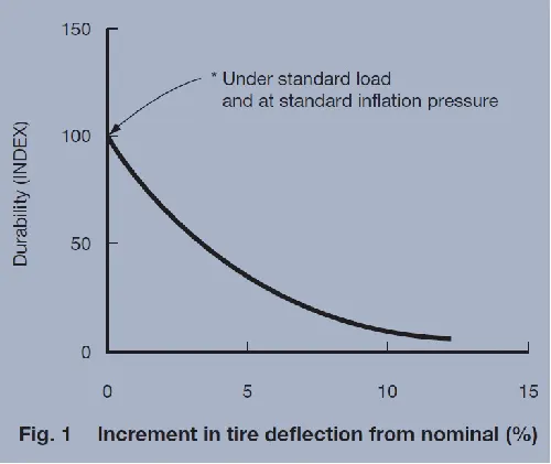
=> The requirement that an inert gas, such as nitrogen, be used instead of air for inflation of tires on certain transport category airplanes was prompted by at least three cases in which the oxygen in air- filled tires had combined with volatile gases given off by a severely overheated tire and exploded upon reaching autoignition temperature.
=> The use of an inert gas for tire inflation eliminates the possibility of tire explosion.
Brake Forces When Landing: The landing run can be calculated in a similar fashion to the take off distance. The aim is again to minimise the distance.
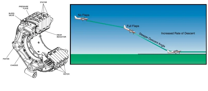
=> The touch down velocity should be approximately the stall speed of the aircraft in landing configuration. This will be achieved by a pitch manoeuvre during the flare portion of the approach which which increase drag an decelerate the aircraft to minimum flying speed. The deceleration on the landing roll from VTD to Vo will be accomplished by braking.
=> And reverse thrust. This can be solved by the average acceleration approach that was used to estimate the take-off roll.
m*(dv/dt) = -T-D-F
=> The negative acceleration or deceleration value will be based on friction coefficient for maximum braking and the value of reverse thrust (if available).
Part B:
7 Aim: A. Design an electric powertrain with type of motor, it’s power rating, and energy requirement to fulfill aircraft towing application in Simulink. Estimate the duty cycle range to control the aircraft speed from zero to highest. Make all required assumptions. Prepare a table of assumed parameters. Draw a block diagram of powertrain.
(Hint :DC7 Block).
Ans: Here we have to take the DC7 model and electrical power train How to find power train output value and duty cycle and Assumed Parameters.
Electrical Power Train With Type Of Motor:
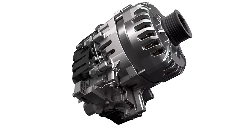
Type Voltage Continuous/Peak Working rotation Max Torque Weight Cooling
Power
1 REB 90 400-800V 60-70KW/80 KW 1500-4000 300NM 22000g Air/Hybrid (air + Fluid)
(RPM)
Estimation Of Duty Cycle:
Based on the calculation done in study 6
The Power Required for towing of the aircraft is 45.26kW.
Motor Considred for the drive train is REB 90
Considering 60kW as continuous power, so the voltage will be 400V
Battery power is considred to be 550v .
Duty cycle is given by Vo/Vb
where Vo is motor required voltage
Vb is battery voltage.
d= 400 550 ⇒ 0.7272
As there will be losses due to the
resistance of FET and Inductance.
Correction factor is considred to be 90%
As there is 10% loss, the voltafge demanded by the motor should be 10% more than required d 0.7272 (1+0.1) 0.799≈ 0.8
so the voltage demand should be around 440V from the battery.
Assumed Parameters:
Mass of aircraft = 575000 kg
Mass of the push back track = 1000 kg
coefficient of rolling resistance = 0.002
Drag coefficient = 0.025
Air density = 1.125 kg/m^3
Frontal Area =150 m^2
Velocity = 4 m/s
uphill gradient = 0 deg
Battery voltage = 550 v
correction Factor = 0.8
Block Diagram Of Electric Power Train:
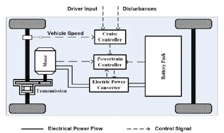
Simulink Model: DC7 Block:
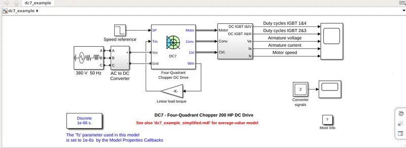
=> Here in this simulink model we take compounds are One 380V505HZ block & speed reference block & one Four- quadrant chopper DC drive block & one AC to DC converter block & one linear load torque block & one selected block & one converter signals block & one scope block & one powergui block from the simulink libray browser.
=> The 200 HP DC motor is separately excited with a constant 150 V DC field voltage source. The armature voltage is provided by an IGBT converter controlled by two PI regulators. The converter is fed by a 515 V DC bus obtained by rectification of a 380 V AC 50 Hz voltage source. In order to limit the DC bus voltage during dynamic braking mode, a braking chopper has been added between the diode rectifier and the DC7 block.
=> The first regulator is a speed regulator, followed by a current regulator. The speed regulator outputs the armature current reference (in p.u.) used by the current controller in order to obtain the electromagnetic torque needed to reach the desired speed.
=> The speed reference change rate follows acceleration and deceleration ramps in order to avoid sudden reference changes that could cause armature over-current and destabilize the system. The current regulator controls the armature current by computing the appropriate duty ratios of the 5 kHz pulses of the four IGBT devices (Pulse Width Modulation). For proper system behaviour, the instantaneous pulse values of IGBT devices 1 and 4 are opposite to those of IGBT devices 2 and 3.
=> This generates the average armature voltage needed to obtain the desired armature current. In order to limit the amplitude of the current oscillations, a smoothing inductance is placed in series with the armature circuit.
=> Before starting the simulation, set the initial bus voltage to 515 V via the GUI block ('Initial States Setting' button and 'Cbus' variable).
Start the simulation. You can observe the motor armature voltage and current, the four IGBT pulses and the motor speed on the scope. The current and speed references are also shown.
=> The motor is coupled to a linear load, which means that the mechanical torque of the load is proportional to the speed.
=> The speed reference is set at 500 rpm at t = 0 s. Observe that the motor speed follows the reference ramp accurately (+400 rpm/s) and reaches steady state around t = 1.3 s.
=> The armature current follows the current reference very well, with fast response time and small ripples. Notice that the current ripple frequency is 5 kHz.
=> At t = 2 s, speed reference drops to -1184 rpm. The current reference decreases to reduce the electromagnetic torque and causes the motor to decelerate with the help of the load torque.
=> At t = 2.2 s, the current reverses in order to produce a braking electromagnetic torque (dynamic braking mode). This causes the DC bus voltage to increase.
=> At t = 3.25 s, the motor reaches 0 rpm and the load torque reverses and becomes negative. The negative current now produces an accelerating electromagnetic torque to allow the motor to follow the negative speed ramp (-400 rpm/s). At t = 6.3 s, the speed reaches -1184 rpm and stabilizes around its reference.
=> When we run the model at 7 sec.
Result Output:
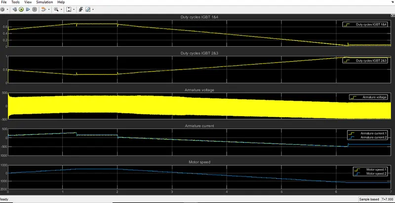
=> Here we run the model we can get the duty cycle IGBT 1&4& duty cycle 2&3 & armature voltage & armature current1 & armature current2 & motor speed1 & motor speed2.
=> So we can say that to control the Aircraft Speed from Zero to Highest the Duty Cycle Range will be from 0 to 87% respectively.
Note:
In this I Didn't Menstion Part- B 6(a) & 6(b) Question Because Of In This EV Live Batch 21 Rasheed Ahmed Told To Us , Please Check.