Week - 4
1 Aim:
- Implement control logic of a “washing machine” using Stateflow as per given sequence:
- If the power supply is available, the system gets activated
- If the Water supply is not available, stop the process & indicate through LED
- Soaking time should be 200s followed by Washing time of 100s.
- Then rinsing happens for next 20s & dryer runs for 50s
Objective:
Washing Machine block diagram.
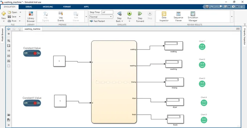
=> In this washing machine input given power supply and water supply here using slider switch.
=> If on slider switch means power and water supply NO.
=> When the hit the run button we got output values like soaking,washing,rinsing,dryer and finish.
=> Here we got output display 0 means incomplected state and 1 means complected state.
=> Here all LED glown as Green means all process has been completed and all display output as 1.
Stateflow chart:
To controlling Washing machine system ON/OFF use slider switch. When the switch is ON all system are and its indicate through Lamp. Then water start enter in machine if the water is not available then sysytem also OFF automatically and indicating through lamp water is available or not available. if available the go on next process soaking, washing, rinsing, drying after all process done end lamp will indicate the process is complete.
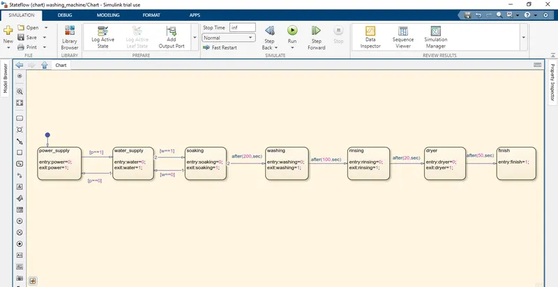
=> In the above control logic first state is created with 2 conditions for power supply.
=> One is with power supply available(PowerSwitch==1)and second with water supply available (W==1).
=> If the power supply at entry is 1 and water supply is on, then machine will get activated and start the next process of operation.
=> Operation states have been created in flow order Soaking,Washing,Rinsing,Drying with their time of operation as 200sec for a soak,100sec for wash,20sec for rinse & 50sec for dry.
=> Entry and exit condition of the state are kept as 0 & at entry of operation states it is 0 and as operation completes it is 1 for every states.
=> After all process has done washing machine completed LED will glow and we can shut the machine off.
Symbol Pane:
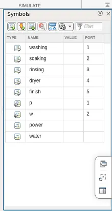
=> In this symbol pane we created Output of power start, water start, soaking, washing, rinsing, drying and input as power switch, water switch for displaying output. they connect to display block.
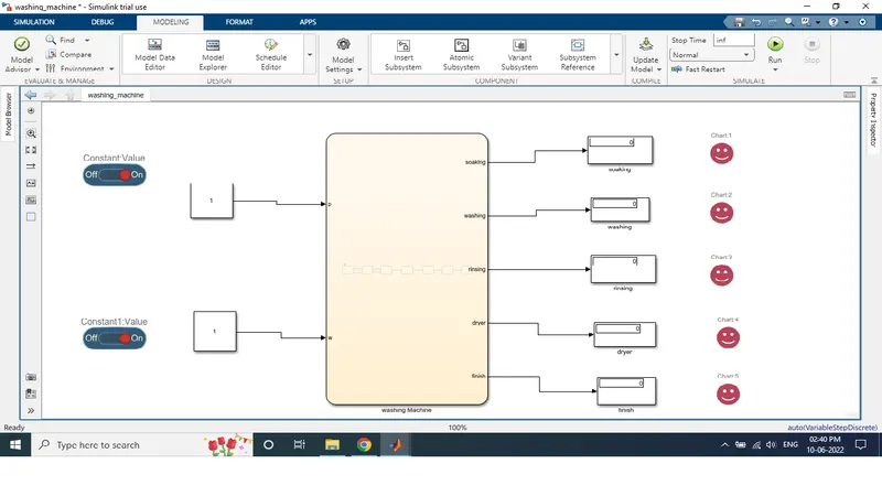
=> Here all LED glown as Red means all process has been incompleted and all display output as 0.
2 Aim:
Make a Simulink chart for the “Gear shift” logic as per below conditions:
Speed Range(kmph) Gear
0 to 15 1
16 to 25 2
26 to 40 3
41 to 60 4
Above 61 5
Give speed input while the simulation is running & display the gear number.
Objective:
Gear shift Block Diagram.
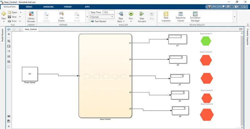
=> In this Gear Shift input given power speed to gear control,so when going speed output gear should be change.
=> In this model we shown when the engine start and the speed is goes to 5kmph then the model shown at that speed the engine is it at 1st gear it is indicated through green lamp.
=> When the hit the run button we got output values like g1,g2,g3,g4,g5 value.
=> Here we got output display 1 means vechile moving with 1st gear and remaining gears are zero positions.
Logic:
=> In this system given speed range is 0-60 so we use power speed for the given input speed.
=> The first gear speed range is 0 to 10 so the entry of state for the 1st gear is 0<=speed and 10>=speed it is the exit condition of gear in speed greater than 10.
=> In gear 2 entry state is 11<=speed and 20<=speed the exit condition is between speed<11 to speed<20. Same conditions are applied in all gears and the output is gives from lamp and dispaly block.
Stateflow Chart:
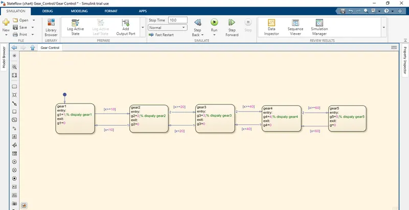
=>The gear transition is decided below
Speed>10 shift to G=2
Speed>20shift to G=3
Speed>40 shift to G=4
Speed>60 shift to G=5
=> when the speed increasing from 0-60kmph simillarly in reverse direction as same. while simulating gear shifting logic engine x==0 condition given to various speed change values.
Symbol pane:
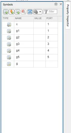
=> In this x is input.
=> In this output as Gear_first, Gear_second, Gear_third, Gear_fourth, Gear_fifith.
Final Model:
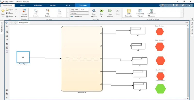
=> In this model the speed of engine is at above 60 then the gear is implemented as 5th and the green light was on and in display block showing figure.