Project 1 (Mini Project on Vehicle Direction Detection
EV Live Batch 21.
1 Aim:
Requirement - 1:
- Steering wheel input as yaw rate (Signal name: SteeringWheel_YawDegreeInput) is the input for this system.
- This is compared against 3 angular values, one each for left turn, right turn & straight drive (Calibration Values: Right_Turn_AngularLimit, Left_Turn_AngularLimit, Straight_Drive_Steering_Angle) to say which specific direction the steering wheel is turning towards.
- Use switch blocks to compare & develop this requirement. Keep this requirement in a subsystem & output of this requirement is a local signal (Signal Name: Vehicle_Turn_Status).
Requirement – 2:
- Keep this requirement as a separate subsystem. Inputs to this requirement are local signal from requirement 1 (Signal Name: Vehicle_Turn_Status) & an input signal from camera (Signal Name: CameraInput_RoadSign), which confirms the occurrence of a road sign.
- Signal Vehicle_Turn_Status is compared against calibration values (Calibration Values: RightTurn_RoadSign, LeftTurn_RoadSign, Straight_RoadSign), if each of them is found equal, then each of the three corresponding output is compared against the camera input signal,
- Using a logical operator block, only one among them is finally given as output signal (Signal Name: Vehicle_Direction_Indicator).
Objective of Mini Project:
- Development of MATLAB Simulink model as per requirement.
- Tag the requirements to the simulink model; tagging requirement 1 & requirement 2 to their corresponding subsystems is fine.
- MBD compliant changes, Data Dictionary creation & code generation is added advantage, and that is not scope of this project.
- If choosing code generation, Storage class for Input signals: ImportedExtern; Storage class for Output signal: Export to File; Storage class for local signals: localizable; Storage class for calibration signals: Const.
- Choose sample time for all signals as 0.01s
Signals & Calibration Data List:
|
Signal / Calibration Name |
Signal Type |
Data Type |
Dimension |
Min |
Max |
Initial Value |
Units |
|
SteeringWheel_YawDegreeInput |
Input |
Int16 |
1 |
-180 |
180 |
- |
Deg |
|
CameraInput_RoadSign |
Input |
Boolean |
1 |
0 |
1 |
- |
- |
|
Vehicle_Turn_Status |
Local |
Int16 |
1 |
-180 |
180 |
- |
Deg |
|
Right_Turn_AngularLimit |
Calibration |
Int16 |
[1 1] |
-180 |
180 |
30 |
Deg |
|
Left_Turn_AngularLimit |
Calibration |
Int16 |
[1 1] |
-180 |
180 |
-120 |
Deg |
|
Straight_Drive_Steering_Angle |
Calibration |
Int16 |
[1 1] |
-180 |
180 |
0 |
Deg |
|
RightTurn_RoadSign |
Calibration |
Int16 |
[1 1] |
-180 |
180 |
30 |
|
|
LeftTurn_RoadSign |
Calibration |
Int16 |
[1 1] |
-180 |
180 |
-120 |
|
|
Straight_RoadSign |
Calibration |
Int16 |
[1 1] |
-180 |
180 |
0 |
|
|
Vehicle_Direction_Indicator |
Output |
Boolean |
1 |
0 |
1 |
- |
- |
Test_Case:
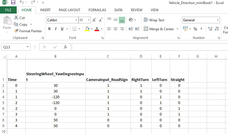
=> First we define this Test_case values to Vehicle_direction.
=> Here I created step wave form 0 to 1 sec soon on I take 4 test cases.
Object:
=> Before we created the SLDD file, Let's we take a Vehicle_direction simulink block, Here we go step wise
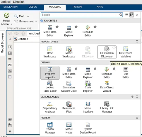
=> Here we take Vehicle_direction simulink block in that go to modeling => link to data dictionary.
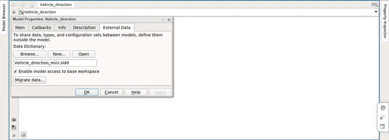
=> When selected the link to data dictionary we got this model properties in this we create the new data dictionary and apply.
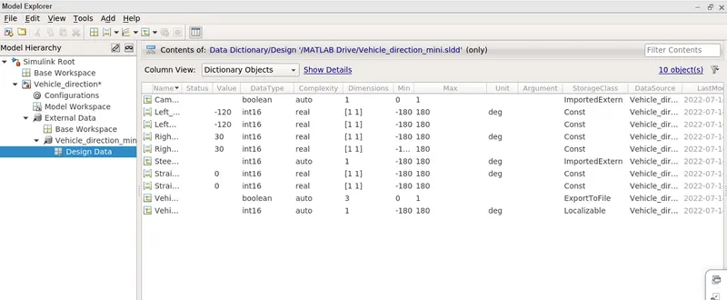
=> When selected applied data dictionary => open Model Explorer, Here we can Design data.
Model Advisor:
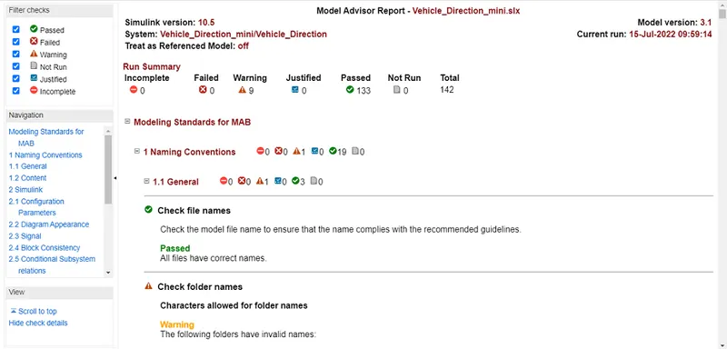
=> Here we checking model in subsystem in By Task.
=> we get report on model advisor.
Simulink Model:
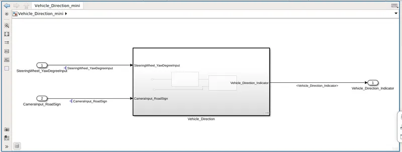
=> Here we created Vehicle_Direction Block connect two input and one output.
=> Here we checking the resolving two input and one output.
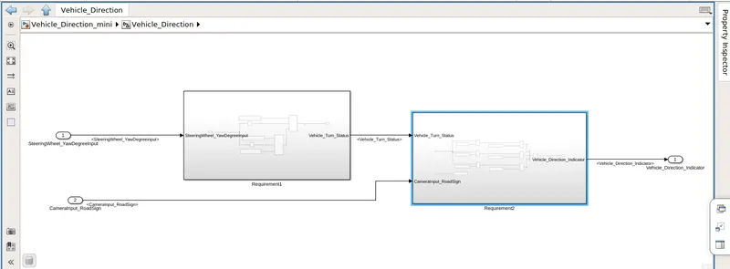
=> In this Vehicle_Direction Block created subsystem, In this subsystem created Requirement 1 and2.
=> Here we connect input and output both.
Vehicle_Direction Block Requirement 1:
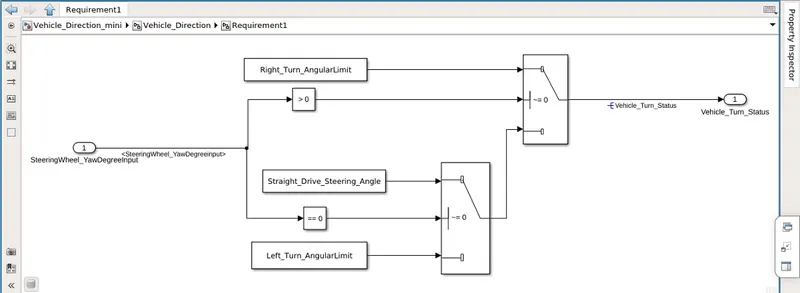
=> Here SteeringWheel_YawDegreeInput comparing 3 angular values Left_Turn, Right_Turn, & Straight_Turn drive.
=> Here range streeing wheel angle is -180 deg to +180 deg
=> Here Right_Turn angle is 30 deg (Turning right positive value)
Left_Turn angle is -120 deg (Turning left negative value)
Straight_Turn angle is 0 deg (means going to stright)
(i) Condition ~=0:
If we give positive value or nagative value the true value will go to the output and we give exactly
Zero in input the false value will go the output.
(ii) Condition >0:
Straight not positive and not negative it's means that going to Left_Turn angularlinit sent to the output.
Vehicle_Direction Block Requirement 2:
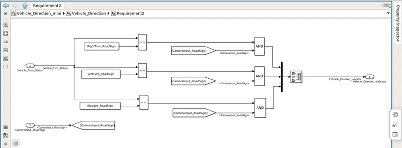
=> This Vehicle_Turn_Status compary with 3 roadsig like: RightTurn_RoadSign
LeftTurn_RoadSign
Straight_RoadSign
=> The RightTurn_RoadSign match (30) then output will be 1
The LeftTurn_RoadSign match (-120) then output will be 1
The Straight_RoadSign match (0) then output will be 1.
=> Here CameraInput_RoadSign is on then only output AND gate will be 1.
Test_Harness_MIL_Case:
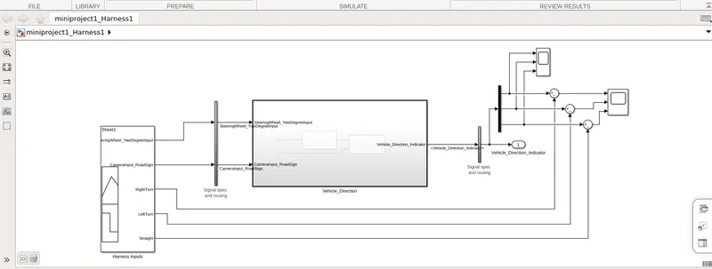
=> Here we create Vehicle_Direction Block Harness and comparying actually output and expected output.
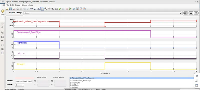
=> Here I Import file Excel sheet from signal builder, so this is the output.
=> What were we given Excel sheet in present signal builder output.
SIL_Test:
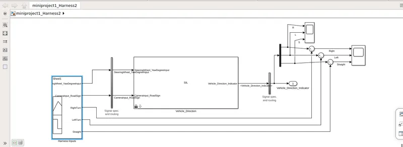
=> In this Vehicle_Direction link with the code folder, when give input it's go to the C code.
=> The output from the C code generated, Here we testing generated code throught the SIL block.
Result:
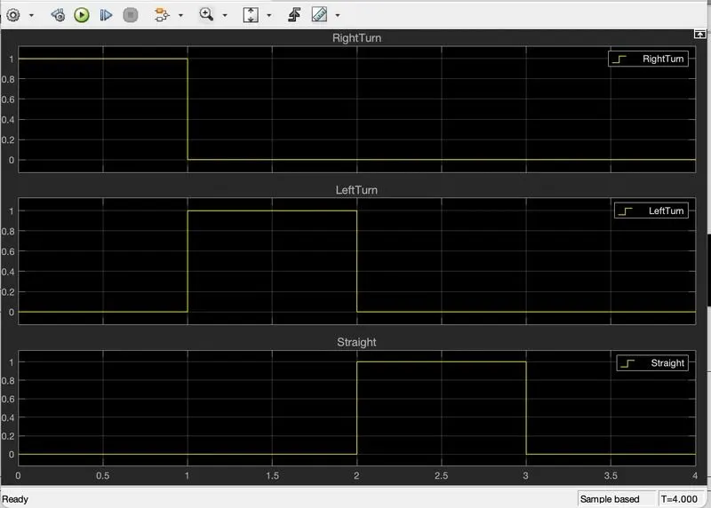
=> This is the actually here 0 to 1 sec it's right actually output is 1,0,0.
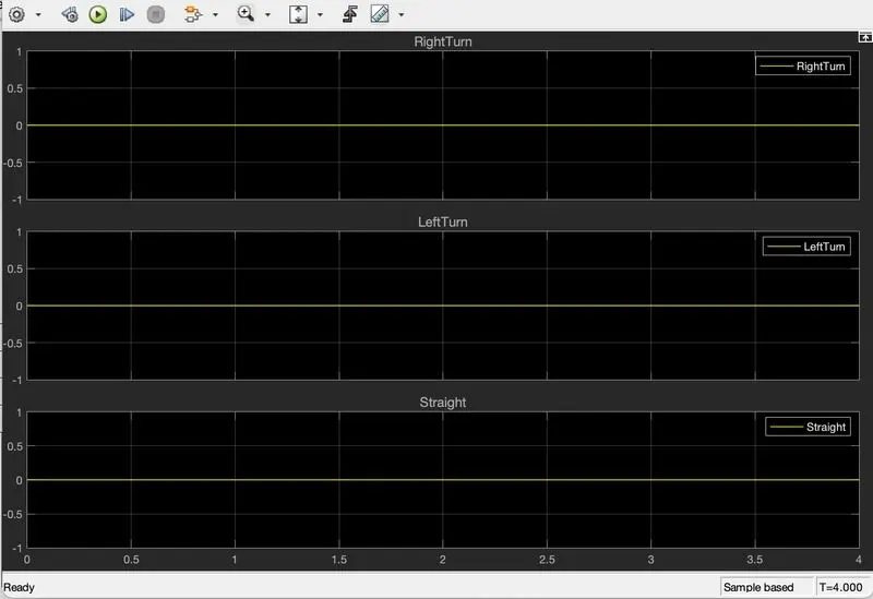
=> This is the expected output wave form constant '0'.