Project-1: Powertrain for aircraft in runways
Part A:
Que-1) Search and list out the total weight of various types of aircrafts.
| Name of the Aircraft | Gross Weight in KG |
| Antanov AN-225 | 6,40,000 |
| Airbus A380-800 | 5,75,000 |
| Boeing 747-800 | 4,47,700 |
| Airbus A340-500 | 3,72,000 |
| Boing 777-300ER | 3,52,000 |
| Boienig 787-10 | 2,54,000 |
| Boeing 737-900 | 85,000 |
| Airbus A320-100 | 68,000 |
| Embraer | 48,000 |
| Gulfstream G650 | 45,200 |
| Bombardier CRJ900 | 36,500 |
| Bombardier Q400 | 28,000 |
| Learjet 75 | 9,700 |
| Cessna Citation CJ4 | 7,800 |
| Beechcraft Bonanza G36 | 1,660 |
| Cessna 206H | 1,660 |
| Sirrus SR22 | 1,630 |
| Cessna 172R | 1,100 |
Que-2) Is there any difference between ground speed and air speed?
The Ground Speed and Air speed are completely different. The Ground Speed referes to the speed of the air craft with respect to the Ground where as Air speed referes to the speed of the aircraft with respect to the air it is flying in.
Ground Speed:
It is the speed of the aircraft relative to the Ground. Ground speed determines how fast an aircraft will get to its destination.
Air Speed:
It is the speed at which an aircraft is moving relative to the air it is flying in. As such, it’s also the speed at which the air is flowing around the aircraft’s wings. Airspeed is what determines whether there is enough airflow around an aircraft to make it fly.
The relationship between airspeed and ground speed is "ground speed is the sum of airspeed and wind speed". If the aircraft is flying in the same direction as the wind is blowing, the aircraft experiences tailwind, and its ground speed is higher than its airspeed. On the other hand, if the wind is blowing against the direction the aircraft is traveling in, the aircraft experiences headwind, and its ground speed is lower than its airspeed.
Let us consider an example. Imagine an aircraft that cruises at an airspeed of 500 miles per hour that has to cover a ground distance of 2,000 miles.
Case-1): If there is no wind at all, then both the aircraft’s airspeed and ground speed would be the same 500 miles per hour, and the aircraft would reach its destination in four hours.
Case-2): If there was a 100 miles per hour headwind – wind blowing against the aircraft’s direction of travel – the aircraft would still be traveling at an airspeed of 500 miles per hour. However, its ground speed would be just 400 miles per hour (100 miles per hour slower than its airspeed). And as such, it would take the aircraft five hours to reach its destinations.
Case-3): Finally, if there was a 100 miles per hour tailwind – wind blowing in the same direction as the aircraft’s travel – the aircraft would still be traveling at an airspeed of 500 miles per hour, but its ground speed would be 100 miles faster. And, at 600 miles an hour, the aircraft would reach its destination in just three hours and twenty minutes.
Que-3) Why is it not recommended to use aircraft engine power to move it on the ground at Airport?
There are different reasons why aircraft engine power to move it on the ground at Airport.
- Aircraft engines can create Hazardous condition. When an aircraft's engine is activated, the thrust can create a high-speed wind that can easily cause damage to the airport terminal, surrounding ground vehicles, jetway, baggage and most importantly, ground personnel.
- As it uses high fuel to move the vehicle, to save the fuel the aircraft engine power to move it on the ground at Airport.
- Many people will work on the ground area, if the engine power is used due to its high power and high speed wind it is dangerus to the people who are working on the ground.
- On the ground many tools, stones and other utilies. Due to high speed of engine it may suck into it. It will damage the engine.
due to these reasons it not recommended to use aircraft engine power to move it on the ground at Airport.
Que-4) How an aircraft is pushed to runway when its ready to take off?
Taxing and Towing methods are used to push the aircraft when it is ready to take off.
Towiing is the method where the aircraft engine power are not used to move as it is dangerous. A tow vehicle like a tractor will help the aircraft to move from the ground. As it reaches the Taxiing position, the tow vehicle is disconnected from aircraft ,now it moves to the take off position on the runway through its own engine power this is known as Taxiing.
Towing: plane moving to assigned spot in airport with towing assistance from a tractor.
Taxiing: plane moving to assigned spot in airport under own power.
Que-5) Learn about take off power, tyre design, rolling resistance, tyre pressure, brake forces when landing.
Take off Power:
The amount of power that an engine is allowed to produce for a limited period of time for takeoff. The use of takeoff power is usually limited to 5 min for reciprocating engines and up to 2½ min for gas turbine engines. This may not always be the case. Specifically, with respect to reciprocating engines, it is the brake horsepower developed under standard, sea-level conditions and under the maximum conditions of the crankshaft rotational speed and the engine manifold pressure approved for the normal take off. It is limited in continuous use to the period of time shown in the approved engine specifications. With respect to gas turbine engines, it is the thrust developed under static conditions at a specified altitude and atmospheric conditions of the rotor shaft rotational speed and gas temperature approved for the normal takeoff. It is limited in continuous use to the period of time shown in the approved engine specifications.
In other words the power used to take the arcraft from ground to sky for requied distance above from the ground (i.e., take off) is known as Take off Power.
Tyre Design:
Unlike an automobile or truck tyre, it does not have to carry a load for a long period of continuous operation. However, an aircraft tyre absorbs the high impact loads of landing, and also it’s operating at high speeds for a short time when required.
Designing aircraft tires is a very intense undertaking. Once an aircraft manufacturer goes to the tire manufacturer with the size and weight requirements, the tire manufacturer begins the process of designing a tire that meets the needs of the aircraft manufacturer as well as all regulatory requirements — including foreign regulations in many cases.
Engineers are challenged with designing tires with cool running, heat-resistant materials while simultaneously exceeding tire service requirements. Tire prototypes are put through rigorous tests that simulate cycles of landings, take-offs, and taxi operations
Two types of tires are used in aircraft applications — bias-ply tires and radial tires. Although both types of tires share some similarities in design, there are differences that need to be noted.
Bias-ply tire construction:
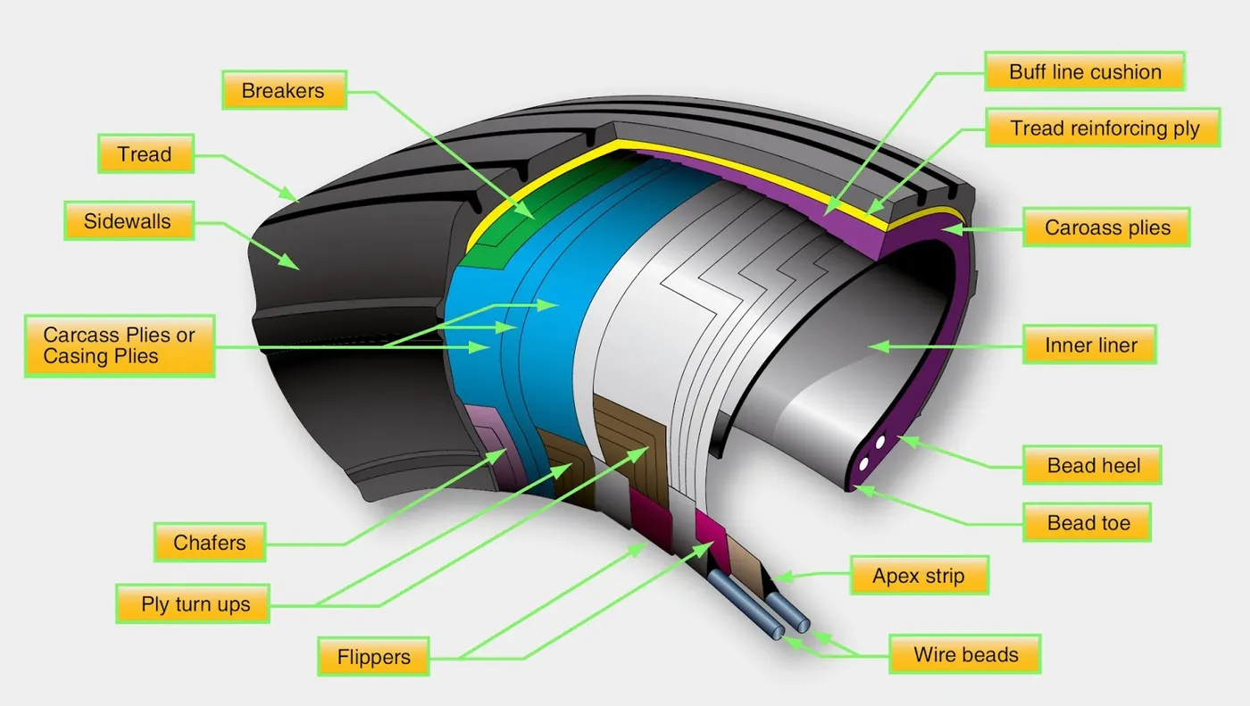
A cutaway of a typical bias-ply tire is shown in Figure 1. Bias-ply tires are popular choices for aircraft tires because of their durability and retreadability. The tire construction consists of the following components:
Tread: The tread is made of rubber mixed with other additives to obtain the desired level of toughness, durability, and resistance to wear. The tread pattern is designed to aircraft operational requirements, with the ribbed tread design used widely due to its good traction under varying runway conditions.
Sidewall: The sidewall is a protective layer of rubber that covers the outer casing ply. It extends from the tread edge to the bead area.
Tread Reinforcing Ply: One or more layers of fabric that strengthens and stabilizes the tread area for high-speed operation. It also serves as a reference for the buffing process when tires are retreaded.
Buff Line Cushion: The buff line cushion is made of rubber compound to enhance the adhesion between the tread reinforcing ply and the breakers or casing plies. It is of sufficient thickness to allow for the removal of the old tread when the tire is retreaded.
Breakers: Breakers are reinforcing plies of rubber-coated fabric placed under the buff line cushion to protect casing plies and strengthen and stabilize the tread area. They are considered an integral part of the casing construction.
Casing Plies: Alternate layers of rubber-coated fabric (running at opposite angles to one another) provide the strength of the tire.
Wire Beads: Hoops of high tensile strength steel wire that anchor the casing plies and provide a firm mounting surface on the wheel. The outer edge of the bead that fits against the wheel flange is called the bead heel. The inner bead edge is called the bead toe.
Apex Strip: A wedge of rubber affixed to the top of the bead bundle.
Flippers: Layers of rubberized fabric that help anchor the bead wires to the casing and improve the durability of the tire.
Ply Turnups: The casing plies are anchored by wrapping them around the wire beads, thus forming the ply turnups.
Chafer: A protective layer of rubber and/or fabric located between the casing plies and wheel to minimize chafing.
Liner: In tubeless tires, the liner is a layer of low permeability rubber that acts as a built-in tube and restricts gas from diffusing into the casing plies. In tube-type tires, a thinner liner is used to prevent tube chafing against the inside ply.
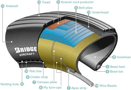
Overlay: A layer of reinforcing rubber coated fabric placed on top of the belts to aid in high speed operation.
Belt Plies: A composite structure that stiffens the tread area for increased landings. The belt plies increase the tire strength in the tread area.
Casing Plies: As in bias-ply tires, the casing plies are layers of rubber-coated fabric. However, unlike those in bias plies that run at opposite angles to one another, radial plies run radially from bead to bead.
Chippers: The chippers are layers of rubber-coated fabric applied at diagonal angles that improve the durability of the tire in the bead area.
Rolling Resistance:
The rolling resistance force is given by
Frr = μrr*m*g
where, Frr = Rolling Resistance force
μrr = rolling resistance coefficient
m = mass of the vehicle
g = Acceleration due to gravity
The coefficient is a function of the tire material,tirw structure,tire temperature,tire inflationpressure,tread geometres,road roughness,road material and the pressure or absence of liquids on thred ect. The value varies with speed ,tire pressure increaeases its value decreases.
Brake forces when landing:
The force required to stop the aircraft to rest postion is calling Braking force. The amout of brake force required depends on the speed and mass of the aircraft.
Braking Power = `1/2*(m*V^2)/t`
where, m = mass in kg
V = velocity of the aircraft in m/s
t = time taken to bring the aircraft to max speed to 0 speed in seconds
Brake force = Braking power/ Velocity
As the aircrafts are huge in mass they requir huge braking force. They are done by the hydrolics ans electric braking.
Part B:
Que-6)
A. With necessary assumptions, calculate the force and power required to push / pull an aircraft by a towing vehicle.
Boing 777-300ER aircraft and assume the following data
total weight of the aircraft = 3,52,000 kg
Curb weight of Towing vehicle = 15200kg
Total weight = 3,67,200 kg
width = 19 m
hegight = 6 m
Area = 19*6 = 114m^2
Rolling resistance constant = μrr = 0.002
acceleration due to gravity = g = 9.8 m/s^2
Air density = ρ = 1.225 kg/m^3
Drag coefficient = Cd = 0.8
Let the speed of the towing vehicle speed = V = 10 Kmph = 2.77778 m/s
Total Tractive force = Rolling resistance force + Drag force + Hill climbing force + Acceleration force
Note that the runway area is flat so hill climing force = 0 and let us consider that towing vehicle is moving at constant speed so the Acceleration force is also = 0
Rolling Resistance force = Frr = μrr*m*g
Frr = 0.002*3,67,200*9.8
Frr = 7197.12N
Drag force = Fad = 1/2*ρ*A*Cd*V^2
`Fad = 1/2*1.225*114*0.8*2.778^2`
Fad = 431.0875 N
Ftr = Frr+Fad
Ftr = 7197.12 + 431.0875
Ftr = 7,628.2075 N
Power = Ftr * V
Power = 7,628.2075*2.778
Power = 21,191.160435w => 21.1 KW
The Force required to push / pull an aircraft by a towing vehicle = 7,628.2 N
The Power required to push / pull an aircraft by a towing vehicle = 21.1 KW
B. Develop the model for the calculated force and power using Simulink.
Developed a model using in simulink using constanta and calculation blocks
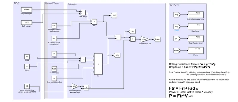
INPUT system conatins the Payload ,Curb weight,Width of aircraft,Height of aircraft,Speed of the towtruck. Theses values are depend on the type of aircraft used to pull.
Constant value system contains all the constant values of Rolling resistance constant,acceleration due to gravity, Air density, Drag coefficient. Which chagens depending on the condition, in general the values are taken as
Rolling resistance constant = μrr = 0.002
acceleration due to gravity = g = 9.8 m/s^2
Air density = ρ = 1.225 kg/m^3
Drag coefficient = Cd = 0.8
Calculation part contains the all the convertions and Calculation are done according to tahe equations
Rolling Resistance force = Frr = μrr*m*g
Drag force = Fad = 1/2*ρ*A*Cd*V^2
Ftr = Frr+Fad
Power = Ftr * V
OUTPUT system contains all the output values need such as
Rolling Resistance force(Frr) in N
Drag force(Fad) in N
Total Tractive force(Ft) in N
Power(P) in KW
Que-7)
A. Design an electric powertrain with type of motor, it’s power rating, and energy requirement to fulfill aircraft towing application in Simulink. Estimate the duty cycle range to control the aircraft speed from zero to highest. Make all required assumptions. Prepare a table of assumed parameters. Draw a block diagram of powertrain.
Let us take the data from the 6th question
Boing 777-300ER aircraft and assume the following data
total weight of the aircraft = 3,52,000 kg
Curb weight of Towing vehicle = 15200kg
Total weight = 3,67,200 kg
width = 19 m
hegight = 6 m
Area = 19*6 = 114m^2
Rolling resistance constant = μrr = 0.002
acceleration due to gravity = g = 9.8 m/s^2
Air density = ρ = 1.225 kg/m^3
Drag coefficient = Cd = 0.8
Let the speed of the towing vehicle speed = V = 10 Kmph = 2.77778 m/s
The Force required to push / pull an aircraft by a towing vehicle = 7,459.43 N
The Power required to push / pull an aircraft by a towing vehicle = 21.1 KW
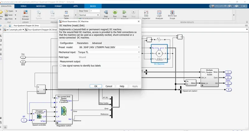
Roughly the power is equal to 30HP
The battery Power i.e., is taken as more than the Motor power. It depends upon how much time we need to run the vechicle.
So, in this case I want to run the Vehicle to 2 hours than the battery capacity should be 2 times of the motor power.
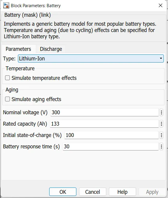
The batter capacity is taken as 40KwH with 300v . Its Amper Hour will be 133Ah
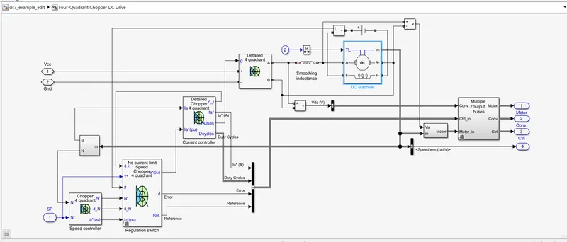
We can model this by taking the DC7 model and make the nesseary changes like battery power and motor power.
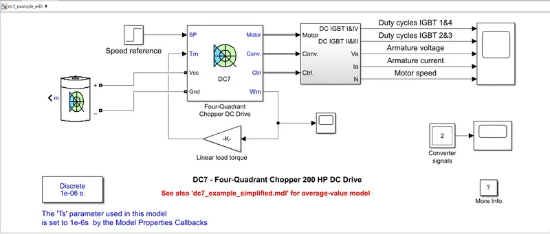
Battery Parameters:
Motor Parameters:
Duty Cycle :
D = output power/input power
D = 21/40 = 52.5%
The duty cycle range to control the aircraft speed from zero to highest is equal to 52.5%
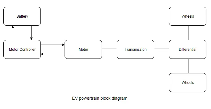
Block Diagram of Power train:
B. Also, Design the parameters in excel sheet.
By taking the parameter in 6th question Excel sheet is created
Rolling Resistance force = Frr = μrr*m*g
Drag force = Fad = 1/2*ρ*A*Cd*V^2
Ftr = Frr+Fad
Power = Ftr * V
Assumptions :
Total run time is 2 hours
Motor with 300V
Battery Voltage with 300V
Battery Capacity = Power*number of hours
Amper hour of battery = KwH*1000/Battery voltage