Project-1: Powertrain for aircraft in runways
OBJECTIVE:
Part A:
- Search and list out the total weight of various types of aircrafts.
- Is there any difference between ground speed and air speed?
- Why is it not recommended to use aircraft engine power to move it on the ground at the Airport?
- How an aircraft is pushed to runway when its ready to take off?
- Learn about take-off power, tyre design, rolling resistance, tyre pressure, brake forces when landing.
Part B:
- A. With necessary assumptions, calculate the force and power required to push / pull an aircraft by a towing vehicle. B.Develop the model for the calculated force and power using Simulink.
- A. Design an electric powertrain with type of motor, it’s power rating, and energy requirement to fulfil aircraft towing application in Simulink. Estimate the duty cycle range to control the aircraft speed from zero to highest. Make all required assumptions. Prepare a table of assumed parameters. Draw a block diagram of powertrain.
(Hint :DC7 Block)
B.Also, Design the parameters in excel sheet.
Answer:
Part-A:
- Search and list out the total weight of various types of aircraft.
Let’s take these weights one by one.
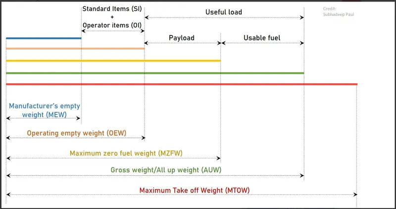
- Manufacturer’s Empty Weight (MEW):It is the weight of the aircraft “as built” and includes the weight of the structure, power plant (engines), furnishings, installations, systems, and other equipment that are considered an integral part of an aircraft.
- Zero Fuel Weight (ZFW): This is the total weight of the airplane and all its contents includingunusable fuel (unusable fuel is the fuel that is required to maintain the structural stability of the aircraft, especially wings), but excluding the total weight of the usable fuel on board (usable fuel is the fuel necessary for the flight). Note: As a flight progresses and fuel is consumed, the total weight of the airplane reduces, but the ZFW remains constant.
- Operational Empty Weight (OEM)or Dry Operating Weight (DOW): It is the basic weight of an aircraft including the crew, all fluids necessary for operation, (such as engine oil, engine coolant, water, unusable fuel) all operator items and equipment required for flight but excluding usable fuel and the payload.
- Maximum Zero Fuel Weight (MZFW):Maximum zero fuel weight (MZFW) is the maximum weight allowed before usable fuel and other specified usable agents (engine injection fluid, and other consumable propulsion agents) are loaded. OR (OEM / DOW + Payload = MZFW)
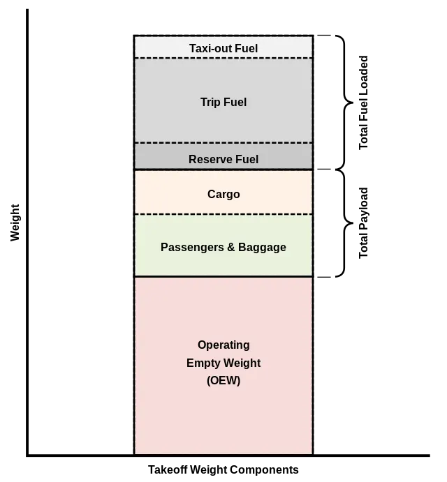
- Maximum Taxi Weight (MTW) or Maximum Ramp Weight (MRW):It is the maximum permitted weight of the aircraft at which it may be moved on the ground either with its own engine or towed by a tractor. It can also be defined as the maximum weight for ground maneuvering including the weight of run-up and taxi fuel. (MZFE + Ramp Fuel = MRW)
- Maximum Take-Off Weight (MTOW):It is the maximum permitted weight at the start of the take-off. While determining this limit, the manufacturer takes into consideration the strength of the material used for the manufacturing of the aircraft and standard performance variables such as runway temperature, altitude, atmospheric pressure, wind components, flaps, etc. (MZFW + Take-Off Fuel = MTOW)
- Regulated Take-Off Weight (RTOW):As told in the above definition depending on different factors (e.g., flap setting, altitude, air temperature, length of the runway), RTOW, or maximum permissible take-off weight varies for each take-off. It can never be higher than MTOW.
- All Up Weight (AUP):DOW + Payload + Fuel.
- Maximum Landing Weight (MLW): When the aircraft touches the ground it puts the force of the runway as well as on the tires and undercarriage, so to ensure the structural safety of the aircraft MLW is taken into consideration. Manufacturers have calculated this force to be approximately “9” times the weight of the aircraft. Thus, when the aircraft has to make an emergency landing or when the weight of the aircraft before landing exceeds the MLW defined by the manufacturer the pilots dump fuel to reduce the weight of the aircraft. (MTOW – Trip Fuel = MLW)
Total weight of various types of aircraft:
|
Type |
MTOW [kg] |
MLW [tonnes] |
|
640,000 |
591.7 |
|
|
589,670 |
||
|
575,000 |
394 |
|
|
447,700 |
346.091 |
|
|
443,613 |
306.175 |
|
|
412,770 |
295.742 |
|
|
Antonov An-124-100M |
405,060 |
330 |
|
396,900 |
295.742 |
|
|
381,000 |
288.417 |
|
|
377,840 |
285.700 |
|
|
377,840 |
260.320 |
|
|
371,950 |
240 |
|
|
367,400 |
256 |
|
|
347,800 |
260.816 |
|
|
351,800 |
251.29 |
|
|
347,450 |
223.168 |
|
|
340,200 |
265.300 |
|
|
308,000 |
233.5 |
|
|
299,370 |
237.683 |
|
|
297,550 |
213.00 |
|
|
276,700 |
190 |
|
|
273,300 |
185 |
|
|
270,000 |
175 |
|
|
270,000 |
195.04 |
|
|
256,280 |
183 |
|
|
254,000 |
192.777 |
|
|
254,000 |
201.849 |
|
|
253,500 |
181 |
|
|
251,000 |
191 |
|
|
250,000 |
175 |
|
|
242,000 |
185 |
|
|
242,000 |
180 |
|
|
231,300 |
166.92 |
|
|
228,000 |
172.365 |
|
|
211,400 |
||
|
208,000 |
175 |
|
|
204,000 |
158.758 |
|
|
192,000 |
140 |
|
|
187,000 |
136.08 |
|
|
185,000 |
111.1 |
|
|
163,000 |
138 |
|
|
159,000 |
136.078 |
|
|
157,000 |
124 |
|
|
152,000 |
151.9 |
|
|
151,000 |
97.5 |
|
|
151,000 |
112.1 |
|
|
147,000 |
||
|
142,000 |
123 |
|
|
141,000 |
122 |
|
|
140,000 |
||
|
125,000 |
||
|
124,000 |
101.6 |
|
|
117,000 |
86.3 |
|
|
116,000 |
89.9 |
|
|
106,000 |
79.5 |
|
|
104,000 |
79.5 |
|
|
104,000 |
80 |
|
|
104,000 |
87.5 |
|
|
87,500 |
||
|
85,000 |
66.36 |
|
|
85,000 |
71.35 |
|
|
84,000 |
70.1 |
|
|
Airbus A321-100[18] |
83,000 |
77.8 |
|
79,000 |
65.32 |
|
|
78,000 |
68.1 |
|
|
73,000 |
63.28 |
|
|
72,500 |
62.4 |
|
|
72,500 |
62.4 |
|
|
71,000 |
64.41 |
|
|
70,700 |
||
|
70,000 |
58.06 |
|
|
Airbus A320-100[18] |
68,000 |
66 |
|
68,000 |
54.9 |
|
|
68,000 |
||
|
67,000 |
||
|
66,000 |
54.66 |
|
|
65,000 |
57.61 |
|
|
65,000 |
||
|
64,000 |
62.5 |
|
|
63,000 |
51.7 |
|
|
60,000 |
49.9 |
|
|
59,000 |
50.80 |
|
|
59,000 |
57.5 |
|
|
55,000 |
47.174 |
|
|
55,000 |
||
|
54,000 |
||
|
50,000 |
46.265 |
|
|
50,000 |
||
|
48,600 |
||
|
48,500 |
||
|
48,000 |
43 |
|
|
46,000 |
||
|
46,000 |
39.95 |
|
|
44,000 |
||
|
42,000 |
36.74 |
|
|
39,000 |
||
|
37,500 |
32.8 |
|
|
36,500 |
33.345 |
|
|
36,000 |
32.8 |
|
|
33,000 |
30.39 |
|
|
33,000 |
||
|
30,400 |
||
|
28,000 |
28.01 |
|
|
23,000 |
21.319 |
|
|
22,800 |
22.35 |
|
|
22,800 |
21.5 |
|
|
22,000 |
19.3 |
|
|
18,600 |
18.3 |
|
|
13,150 |
12.930 |
|
|
11,500 |
11.25 |
|
|
10,890 |
10.570 |
|
|
9,752 |
8.709 |
|
|
8,300 |
7.665 |
|
|
8,150 |
7.65 |
|
|
7,765 |
7.605 |
|
|
7,761 |
7.103 |
|
|
7,000 |
||
|
4,800 |
4.43 |
- Is there any difference between ground speed and airspeed?
Ground speed:
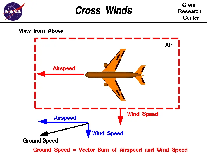
Ground speed is the horizontal speed of an aircraft relative to the Earth’s surface. It is vital for accurate navigation that the pilot has an estimate of the ground speed that will be achieved during each leg of a flight. Ground speed radar can measure it directly.
An aircraft diving vertically would have a ground speed of zero. The information displayed to passengers through the entertainment system of airline aircraft usually gives the aircraft ground speed rather than airspeed.
Ground speed can be determined by the vector sum of the aircraft's true airspeed and the current wind speed and direction; a headwind subtracts from the ground speed, while a tailwind adds to it. Winds at other angles to the heading will have components of either headwind or tailwind as well as a crosswind component.
Airspeed:
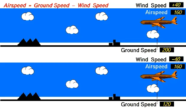
The important quantity in the generation of lift is the relative velocity between the object and the air, which is called the airspeed. Airspeed cannot be directly measured from a ground position but must be computed from the ground speed and the wind speed. Airspeed is the vector difference between the ground speed and the wind speed.
Airspeed = Ground Speed - Wind Speed
On a perfectly still day, the airspeed is equal to the ground speed. But if the wind is blowing in the same direction that the aircraft is moving, the airspeed will be less than the ground speed.
Difference between Ground speed vs Airspeed:
Ground speed is quite different from the airspeed.
Ground speed is easily accurately determinable using GPS.
ground speed is determining how fast an aircraft will get to its destination.
Airspeed determines whether there is enough airflow around an aircraft to make it fly.
Airspeed is more complicated because it can't be directly computed from sensor data, what we get is something called indicated airspeed which is adjusted for instrument error, and produces calibrated airspeed.
If there is no wind then ground speed = airspeed
Gravity is also considered important because the speed of aircraft increases as it is descending.
- Why is it not recommended to use aircraft engine power to move it on the ground at the Airport?
When an aircraft's engine is activated, the thrust can create a high-speed wind that can easily cause damage to the airport terminal, surrounding ground vehicles, jetway, baggage, and most importantly, ground personnel.
Suppressing the use of engines is especially important when towing a large aircraft, as their more powerful thrust capabilities can become exceedingly dangerous. Engine thrust can easily send any loose items airborne, turn the tiniest grains of dust into hazardous projectiles and create debris that can cause damage to multi-million-dollar engines. Additionally, aircraft engines consume a great deal of fuel and generate extreme noise that can be harmful to ground personnel. Using a pushback tug for aircraft is simply a more economical and safer option than running the engines.
Taxiing:
Taxiing (rarely spelled taxying) is the movement of an aircraft on the ground, under its own power, in contrast to towing or pushback where the aircraft is moved by a tug. The aircraft usually moves on wheels, but the term also includes aircraft with skis or floats (for water-based travel).
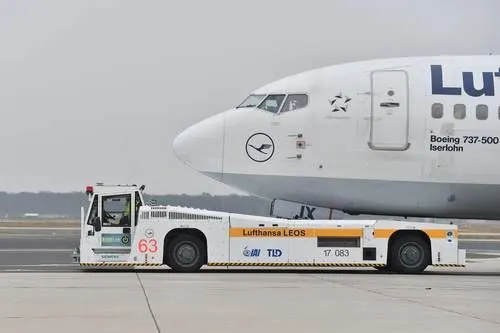
An airplane uses taxiways to taxi from one place in an airport to another; for example, when moving from a hangar to the runway. The term "taxiing" is not used for the accelerating run along a runway prior to take-off, or the decelerating run immediately after landing, which is called the take-off roll and landing rollout, respectively.
The Risk to Operational Safety:
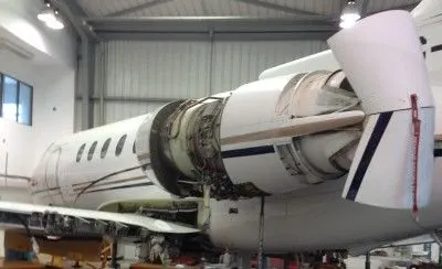
The risks which may arise from engine ground running relate to the potential for loss of control of the aircraft by those persons occupying the pilot seats in the flight deck. In most cases, such persons will be maintenance personnel holding specific company-issued approval for the required tasks. The consequences of loss of control during taxi or towing are the same as apply to these operations generally and this article is concerned only with the risks arising from the static running of one or more aircraft engines. Unwanted consequences from such static running are mainly related to those arising from the unintended movement of the aircraft during engine running - effectively a loss of control - especially during high-power engine running. Damage can occur to the aircraft itself, other aircraft nearby, or to airside structures. In addition, there is a risk of injury to ground support personnel who may be in relatively close proximity to the aircraft.
Overall Risk Mitigation:
The best form of overall mitigation is to ensure that all persons authorized to supervise or directly participate in engine ground running from the flight deck, who are not pilots or flight engineers currently rated on the specific aircraft type, are in receipt of suitable initial training and that there is a proper system for both initial and recurrent qualification for engine ground running duties. Both initial and recurrent qualifications must include practical training and assessment of task competence using either a full flight simulator or an aircraft. Between formal competency assessments, a maximum interval between the performance of the qualified task should be specified. If that interval is exceeded, the qualification would become void until remedial action has been completed. In this respect, the task of engine ground running should be seen as part of a broader group of aircraft ground movement tasks that can be carried out under the control of flight deck occupants other than type-rated flight crew.
Finally, engine ground running, especially if engine operation above Ground Idle is to take place, is best carried out with both flight deck pilot seats occupied and with clearly defined roles for the person in charge and their assistant. In particular, this allows checklists to be carried out using the challenge and response method.
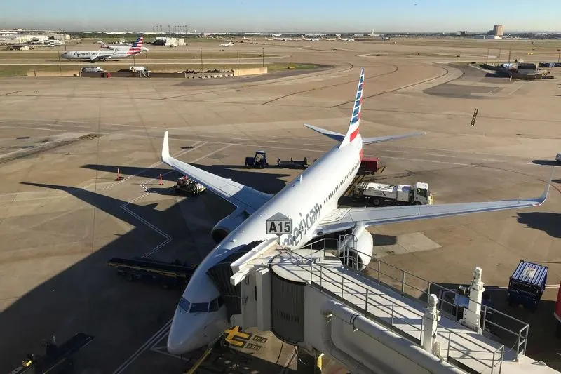
High engine thrust during maintenance activity can cause considerable damage to airplanes and other elements in the airport environment.
For moving on the ground, the aircraft uses its own engine power called taxing.
Many aircraft are capable of moving backward using reverse thrust as a result the jet blast or prop wash might cause damage to the terminal building or equipment.
Engine close to the ground may blow sand or debris.
There is a risk of injury for the people who may be standing close to the aircraft.
To save fuel it is not recommended to use an aircraft engine to move it at the airport.
To avoid noise pollution for the passengers it is not recommended to use aircraft to move in the airport.
- How an aircraft is pushed to the runway when it's ready to take off?
In aviation, pushback is an airport procedure during which an aircraft is pushed backward away from its parking position, usually at an airport gate by an external power. Pushbacks are carried out by special, low-profile vehicles called pushback tractors or tugs.
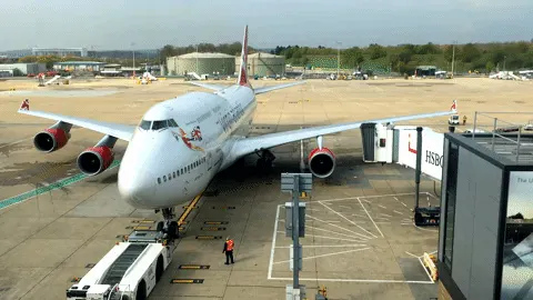
Pushbacks at busy aerodromes are usually subject to ground control clearance to facilitate ground movement on taxiways. Once clearance is obtained, the pilot will communicate with the tractor driver (or a ground handler walking alongside the aircraft in some cases) to start the pushback. Very small airplanes may be moved by human power alone. The airplane may be pushed or pulled by landing gear or wing struts since they're known to be strong enough to drag the airplane through the air. To allow for turns, a person may either pick up or push down on the tail to raise either the nose wheel or tail wheel off the ground, then rotate the airplane by hand.
Large aircraft cannot be moved by hand and must have a tractor or tug. Pushback tractors use a low-profile design to fit under the aircraft's nose. For sufficient traction, the tractor must be heavy, and most models can have extra ballast added. A typical tractor for large aircraft weighs up to 54 tonnes (59.5 short tons; 53.1 long tons; 119,000 pounds) and has a drawbar pull of 334 kN (75,000 lbs). Often the driver's cabin can be raised for increased visibility when reversing and lowered to fit under the aircraft. There are two types of pushback tractors: conventional and towbar less (TBL).
Once the aircraft commander another person is in charge on the flight deck if the aircraft is not in service) has given their confirmation of ‘brakes released’ to the person in charge of the ground crew who are to carry out the pushback, the ground crew become temporarily responsible for the safe maneuvering of the aircraft in accordance with either promulgated standard procedures or as specifically agreed beforehand.
Unless the maneuver is taking place outside the movement area controlled by ATC, an RTF clearance to carry it out will be required. Usually but not always, this will be obtained by the aircraft commander or other person in charge of the flight deck. The prescribed RTF phraseology for pushback is contained in ICAO PANS-ATM.
Formerly, almost all aircraft types required that the ground locking pin be installed in the nose landing gear during any pushback; however, this is now no longer always the case. If a ground locking pin is installed for the pushback, it will need to be removed after the completion of the ground vehicle maneuver if the aircraft has been pushed back prior to the intended flight.
The ‘traditional’ method of allowing the ground vehicle to move an aircraft is to attach it to the aircraft's nose landing gear by means of a towbar. These must be approved for use with a particular aircraft type and clearly marked as such since there is no universal towbar specification. The same towbar attachment and the ground vehicle may also be used for Aircraft Towing in the forward direction. An alternative method that is becoming more common for pushback is the use of a specialized vehicle called a ‘towbar less tug’. This positions two low-level ‘arms’ on either side of the aircraft's nose landing gear and these are used to engage with the aircraft gear leg and raise it slightly off the ground. These specialized vehicles can also be used to tow aircraft forward,
Both pushback methods are subject to the observance of any aircraft limits for maximum nose landing gear steering angle, but these are not usually especially restrictive.
5 TYPES OF AIRCRAFT TUGS:
1. START SMALL – TUGS FOR MOVING LIGHT AIRCRAFT
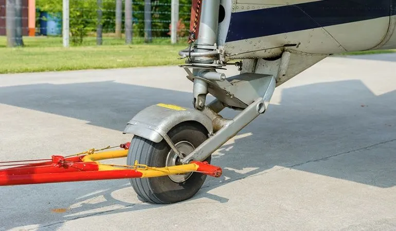
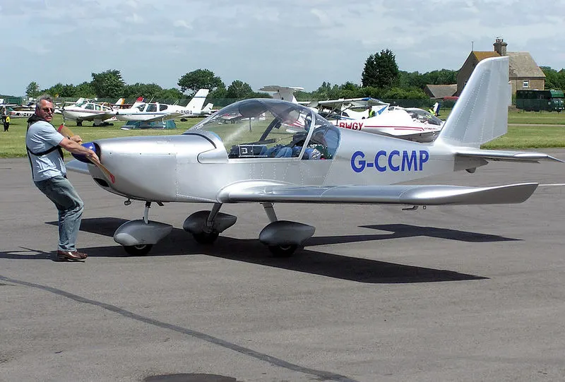
- The common tow bar – A helping hand
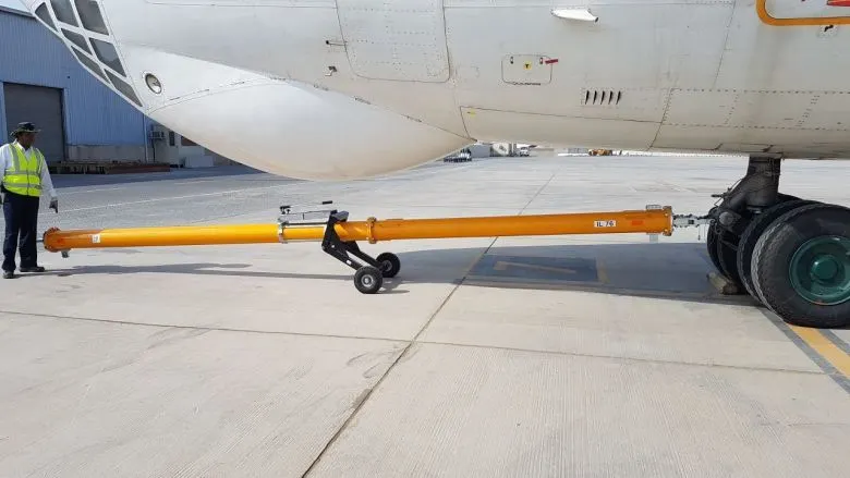
3. Engine-powered conventional tow bar tractors and tugs
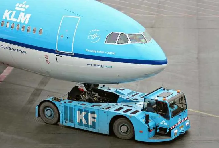
4. Engine-powered towbar fewer tugs
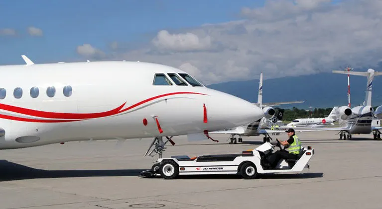
5. Electric towbar less remote–controlled aircraft tugs (mototok).
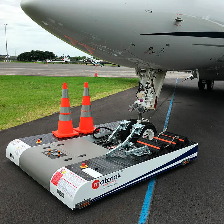
- Learn about take-off power, tire design, rolling resistance, tire pressure, and brake forces when landing.
TAKE-OFF POWER:
Take-off is the phase of flight in which an aircraft goes through a transition from moving along the ground (taxiing) to flying in the air, usually starting on a runway. Usually, the engines are run at full power during take-off. Following the taxi motion, the aircraft stops at the starting line of the runway. Before take-off, the engines, particularly piston engines, are routinely run up at high power to check for engine-related problems. This makes a considerable noise. When the pilot releases the brakes, the aircraft starts accelerating rapidly until the necessary speed for take-off is achieved.
The take-off speed required varies with air density, aircraft weight, and aircraft configuration (flap and/or slat position, as applicable). Air density is affected by factors such as field elevation and air temperature.
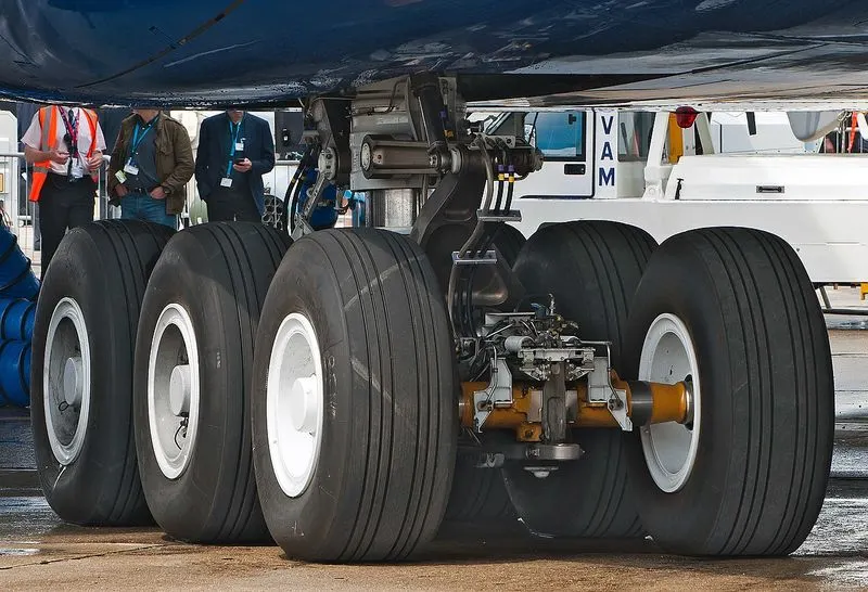
The amount of power that an engine is allowed to produce for a limited period of time for takeoff. The use of takeoff power is usually limited to 5 min for reciprocating engines and up to 2½ min for gas turbine engines. This may not always be the case. Specifically, with respect to reciprocating engines, it is the brake horsepower developed under standard, sea-level conditions and under the maximum conditions of the crankshaft rotational speed and the engine manifold pressure approved for the normal takeoff. It is limited in continuous use to the period of time shown in the approved engine specifications. With respect to gas turbine engines, it is the thrust developed under static conditions at a specified altitude and atmospheric conditions of the rotor shaft rotational speed and gas temperature approved for the normal takeoff. It is limited in continuous use to the period of time shown in the approved engine specifications.
TYRE DESIGN:
An aircraft tire is designed to withstand extremely heavy loads while landing, taking off, taxing, and parking. The number of wheels required for aircraft increases with the weight of the aircraft, as the weight of the airplane needs to be distributed more evenly.
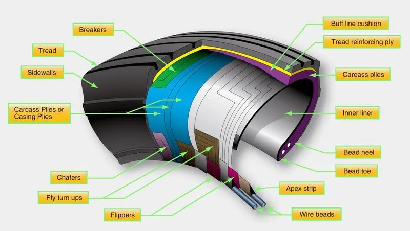
The aircraft tire is a combined structure of these basic materials:
- Rubber
- Nylon
- Cord
- Steel
These tires are combined together by a vulcanization process. The vulcanization process is a chemical process for converting polymers into more durable materials by introducing crosslinks. This process of treating crude or synthetic rubber or similar plastic material chemically to give it useful properties (such as elasticity, strength, and stability)
There are mainly two types of tires: - Radial and Bias, each type has unique components reflecting different technologies applied to design, compounds and materials. To understand the difference between these two different types of tires, you have to first understand the meaning of ply rating. Ply rating is a rating of how many layers of rubber is on a tire. The number of layers of rubber and the angles at which they are laid dictate the strength and load capacity of the tire.
Bias-Ply Tyre:
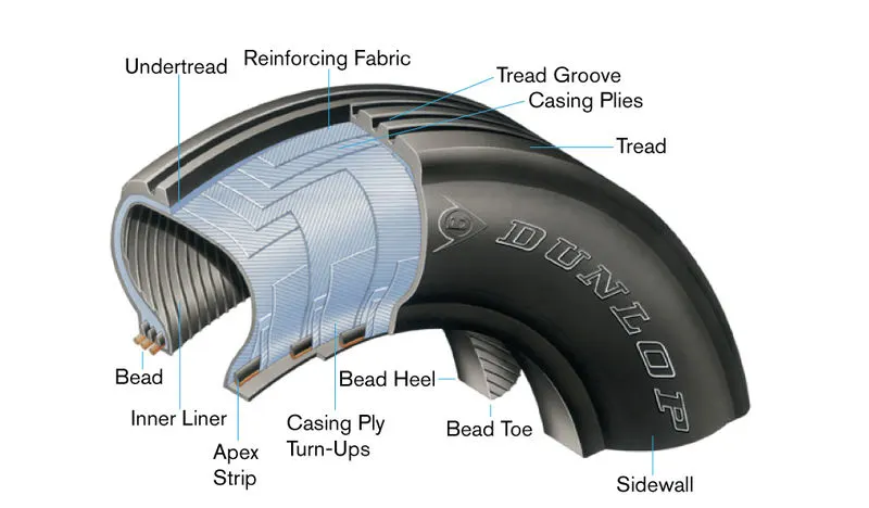
The bias ply tire consists of layers of rubber running diagonally at approximately right angles to one another The bias tire are currently at maximum because of their strength. ITF (Inter Tread Reinforcing Fabric) is used in a bias tire. It provides additional high-speed stability, reduces tread distortion under load, protects the casing plies from damage and can act as wear indicators on re-manufactured tires.
Radial Ply Tyre:
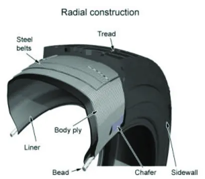
In aircraft with radial ply tires, tires have layers of the tire running radially at an approximate perpendicular to the centre line of the tire. Radial ply tires are low in weight as compared to the bias ply tire but have less strength.
Different Components of Tire:
Tread:
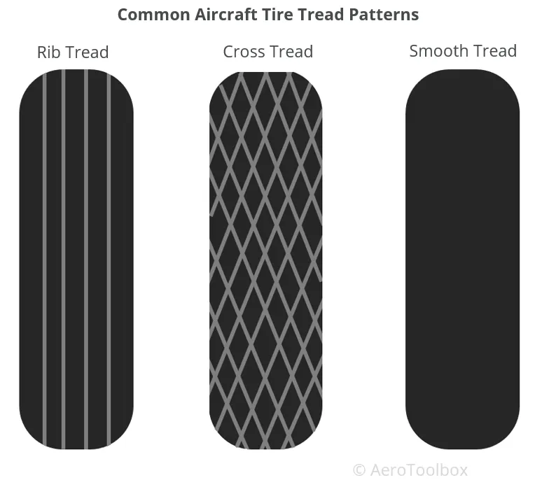
It is a special composite rubber formulated to resist wear and tear, cutting, chunking, and heat build-up. Circumferential grooves are molded into the tread to disperse water from beneath the tread in wet runway conditions. The tread also helps to reduce the risk of aqua planning and improves traction and grip between the tread and runway surface.
Shoulder
The tire shoulder is the portion of the tread between the tread center and the tire sidewall. The tire shoulder offers support and protection to both the sidewall and the tread. The shoulder is a thick part of the tire, enabling the tire to more easily hold its form during cornering maneuvers.
Casing
The foundation strength of the tire is provided by the casing plies. Casing plies are layers of fabric coated with the high modulus of elasticity rubber on both sides to improve its elastic strength. Casing plies are wrapped around the beads (Bead is a wire used for attaching two things very strongly) for proper fitting.
Beads
The bead wire attaches the tire to the rim and ensures an airtight seal. Bead consist of bundles of high-tensile steel wires, each strand of which is coated in rubber compound and wound into coils of the correct diameter for given tire size.
Chafers
Chafers are made of tough nylon material and are fitted around the bead clinch area to resist chafing damage (It is damage caused to the skin of tire due to repetitive rubbing) to both tire and rim flange.
Sidewall
The sidewall is the area of the tire between the shoulder and the bead. The sidewalls of the tire are covered with a layer of specially formulated rubber treated with anti-oxidants. The sidewall of the tire protects the casing from the effects of weathering and offers resistance to cuts and flexing.
Inner tread
Tubeless tires have a layer of rubber bonded to the inside of the first casing ply from bead to bead to resist the permeation of nitrogen and moisture into the casing.
Under tread
The under tread is a layer of rubber that is designed to improve the adhesion between the tread and the casing plies.
Rolling Resistance:
The rolling resistance is primarily due to the hysteresis losses in the vehicle tyres. Friction in bearings and the gearing system also play their part. The rolling resistance is approximately constant and hardly depends on vehicle speed. It is proportional to vehicle weight.
,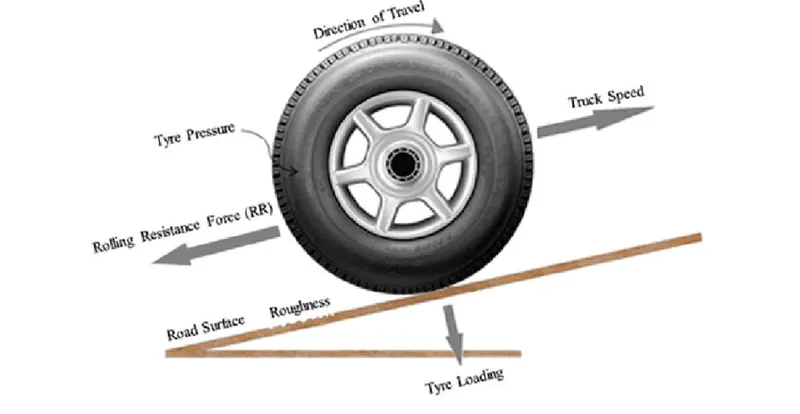
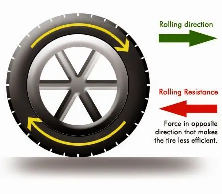
When taking off from a runway covered with slush, standing water or snow, the required take-offground run distance will be longer than on a dry runway. This is the result of the fact that slush, standing water, and snow on the runway will generate a rolling resistance that increases the total resistance of the aircraft during the ground run. Rolling resistance is the combination of forces that work against the forward motion of an aircraft. The weight of the aircraft, gravity and inertia, the amount of friction between the tyres and the road surface, and air drag all play a part.
The most significant factors to be considered are:
Load, Wheel diameter, Tread material/hardness, Floor material/finish, Floor conditions (roughness, cleanliness, slope, etc.).
Frr = μrrmg
where μrr is the coefficient of rolling resistance. The main factors controlling μrr are the type of tyre and the tyre pressure. Any cyclist will know this very well – the freewheeling performance of a bicycle becomes much better if the tyres are pumped up to high pressure, though the ride may be less comfortable.
Tyre pressure:
An aircraft tire or tyre is designed to withstand extremely heavy loads for short durations. The number of tires required for aircraft increases with the weight of the aircraft, as the weight of the airplane needs to be distributed more evenly. Aircraft tire tread patterns are designed to facilitate stability in high crosswind conditions, to channel water away to prevent hydroplaning, and for braking effect.
Aircraft tires also include fusible plugs (which are assembled on the inside of the wheels), designed to melt at a certain temperature. Tires often overheat if maximum braking is applied during an aborted take-off or an emergency landing. The fuses provide a safer failure mode that prevents tire explosions by deflating in a controlled manner, thus minimizing damage to aircraft and objects in the surrounding environment.
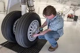
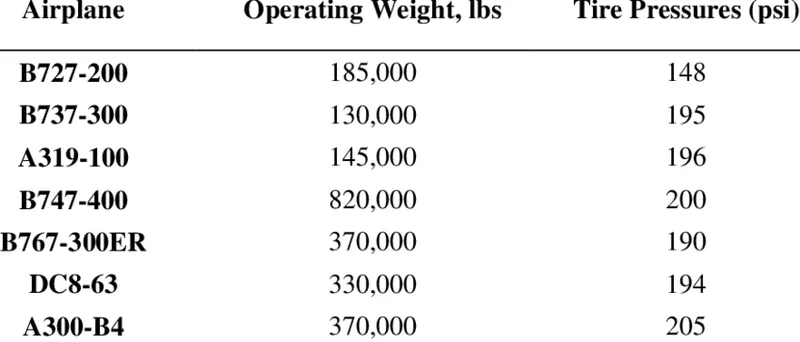
Different aircraft and their pressure values.
Aircraft tires are usually inflated with nitrogen to minimize expansion and contraction from extreme changes in ambient temperature and pressure experienced during flight. Dry nitrogen expands at the same rate as other dry atmospheric gases (normal air is about 80% nitrogen), but common compressed air sources may contain moisture, which increases the expansion rate with temperature.
The requirement that an inert gas, such as nitrogen, be used instead of air for inflation of tires on certain transport category airplanes was prompted by at least three cases in which the oxygen in air-filled tires had combined with volatile gases given off by a severely overheated tire and exploded upon reaching autoignition temperature. The use of an inert gas for tire inflation eliminates the possibility of tire explosion.
BRAKE FORCES WHEN LANDING:
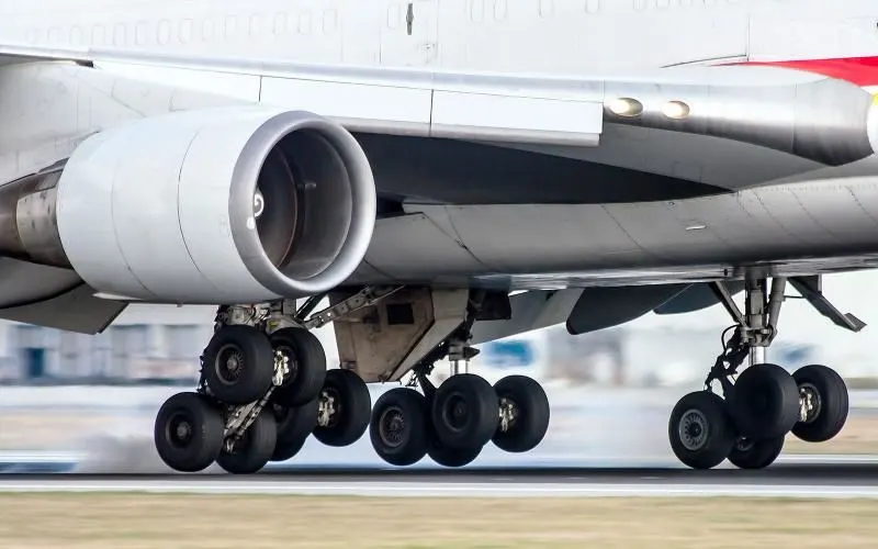
Brakes are responsible for the conversion of excess kinetic energy into thermal energy by increasthe friction. Increasing the amount of friction (i.e., is the resistance offeredthe to motion of a vehicle) reduces the speed of motion of the vehicle. Braking systems employ this principle for slowing down or stopping the vehicles. Braking systems in aircraft are of three basic types: mechanical, hydraulic and pneumatic brakes. Mechanical brakes are those which are operated by the use of linkages, levers cams etc. Hydraulic brakes make use of fluid pressure for transmission of pressure to the braking components while Pneumatic brakes use air pressure for transmitting brake power. These systems either increase the surrounding air drag with the help of airbrakes, spoilers, flaps, reverse thrusters, drag chutes, etc or increase the ground drag using anchors, skids etc for effective braking.
Spoilers:
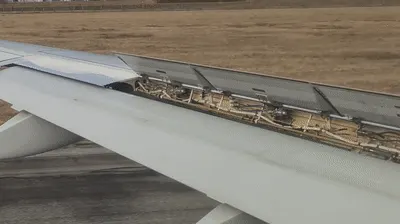
Spoilers are devices used to destroy the lift of an aircraft. These are flap like structure of rectangular cross-section whose leading edge is hinged to the wings (at an angle) disturbing the streamlined f low of air thereby changing the amount of lift. The net force on aeroplane in the vertical direction is equal to weight minus lift. Thus, when the spoilers are employed, lift gets reduced as a result the net downward force acting on the body increases. Spoilers are of two types: flight spoilers and ground spoilers. Fig. 2: Spoiler Hinged on Wings Flight spoilers are used to reduce lift, without increasing speed to a very high rate. This allows easier descent of the aircraft. Ground spoilers also known as lift dumpers are deployed on landing. They slow down the vehicle by increasing the drag and also decrease the lift dramatically. As a result, weight of the aircraft is transferred from the wings to the undercarriage. This leads to ease of braking and also reduces chances of skidding.
Thrust Reversers:
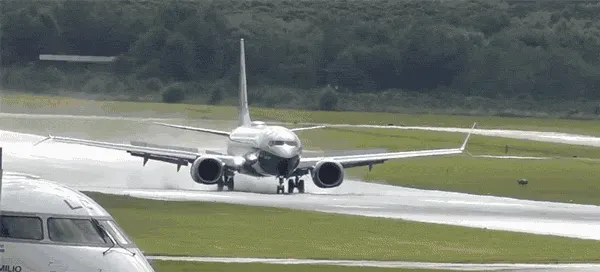
In addition to the normal brakes, thrust reversers are employed for decelerating the aircraft after touchdown especially when the runways are snow covered or icy. Thrust reversers work on the principle of reversal of the direction of the exhaust gases or changing the propeller pitch in order to create a drag force to oppose the motion of aeroplane. Thrust reversal is mainly used to reduce the stopping distance. It enables landing on smaller runways, reduction in the wheel brake wear and taxi distance. It is also used in case of Rejected take offs. In case of wet or icy runways layer of water acts like a lubricating film between the wheel surface and the runway (Hydroplaning). As a result of this, friction reduces. Deployment of thrust reversers which are independent of the surface friction enables better braking in such conditions Since reverse thrust is most effective at high speed, it is important both to initiate reverse early in the landing roll and to increase thrust promptly to the limits recommended for the specific airplane model. Thrust reversers need to be operated just after touchdown and they have a minimum speed requirement below which there is a danger of reinjection of exhaust gases into the engine. Generally, thrust reversers are retracted below a speed of 70mph. In propeller aircraft thrust reversal is accomplished by changing the blade angle of the propeller to produce drag. It involves the use of a hydro mechanical system for actuation in order to slow the aircraft. In turbojet and turbofan aircrafts thrust reversal is achieved by redirecting the air flow of the exhaust gases from the engine. Because of aerodynamic restrictions, the discharge angle is kept 45 degree and as a result, the drag produced for both these systems is 40-60% of the forward thrust.
Disc Brake:
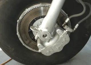
Aircraft typically use disc and multi-disc brakes. It mainly consists of rotating disc attached to the wheel assembly, brake callipers which are held stationary and contains the brake pads made of material such as asbestos, ceramics, carbon etc. When brake pedal is pressed, brake fluid under pressure flows from master cylinder to the slave cylinder via tubes. The slave cylinder consists of piston which gets actuated by the force of incoming fluid pressure. The piston forces the brake pads against the rotating disc. The friction between the brake pad and disc surface, resist its rotating motion and stops it. Disc brakes used these days are differential type i.e., the left and right unit are independent of one another. This also provides increased manoeuvrability. Multiple disc brakes consist of series of discs, the steel stators which is a stationary unit is keyed to the bearing carrier and the rotors form the rotating part and are keyed to the wheel. Automatic adjuster is used for providing clearance between the rotor and stator layers. Under the action of hydraulic pressure, these series of disc get compressed, forcing the wheel to slow down due to friction. These days the discs are provided with slots for better heat dissipation at high temperature. Also, Carbon fibre is being extensively used as rotor material for the brakes because of its low weight and the ability to withstand high heat and temperature. Although it requires lesser maintenance than the conventional brakes but the cost of manufacturing is comparatively high.
PART-B:
6. A.With necessary assumptions, calculate the force and power required to push / pull an aircraft by a towing vehicle.
Solution:
In this challenge we are calculating the force and power required to push/pull an aircraft by a towing vehicle.
For this calculations Airbus318 and Towing vehicle TBL280 s specifications are taken.
Airbus A318 Specifications:
Mass (M) = 59000kg
Height = 12.56m
Width = 39.82m
Frontal area (A) = Height x Width
= 12.56 x 39.82
= 500.1392
= 500.14m^2
Drag Coefficient Cd = 0.0235
Air Density = 1.225 kg/m^3
Towing vehicle TBL280 Specifications:
Mass = 35000 kg
Height = 2m
Width = 3.4m
Frontal Area (A) = Height x Width
= 2 x 3.4
= 6.8m^2
Tyre size = 22” = 0.5588m
Drag Coefficient Cd = 0.6
Air Density = 1.225 kg/m^2
Speed (V) = 32 mph
= 32 x (5/18)
= 8.89 m/s
Total tractive force (Ft) = Air drag force (Fad) + Rolling Resistance (Frr)
Ft = Fad + Frr
Air Drag force Fad = ½ x x A x Cd x V^2
`Rolling Resistance Frr = μrr x m x g`
`Coefficient of Rolling Resistance μrr=0.02`
Airbus Force Calculating:
`Rolling Resistance Frr1 = μrr x m x g`
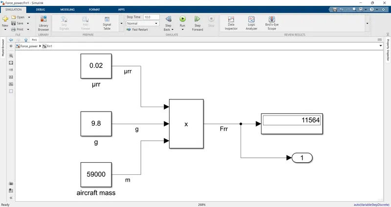
Frr1 = 0.02 x 59000 x 9.8
= 11564 N
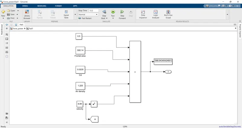
Air Drag force Fad1 = ½ x x A x Cd x V^2
= ½ x 1.225 x 500.14 x 0.0235 x 8.89^2
= 568.94 N
Tow vehicle force calculation:
Rolling Resistance Frr2 =
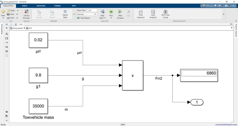
Frr2 = 0.02 x 35000 x 9.8
= 6860 N
Air Drag force Fad2 = ½ x x A x Cd x V^2
= ½ x 1.225 x 6.8 x 0.6 x 8.89^2
= 197.5 N
Total Rolling Resistance force Frr = Frr1 + Frr2
= 11564 + 6860
= 18424
Total Air Drag Force Fad = Fad1 + Fad2
= 568.94 + 197.5
= 766.44
Total Tractive force Ft = Frr + Fad
= 18424 + 766.44
= 19190.44N
Total Tractive power = Tractive force x Velocity
= 19190.44 x 8.89
= 170603.01N
= 170.6 kW
The total Tractive force required to push/pull the aircraft by a towing vehicle = 19190.44N
The total power required to push/pull an aircraft by a towing vehicle = 170.6kW
B. Develop the model for the calculated force and power using Simulink.
In this challenge a Simulink model is developed based on the above Force and Power calculations.
In this simulation Firstly Subsystems are created for Rolling Resistance, Airdrag forces for Aircraft and Towing Vehicles.
Constant, Mathematical operator blocks, Display, go to and from tags blocks are used to develop the model.
The developed model is shown in the below figure.
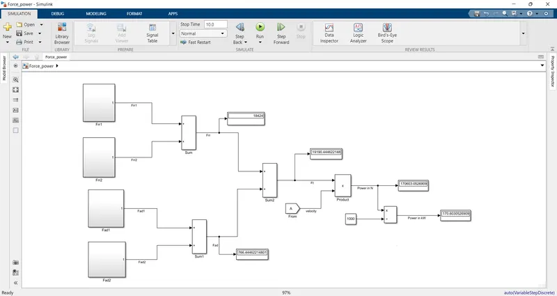
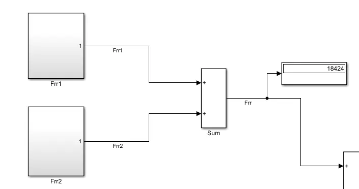
In the above figure, the Rolling Resistance force Frr1 and Frr2 subsystems are created.
aircraft rolling resistance Frr1 subsystem contains Coefficient of Rolling Resistance, the mass of the vehicle and gravitational force is calculated by using mathematical operator block.
for towing vehicle rolling resistance Frr2 calculation is similar to Frr1. mass of the vehicle is changed and remain parameters are same.
The Frr1 subsystem is shown below.
The Frr2 subsystem is shown below.
Air Drag force Fad1 subsystem is shown below.
Air Drag force Fad2 subsystem is shown below.
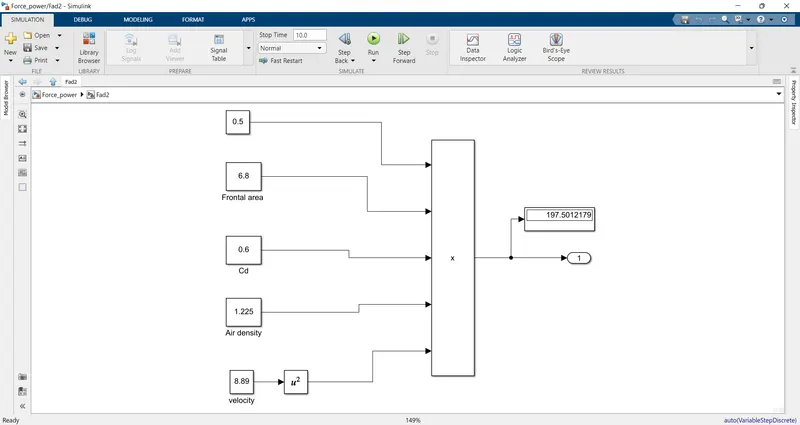
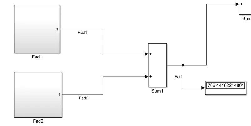
the above figures are representing the air drag force calculations.
Here we are using the constant blocks and multiplication blocks for calculations.
The total rolling resistance force is the sum of aircraft and towing vehicles' rolling resistance forces.
The total rolling resistance fore is shown below.
The total airdrag force Fad is shown below fig.
Total Tractive force Ft, Total power in kW is shown below.
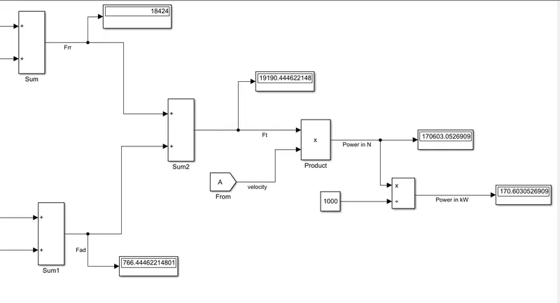
Power is calculated in N, we divide by 1000 to convert the power into Kilo Watts.
The total power in kw is 170.6 kW.
7.A. Design an electric powertrain with type of motor, it’s power rating, and energy requirement to fulfill aircraft towing application in Simulink. Estimate the duty cycle range to control the aircraft speed from zero to highest. Make all required assumptions. Prepare a table of assumed parameters. Draw a block diagram of the powertrain.
(Hint :DC7 Block)
In this challenge we are calculating the energy required to push /pull the aircraft by towing vehicle.
The towing duration taken as 20 minutes, when it is converted into hours 0.33h.
Power = 170.6kW
Energy = power x time
= 170.6 x 0.33
= 56.3 kWh
The energy required for the above-calculated power for 20 minutes is 56.3kWh.
Now we are calculating the Input power for drive the duty cycle of the towing vehicle.
Duty cycle = Output power/Input power
Input power is calculated based on the assumptions of the motor specifications.
Input voltage = 600V
Input current = 400A
Input power = Input voltage x input current
= 600 x 400
= 240 kW.
Duty cycle = output power/input power
= 170.6/240
= 0.7108
= 71.08%
The duty cycle required towing vehicle is 71.08%
Assumed parameters of the vehicles is shown:
Parameter: values:
Aircraft:
Mass = 59000kg
Height = 12.56m
Width = 39.82m
Frontal area = 500.14m^2
Drag coefficient, Cd = 0.0235
Air density = 1.225 kg/m^3
Coefficient of Rolling Resistance 0.02
Gravity g = 9.8 m/s^2
Speed V = 8.89 m/s
Towing vehicle specifications:
Mass = 35000 kg
Height = 2m
Width = 3.4 m
Frontal area = 6.8 m^2
Drag coefficient Cd= 0.6
Air density = 1.225 kg/m^3
Coefficient of Rolling Resistance 0.02
Gravity g = 9.8 m/s^2
Speed V = 8.89 m/s
Tyre size = 0.5588 m
Power train Block diagram:
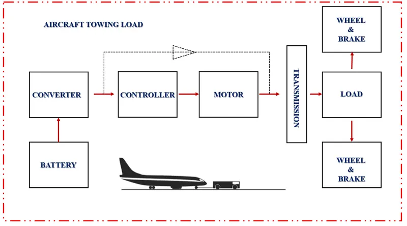
In the above figure, Battery is the power source for the powertrain.
When the battery is supply given to converter unit, it converts the DC supply into Required Output voltage. Then it is given to the controller unit and the controller unit is controls the motor. The output of the motor is given to the transmission system. The transmission system is connected to load, wheels and brake.
We have to design an electric powertrain with type of motor, its power rating an energy requirement to fulfil aircraft towing applications in Simulink.
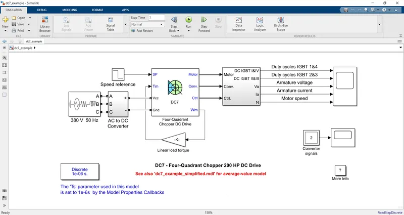
In this model 3 phase 380V, 50HZ AC supply is taken as input supply. Then it is fed into AC to DC converter, in this converter AC supply converted into Required DC supply. Output of the Converter unit is given as input to the DC7 Chopper block. The speed reference, angular speed is taken as fed back signal and multiplied by gain and given to DC7 chopper block. From the selector block output are taken as Armature Voltage, Armature Current, Motor Speed, Duty Cycles of IGBT 1 to 4 are given to scope.
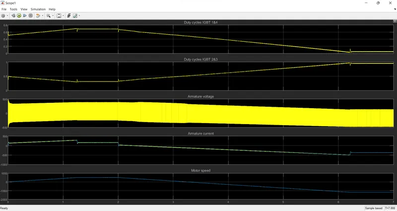
In the above graph we can observe the Duty Cycles IGBT 1&4, Duty Cycles IGBT 2&3, Armature Voltage, Armature Current and Motor Speed. When the Armature Current and Voltage increases simultaneously motor speed increased. If the current and voltage decrease motor speed decreased.
7.B. Also, Design the parameters in excel sheet.
In this challenge we are design the excel sheet for Above assumed parameters and calculation are taken for the excel sheet calculations, as asked in question.
The parameters of Aircraft and Towing vehicle are taken for this calculation.
The excel sheet of parameters are shown below.
| AIRCRAFT | |
| Parameters | values |
| Mass in kg | 59000 |
| Frontal area in m² | 500.14 |
| Drag coefficient | 0.0235 |
| Airdensity in kg/m^3 | 1.225 |
| Coefficient of rolling resistance | 0.02 |
| Gravitation in m/s² | 9.8 |
| Rolling resistance force in N | 11564 |
| Speed in m/s | 8.89 |
| Airdrag force in N | 568.9434042 |
| Towing vehicle | |
| Mass in kg | 35000 |
| Frontal area in m² | 6.8 |
| Drag coefficient | 0.6 |
| Airdensity in kg/m^3 | 1.225 |
| Coefficient of rolling resistance | 0.02 |
| Gravitation in m/s² | 9.8 |
| Rolling resistance force in N | 6860 |
| Speed in m/s | 8.89 |
| Airdrag force in N | 197.5012179 |
| Total Rolling resistance force in N | 18424 |
| Total Airdrag force in N | 766.4446221 |
| Total Force acting in N | 19190.44462 |
| Total power in W | 170603.0527 |
| Motor | |
| Voltage | 600 |
| Current | 400 |
| Input Power | 240000 |
| Duty cycle | 0.710846053 |
The excel file is uploaded in the attachments.