Project-1: Powertrain for aircraft in runways
EV LIVE BATCH 21
PART A - QUES.1
The different terms represent different weights or masses. For each flight, the weights are taken into account for several reasons.
(MEW) - also known as Manufacturer's Weight Empty or Licensed Empty Weight.
It is the weight of the aircraft "as built and includes the weight of the structure, power plant, furnishings, installations, systems and other equipment that are considered an integral part of an aircraft. This excludes any baggage, passengers, or usable fuel.
(ZFW) Zero-fuel weight
This is the total weight of the airplane and all its contents (including unusable fuel), but excluding the total weight of the usable fuel on board. As a flight progresses and fuel is consumed, the total weight of the airplane reduces, but the ZFW remains constant.
Maximum zero fuel weight (MZFW) is the maximum weight allowed before usable fuel and other specified usable agents (engine injection fluid, and other consumable propulsion agents) are loaded.
(OEW) Operating empty weight
It is the basic weight of an aircraft including the crew, all fluids necessary for operation such as engine oil, engine coolant, water, unusable fuel and all operator items and equipment required for flight but excluding usable fuel and the payload.
Payload
It is the carrying capacity of an aircraft. It includes cargo, people, extra fuel. In the case of a commercial airliner, it may refer only to revenue-generating cargo or paying passengers.
Maximum take off weight (MTOW)
This is the maximum weight at which the pilot of the aircraft is allowed to attempt to take off.
Regulated takeoff weight (RTOW)
Depending on different factors (eg, flap setting, altitude, air temperature, length of runway), RTOW or maximum permissible takeoff weight varies for each takeoff. It can never be higher than MTOW.
Maximum Landing Weight (MLW)
The maximum weight at which an aircraft is permitted to land. The foloowing image depicts takeoff weight components:
(MRW) also called maximum taxi weight (MTW)
It is the maximum weight authorized for maneuvering (taxiing or towing) an aircraft on the ground.
Aircraft gross weight.
It is the total aircraft weight at any moment during the flight or ground operation. This decreases during flight due to fuel and oil consumption
a) Crew weight (Wc)
The crew comprises the people necessary to operate the airplane in flight.e.g. Pilot, Co-pilot, Airhostess etc.
b) Payload weight (Wp)
The payload is what the airplane is mentioned to transport passengers, baggage, freightetc. (Military use the payload includes bombs, rockets and other disposable ordnance).
c) Fuel weight (W1)
This is the weight of the fuel in the fuel tanks. Since fuel is consumed during the course offlight. is a variable, decreasing with time during the flight.
d) Empty weight (We)
This is weight of everything else-the structure engines (with all accessory equipment), electronic equipment landing gear, fixed equipment and anything else that is not crew, payloador fuel.
e) Gross weight (Wo)
The sum of these weights is the total weight of the airplane. Gross weight or total weightvaries through the flight because fuel is being consumed. The design take off gross weight is theweight of the airplane at the instant it begins its mission. It includes the weight of the fuel.
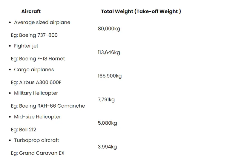
Different types of aircrafts with their weight:
QUES.2
Ground speed is the airplane's speed relative to the surface of the Earth,
airspeed (at least true airspeed) - is its speed relative to the air it is flying in.
As mentioned above, true airspeed is simply the speed at which an aircraft is moving relative to the air it is flying in. As such, it's also the speed at which the air is flowing around the aircraft's wings.
Ground speed, on the other hand, is the aircraft's speed relative to the ground. One thing that should be noted here is that it's its horizontal rather than vertical speed - an aircraft climbing completely vertically would have a ground speed of zero.
In other words, while airspeed is what determines whether there is enough airflow around an aircraft to make it fly, ground speed is what determines how fast an aircraft will get to its destination.
QUES. 3
Engine power is used all the time to move aircraft on the ground. I think you mean in the ramp area. if, so, again, engine power s used all the time in the ramp. They do get pushed back because only aircraft with engines on the tail can power-back due to FOD Sometimes, if it's a tight area, a tug will be used.
Aircraft can move using their own engine power all the time on the airport apron and taxiways under their own power to go towards runways and after landing taxi to their assigned gate. But the thrust produced resulting jet blast might cause damage to the terminal building or equipment. Engines close to the ground may also blow sand and debris forward and then suck them into the engine, causing damage to the engine. A pushback is therefore the preferred method to move the aircraft away from the gate. And also it can reduce the cost for fuel. Taxing can save money.
QUES. 4
Airplanes have engines, and they can use them to move forward along the ground. So they push themselves to the runway.
It is true that most of the time, a small vehicle is needed to push the larger commercial airplanes backwards away from the terminal building, because even if a plane can revere its thrust, it's not always safe to hit the buildings with that reverse thrust. So, the little trucks push the bugger planes back away from the buildings, but after that, the planes can apply a small amount of engine power to roll forward just as all airplanes can. Aircraft push themselves on the runaway
QUES. 5
Take off performance can be predicted using a simple measure of the acceleration of the aircraft along the runway based on force equilibrium.
The forces involved will be,
T- Thrust of propulsion system pushing aircraft along runway.
D-Aerodynamic Drag of vehicle resisting the aircraft motion.
F-Rolling resistance friction due to the contact of wheels or skids on the ground.
During take-off run the imbalance in these forces will produce an acceleration along the runway.
dV/dt = (T-D-F)/m
where dv/dt is the acceleration along the runway and m is the mass of the vehicle.
- Rotation Velocity.
The procedure for take-off will be that the vehicle will accelerate until it reaches a safe initial flying speed, the pilot can then rotate the vehicle to an attitude to produce climb lift and it will ascend from the ground. The determination of this safe flying speed or rotation speed. V. is a critical factor in determining take-off performance.
For safety reasons VR is usually determined as being 1.2*VSTALL or 1.1*Vmin control whichever is greater.
Stall speed, VSTALL is the lowest speed that the aircraft can be flown before the airflow starts to separate from wings as the angle of attack becomes too great, it can be calculated based on knowledge of the aircraft take-off configuration and hence the maximum achievable lift coefficient CL(max),
To maintain level flight the lift produced must equal the weight, at the point just before stall this leads to the following balance,
W = L = CL(max)* ½*rho*VSTALL2*S
hence stall speed can be calculated as,
VSTALL = [W/( CL(max)* ½* rho*S)]1/2
Minimum control speed, VMINCONTROL is a more complex calculation and requires knowledge of the stall characteristics of the tailplane and elevator. For conventional aircraft there is only a small difference between VR calculations based on stall speed or minimum control speed.
- Rolling Resistance
The friction between aircraft and runway will be proportional to the normal force exerted by the aircraft on the runaway.
The rolling resistance force is mainly experienced by the tire when the vehicle moves over any surface. Thre rolling resistance force is given by the expression: Frr = urr* (m*g)
where, m*g is weight in newtons
urr = coefficient of rolling resistance
The coefficient of rolling resistance depends on many factors like temperature, tire temperature, the material of the tire, threaded pattern of the tire, and also the road roughness and liquid on the road. These factors determine the rolling resistance force.
Tyre pressure:
The pressure generally is very high in an aircraft time to reduce the rolling resistance and to withstand the weight, usually, it will be around 200 to 300psi of pressure and they change based on the type of the aircraft. Tests of airliner aircraft tires have shown that they are able to sustain the pressure of a maximum of 800 psi. Aircraft tires are usually inflated with nitrogen to minimize expansion and contraction from the extreme changes in the ambient temperature and pressure experienced during flight
Brake force while landing
Stopping a 200-tonne aircraft landing at 180 mph requires a lot of braking force. To do this either hydraulic brakes or electric brakes are used. Hydraulic brakes put on weight of the aircraft. Now a days designers use electric brake system. The aim of brake force when landing is to minimise the distance.
The touch down velocity should be approximately the stall speed of the aircraft in landing configuration. This will be achieved by increasing the drag and decelerate the aircraft to minimum flying speed. The deceleration on the landing roll from to will be accomplished by braking and reverse thrust. This can be solved by the average acceleration approach that was used to estimate the take-off roll.
dv/dt = (-T -D -F)/m
Where, T - Thrust of propulsion system pushing aircraft along runway.
D - Aerodynamic Drag of vehicle resisting the aircraft motion.
F - Rolling resistance friction due to the contact of wheels or skids on the ground.
m - Mass
So, the brake force = Mass*Deceleration
QUES. 7
Description
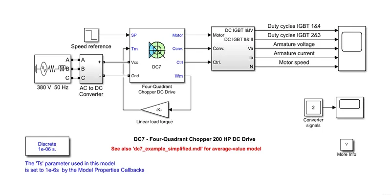
The 200 HP DC motor is separately excited with a constant 150 V DC field voltage source. The armature voltage is provided by an IGBT converter controlled by two Pl regulators. The converter is fed by a 515 V DC bus obtained by rectification of a 380 V AC 50 Hz voltage source. In order to limit the DC bus voltage during dynamic braking mode, a braking chopper has been added between the diode rectifier and the DC7 block.
The first regulator is a speed regulator, followed by a current regulator. The speed regulator outputs the armature current reference (in p.u.) used by the current controller in order to obtain the electromagnetic torque needed to reach the desired speed. The speed reference change rate follows acceleration and deceleration ramps in order to avoid sudden reference changes that could cause armature over-current and destabilize the system. The current. regulator controls the armature current by computing the appropriate duty ratios of the 5 kHz pulses of the four IGBT devices (Pulse Width Modulation). For proper system behaviour, the instantaneous pulse values of IGBT devices 1 and 4 are opposite to those of IGBT devices 2 and 3. This generates the average armature voltage needed to obtain the desired armature current. In order to limit the amplitude of the current oscillations, a smoothing inductance is placed in series with the armature circuit.
OUTPUT:
SIMULATION
Before starting the simulation, set the initial bus voltage to 515 V via the GUI block ('Initial States Setting' button and 'Cbus' variable).
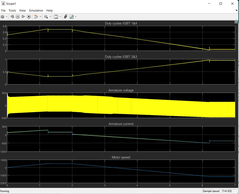
Start the simulation. You can observe the motor armature voltage and current, the four IGBT pulses and the motor speed on the scope. The current and speed references are also shown.
The motor is coupled to a linear load, which means that the mechanical torque of the load is proportional to the speed.
The speed reference is set at 500 rpm at t=0 s. Observe that the motor speed follows the reference ramp accurately (+400 rpm/s) and reaches steady state around t = 1.3 s.
The armature current follows the current reference very well, with fast response time and small ripples. Notice that the current ripple frequency is 5 kHz.
At t = 2 s, speed reference drops to -1184 rpm. The current reference decreases to reduce the electromagnetic torque and causes the motor to decelerate with the help of the load torque.
At t = 2.2 s, the current reverses in order to produce a braking electromagnetic torque (dynamic braking mode). This causes the DC bus voltage to increase.
At t = 3.25 s, the motor reaches 0 rpm and the load torque reverses and becomes negative. The negative current now produces an accelerating electromagnetic torque to allow the motor to follow the negative speed ramp (-400 rpm/s). At t = 6.3 s, the speed reaches -1184 rpm and stabilizes around its reference.
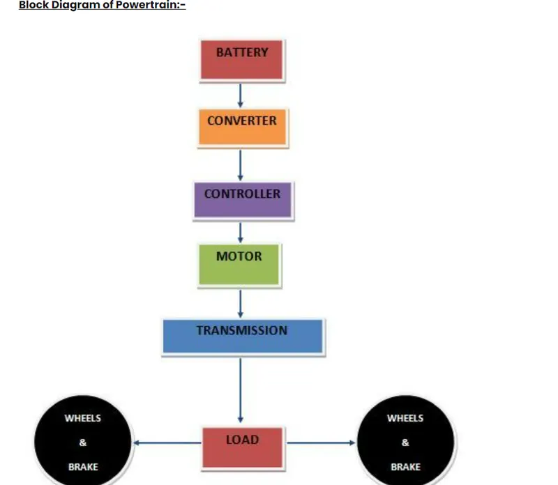
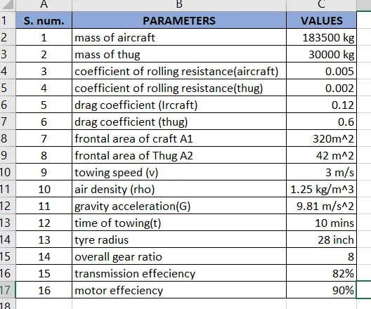
now, we assume that
Tyre radium to be = 28 inch = 0.7112 m
Torque required at wheel = total force*radius
= 9.95*0.7112
= 7.076 kNm
Motor torque = (wheel torque)/(gear ratio*effeciency)
assuming, gear ratio to be 8 and transmission effeciency 82%
= 7.076/(8*0.82)
= 1.079 kNm
if motor was at 90% effeciency, then motor torque = 1.198 kNm
Power required by motor will be = 29.84/(0.82*90) = 40.43 kW
and, total energy consumed = 40.43*0.1667 [time to be 10mins]
= 6.77 kWh
choosing a battery whose power rating is around 60 kW
Therefore, the duty cycle range to control the speed from zero to high speed is
d = req. power/rated power
= 40.43/60
= 0.67
this means, the controller should provide a duty cycle ranging from 0 to 67% to control towing speed
parametrs in excel