Project-1: Powertrain for aircraft in runways
Project-1
Powertrain for aircraft in runways
AIM:
Part A:
- Search and list out the total weight of various types of aircrafts.
- Is there any difference between ground speed and air speed?
- Why is it not recommended to use aircraft engine power to move it on the ground at Airport?
- How an aircraft is pushed to runway when its ready to take off?
- Learn about take-off power, tyre design, rolling resistance, tyre pressure, brake forces when landing.
Part B:
- A. With necessary assumptions, calculate the force and power required to push / pull an aircraft by a towing vehicle.
- Develop the model for the calculated force and power using Simulink.
- A. Design an electric powertrain with type of motor, it’s power rating, and energy requirement to fulfil aircraft towing application in Simulink. Estimate the duty cycle range to control the aircraft speed from zero to highest. Make all required assumptions. Prepare a table of assumed parameters. Draw a block diagram of powertrain.
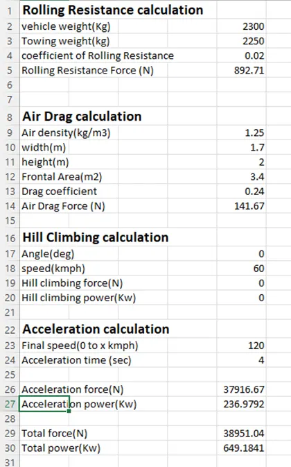
- Also, Design the parameters in excel sheet.
PART – A
1.List out the total weight of various types of aircrafts:
Weight is a major factor in airplane construction and operation, and it demands respect from all pilots and particular diligence by all maintenance personnel. Excessive weight reduces the efficiency of an aircraft and the available safety margin if an emergency condition should arise. The total weight is the maximum take- off weight. It is the maximum mass at which the aircraft is certified for take-off due to structural or other limits.
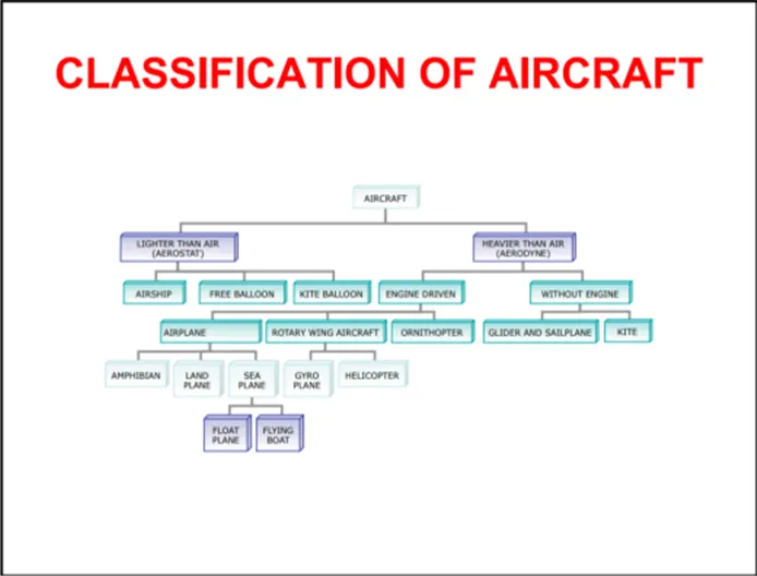
Airplanes can weigh between 2,000 pounds (907 kg) for a small Cessna, to upwards of over 1 million pounds (453,592 kg) during take-off for an Airbus A380.
These are some lists of total take-off weights of an aircraft:
- Airbus A330-800F – 1,117,882 pounds (507,063 kg)
- Boeing 747-400 – 875,014 pounds (396,900 kg)
- Lockheed C-5 Galaxy – 839,961 pounds (381,000 kg)
- McDonnel Douglas MD-11 – 602,523 pounds (273,300 kg)
- Boeing 767-400ER – 449,743 pounds (204,000 kg)
- Concorde – 407,855 pounds (185,000 kg)
- Boeing 727-100 – 159,835 pounds (72,500 kg)
The heaviest airplane in existence today is the Antonov An-225. It carries a maximum take-off weight of 1,280,000 pounds (580,598 kg).
2.Is there any difference between ground speed and air speed?
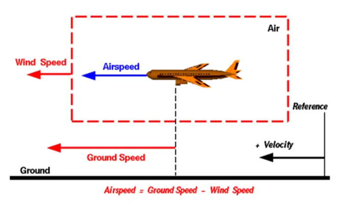
The relationship between airspeed and ground speed is fairly simple. Ground speed is simply the sum of airspeed and wind speed. On the other hand, if the wind is blowing against the direction the aircraft is traveling in, the aircraft experiences headwind, and its ground speed is lower than its airspeed. True Airspeed (TAS) is the indicated Airspeed corrected for nonstandard pressure and temperature. It reflects the actual speed of the relative airflow over the aircraft. In still air, the TAS is equal to the groundspeed. Groundspeed is the speed the aircraft is crossing over the ground. Ground speed is the horizontal speed of an aircraft relative to the ground. An airspeed indicator indicates the aircraft's speed relative to the air mass. The air mass may be moving over the ground due to wind, and therefore some additional means to provide position over the ground is required. And this is ground speed in aviation.
Airspeed is the vector difference between the ground speed and the wind speed. On a perfectly still day, the airspeed is equal to the ground speed. But if the wind is blowing in the same direction that the aircraft is moving, the airspeed will be less than the ground speed.
To measure ground speed:
Ground speed can be determined by the vector sum of the aircraft's true airspeed and the current wind speed and direction; a headwind subtracts from the ground speed, while a tailwind adds to it. Winds at other angles to the heading will have components of either headwind or tailwind as well as a crosswind component.
Airspeed vs. Ground Speed:
Airspeed is simply the speed at which an aircraft is moving relative to the air it is flying in. As such, it’s also the speed at which the air is flowing around the aircraft’s wings.
Ground speed, on the other hand, is the aircraft’s speed relative to the ground. One thing that should be noted here is that it’s its horizontal rather than vertical speed – an aircraft climbing completely vertically would have a ground speed of zero.
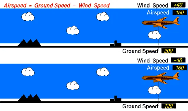
In other words, while airspeed is what determines whether there is enough airflow around an aircraft to make it fly, ground speed is what determines how fast an aircraft will get to its destination.
3.Why is it not recommended to use aircraft engine power to move it on the ground at Airport?
Aircraft can move using their own engine power all the time on the airport apron and taxiways under their own power to go towards runways and after landing taxi to their assigned gate. But, the thrust produced resulting jet blast might cause damage to the terminal building or equipment. Engines close to the ground may also blow sand and debris forward and then suck them into the engine, causing damage to the engine.
Aircraft Ground Running is usually used to describe the operation of some or all of the engines of an aircraft, whilst on the ground, for the purpose of functionally checking the operation of either engines or aircraft systems. This usually takes place prior to the Release to Service of an aircraft from maintenance. Ground running may be carried out either prior to, during or after the rectification of a defect or scheduled work on an engine or an aircraft system, when this requires engines to be operating in order to assess its function. Although the aircraft may need to be taxied or towed to an approved ground running position under a clearance from ATC, most operators and maintenance organisations do not require pilots to be on board because aircraft technicians can be trained and approved for these duties.
The risks which may arise from engine ground running relate to the potential for loss of control of the aircraft by those persons occupying the pilot seats in the flight deck. In most cases, such persons will be maintenance personnel holding specific company-issued approval for the required tasks. The consequences of loss of control during taxi or towing are the same as apply to these operations generally and this article is concerned only with the risks arising from the static running of one or more aircraft engines. Unwanted consequences from such static running are mainly related to those arising from the unintended movement of the aircraft during engine running - effectively a loss of control - especially during high power engine running. Damage can occur to the aircraft itself, other aircraft nearby or to airside structures. In addition, there is a risk of injury to ground support personnel who may be in relatively close proximity to the aircraft.
4.How an aircraft is pushed to runway when its ready to take off?
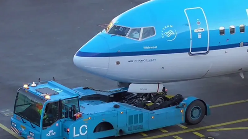
A so-called pushback truck reverses the aircraft into taxiing position, pushing it with a towbar attached to the nose-wheel strut. Or, in the most modern versions, by actually lifting the wheel. That speeds up coupling and decoupling. The aircraft taxis to the runway to depart at the agreed time.
- The pilot parks the aircraft in exactly the right place. Usually with the help of an automatic system, but occasionally guided by a marshaller waving two paddles or wands. Dozens of handling personnel are already standing by to perform a whole range of tasks simultaneously.
- As soon as the aircraft is stationary and the engines are switched off, the first priority is to disembark the passengers as quickly as possible. The apron handler places chocks in front of the wheels and connects the ground power. Meanwhile, the passenger bridge manoeuvres up to the door and a belt loader rolls up to the cargo hold. Luggage is unloaded and transferred to the terminal on baggage carts.
- Refuelling begins, usually from a hydrant at the stand. A hose is attached to this from a special vehicle called a dispenser, with the other side connected to the fuel tank in the wing. Read more about refuelling here.
- Now it is time to service the aircraft. The caterer loads new meals and takes away the food waste and used cutlery and crockery. Other activities include draining the lavatories, replacing the headrest covers, removing rubbish and distributing fresh blankets and in-flight magazine.
- A specialist team – or sometimes the crew themselves – cleans the cabin so that the new passengers aboard a pristine aircraft.
- Meanwhile, specialists from the airline conduct a technical check to make sure that the engines, wings, control surfaces, landing gear, instruments, doors and other equipment are in full working order.
- The aircraft is now ready for baggage to be loaded for the next flight. This is a quick process, on average taking only 10-15 minutes. A little later the passengers start boarding. As soon as they are all in their seats, the door is closed and the pilot informs air-traffic control that the flight is ready for departure.
- The apron handler removes the chocks. A so-called pushback truck reverses the aircraft into taxiing position, pushing it with a towbar attached to the nose-wheel strut. Or, in the most modern versions, by actually lifting the wheel. That speeds up coupling and decoupling.
- The aircraft taxis to the runway to depart at the agreed time.
- The pilot waits for permission to take off from air-traffic control. This is possible once the departure route is clear. As soon as the go-ahead is received, the plane takes to the air at full power.
5.Learn about take-off power, tyre design, rolling resistance, tyre pressure, brake forces when landing.
Take-off power:
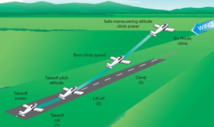
For light aircraft, usually full power is used during take-off. Large transport category (airliner) aircraft may use a reduced power for take-off, where less than full power is applied in order to prolong engine life, reduce maintenance costs and reduce noise emissions. In some emergency cases, the power used can then be increased to increase the aircraft's performance.
On take-off, in order to position the aircraft to a safe height away from terrain and obstacles (i.e. a flight path of maximum height and minimum ground distance desired), the engine thrust is set to a high ‘take-off power’ setting (although this is not necessarily full power) and the aircraft attitude is pitched up to maintain a specific speed (usually in the region of V2 + 15kts). Once the ‘safe height’ is reached the engine thrust can therefore be reduced to a more appropriate (i.e., efficient) setting and the aircraft flight path can be changed to a more appropriate (i.e., efficient) flight path.
In order to achieve that described above and also to provide minimum noise disturbance to the area surrounding the airport, regulatory procedures require aircraft to fly one of the two profiles given below during every departure. The aerodrome briefing pages will state which one of the two profiles is to be flown at each particular airport:
- At 1,500ft aal reduce thrust to climb power and accelerate the aircraft towards 250 knots, retracting flaps and slats.
- At 1,500ft aal reduce thrust to climb power maintaining V2 + 15kts. At 3,000ft accelerate the aircraft.
Operator’s SOPs must therefore enable the above procedures to be flown and, as such, controllers will witness flight crews performing certain actions and verbal SOP callouts during the initial climb in order to accomplish this. Aircraft that have highly automated systems will perform the thrust reduction and acceleration manoeuvre with minimal input from the flight crew. Note that the flight crew must input the required data into the FMS during the pre-flight procedure to enable such aircraft to accomplish this. In such aircraft it may be the case that the only physical action required by the flight crew is to move the flap lever, the remainder of the actions are of a monitoring nature to ensure that the correct Flight Mode Annunciator (FMA) modes engage and that the aircraft physically performs the manoeuvre correctly. In less automated aircraft it will require an increased amount of button pushing, knob turning and verbal calls to perform the thrust reduction and acceleration manoeuvre. During the initial climb, at the heights stated above, the thrust reduction and acceleration procedure therefore gives rise to issues regarding increased workload in the flight deck.
In the physics realm Power = Mass x Acceleration x distance/time
To many it means "how much throttle”, which is how much fuel/time.
"Throttle" x prop efficiency = Thrust
This gives you a unit of Force that can be directly compared to glide data as follows:
Potential energy Mass x Gravity x altitude loss = Thrust x horizontal distance flown
This rearranged to Thrust = Mass x Gravity x altitude loss/horizontal distance flown
Thrust = force required for straight and level flight, expressed in "pounds or Newtons"
So, if your plane weighs 10 lb and glides 5:1, you need 2 lb of thrust for straight and level flight.
One would at least double, or even triple this for "take-off power", depending on your performance preferences. Sufficient "take-off power" will give a safe climb rate to avoid difficulties with downdrafts.
For example: my plane glides 5:1 at 60 mph or around 5000 feet/minute and loses 1000 feet/minute. At 10 lbs it was calculated to need 2 lbs of thrust for straight and level flight.
How much more thrust do we need to climb 500 feet per/minute. Again, the glide data provides a very good estimate, 2 lbs x 500 fpm/1000 fpm = 1 lb additional or 3 lbs total at 60 mph. Higher speeds with more drag, or lower speeds "behind the power curve" will require more than 3 lbs of thrust.
Tyre design:
Radial tires are the most modern design of aircraft tyres. It is a design that is similar to that of car tyres. Typically, the radial tyre offers more landings per tread and lighter weight than a bias tyre; though sometimes at the expense of retreat lives.
Radial tyre development:
Bridgestone engineers have applied their expertise in new areas and have successfully developed high performance radial tires. In service, these radial tires have seen outstanding results, enabling Bridgestone to supply radial tires for many new generation aircrafts. Currently available for the Boeing B777, B747-400ER, B767-400ER MLG tire, B737 NLG tire, the Airbus A320 family, and A330/A340 operators.
Bias Tyre Technology:
Among the centre’s most renowned achievements to date is the development of the Tension Control Optimization Theory (TCOT), a new theory of tire design which allows for the simultaneous improvement of several previously incompatible tire performance characteristics in radial truck and bus tires. Highly successful, this theory influenced the development of ACOT, or Aircraft Tire Tension Control Optimization Theory.
Incorporated into Bridgestone aircraft bias tires, this new theory created a technological revolution in tire design by providing greater overload durability and allowing for greater weight reduction.
Design and Construction of Aircraft tyre:
Carcass plies are used to form the tire. They are sometimes called casing plies. An aircraft tyre is constructed for the purpose it serves.
- They support the weight of an aircraft while it is on the ground.
- It also provides the necessary traction for braking and stopping of an aeroplane.
- Tyre also helps to absorb the shock of landing and provide cushioning the roughness of take-off, roll-out, and taxi operations.
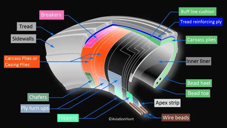
Unlike an automobile or truck tyre, it does not have to carry a load for a long period of continuous operation. However, an aircraft tyre absorbs the high impact loads of landing, and also, it’s operating at high speeds for a short time when required.
Rolling resistance:
The friction between aircraft and runway will be proportional to the normal force exerted by the aircraft on the runway.
f = µ (W – L)
the normal force will be the difference between weight (W) of aircraft and lift (L), the friction coefficient (µ) will be typically of a magnitude of 0.02 for a standard tarmac runway.
Tyre pressure:
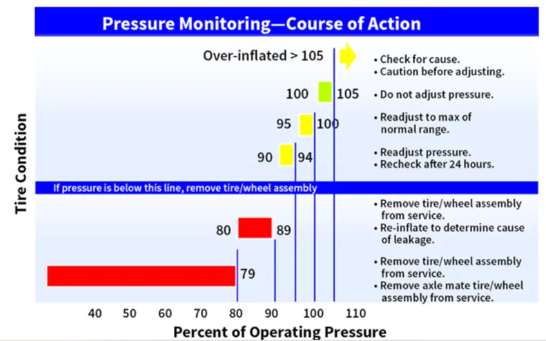
Rated pressure is the maximum inflation pressure to match the load rating. Aircraft tire pressures are given for an unloaded tire; i.e., a tire not on an airplane. When the rated load is applied to the tire, the pressure increases by 4% as a result of a reduction in air volume.
Inflation Pressure Requirements:
The goal of any inflation pressure maintenance program must be:
- To operate an aircraft with tire pressures within an “acceptable operating range”, and
- To address the “actual loss of inflation gas” from each tire/wheel assembly with the appropriate maintenance action.
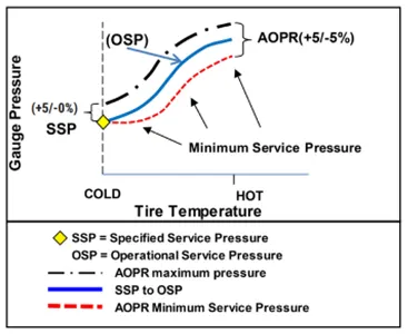
There are two scenarios that must be considered when determining if a tire is in the Acceptable Operating Pressure Range (AOPR) for dispatch:
- If the tire is “cold” (at the ambient temperature of the airport), then the Specified Service Pressure (SSP) should be used. The SSP is defined in the airplane maintenance manual (AMM) and is intended for “cold” (ambient) tires. Unless otherwise specified by the AMM, the SSP has a tolerance of plus 5%, minus 0%. In this case the SSP is equal to the AOPR.
- If the tire is “hot” due to rolling or braking thermal effects, then the tire’s Operational Service Pressure (OSP) must be higher than the SSP based on the temperature of the tire’s contained gas relative to the local ambient temperature. The tolerance on the OSP is plus 5%, minus 5%
Braking force when landing:
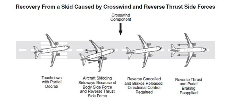
Many jet airplanes use reverse thrust to assist with braking during landings. Reverse thrust is a feature in jet engine airplanes that, as the name suggests, involves the reversal of the engines’ thrust. When flying, the thrust is projected out the rear of an airplane’s engines.
Airplanes rely on a braking system to safely land on runways. At cruising altitude, most commercial airplanes fly at a speed of roughly 500 to 600 mph. When landing, however, they must reduce their speed. A typical 747, for instance, has a landing speed of about 160 to 170 mph. And upon touching the runway, airplanes must quickly brake until they come to a complete stop. How do airplanes brake when landing exactly?
Wing Spoilers:
Many airplanes use wing spoilers to assist with braking when landing. Not to be confused with ailerons, spoilers are extendable flaps on the ends of an airplane’s wings. Pilots can raise the spoilers to decelerate the airplane as it approaches the runway. And even while on the runway, pilots will typically leave the wing spoilers raised. Raised wing spoilers create drag, which essentially slows down the airplane so that it’s able to brake more quickly.
Disc Brakes:
In addition to wing spoilers, airplanes use disc brakes. Airplane disc brakes are similar to the braking system in automobiles. They consist of a pair of callipers that, when engaged, squeeze pads against the rotors of an airplane’s landing gear. Disc brakes are designed to remain static at all times. In other words, they don’t rotate with the wheels of an airplane’s landing gear. As the wheels turn, the disc brakes will remain static and stationary. They are a vital component of an airplane’s braking system because they are designed to apply pressure to the airplane’s wheels. Disc brakes will squeeze the wheels, thereby slowing down the speed at which they spin. In turn, this reduces the speed of the airplane so that it can come to a complete stop on the runway.
Reverse Thrust:
Finally, many jet airplanes use reverse thrust to assist with braking during landings. Reverse thrust is a feature in jet engine airplanes that, as the name suggests, involves the reversal of the engines’ thrust. When flying, the thrust is projected out the rear of an airplane’s engines. When landing, however, pilots may use the reverse thrust feature. Reverse thrust changes the direction of the engines’ thrust. Rather than projecting out the rear, the thrust will be projected out the front. This reversal of thrust provides deceleration that allows airplanes to slow down more quickly when landing.
PART – B
6.A. With necessary assumptions, calculate the force and power required to push / pull an aircraft by a towing vehicle.
In order to calculate the tractive force and power required to push/pull aircraft by the towing vehicle, we need to understand the forces that acts on the towing vehicle which can be listed as follows,
- Force acting due to rolling resistance
- Force acting due to drag
A] Rolling resistance force (Frr)
The force due to rolling resistance experienced by towing vehicle carrying aircraft can be given by the formula as shown,
Frr = µrr*m*g
Where,
m = total mass of the towing vehicle + gross weight of the airplane (Kg)
g = gravitational acceleration (m/s²)
µ = coefficient of rolling resistance
The rolling coefficient of air tires on dry roads can be estimated by,
µrr = 0.005 + (1/p) * (0.001 +0.0095(v/100) ²)
where
µrr = rolling coefficient
p = tire pressure(bar)
v = velocity (Km/h)
coefficient of rolling resistance is affected by various factors such as tire pressure, tire diameter, tire width, tire construction, tire tread, surface roughness etc
let us assume the aircraft is being towed in this case be airbus A330,
Mass of A330, m1 = 240000Kg
Mass of towing vehicle, m2 = 15000 kg
Total mass, m = m1 + m2
m = 240000 + 15000 = 255000 kg
g = 9.81 m/s²
Assuming the tyre pressure (p) of 15 bar and vehicle velocity (v) as 10 kmph
µrr = 0.005 + (1/15) * (0.01 + 0.0095 * (10/100) ²)
µrr = 0.0056
Therefore, Frr = 255000 * 9.81 * 0.0056
Frr = 14010N or 14.01 KN
B] force due air drag:
The force due to air drag on toeing vehicle carrying aircraft can be given by the formula,
Fad = ½ * p* A * Cd * V²
Where,
p = density of air
A = frontal area
Cd = coefficient of air drag
v = velocity of towing vehicle with aircraft
let’s assume some values for the force calculation,
p = 1.225 kg
A = 20 m²
Cd = 0.0265
v = 10 Kmph or 2.78 m/s
Therefore, Fad = ½ * 1.225 * 20 * 0.0265 * (2.78) ²
Fad = 2.5N or 0.0025KN
Total tractive force required to tow the aircraft on the runway at a speed of 10 Kmph will be,
Fte = Frr + fad
Fte = 14.01 + 0.0025
Fte = 14.012KN
The power requires to pull/push the aircraft using towing vehicle will be,
p = Fte * v
p = 14.012 * 2.78
p = 39Kw
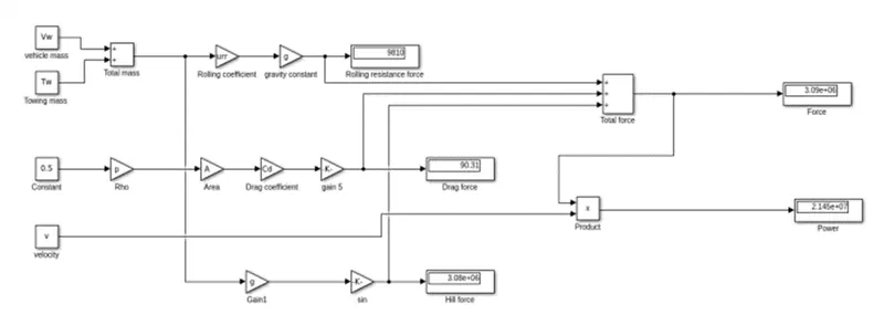
- Develop the model for the calculated force and power using Simulink.
MATLAB script:
% tow vehicle force and power calculations
clear all
clc
g = 9.81; %gravitational constant
urr = 0.01; %rolling resistance
Vw = 40000; % vehicle weight
Tw = 60000; % towing capacity
M = Vw+Tw; %total mass in Kg
Frr = M*urr*g; % rolling resistance force in N
p = 1.25; % Air density
Cd = 0.5; %drag coefficient
A = 6; % area of aero drag
v = 6.94; % velocity in m/s
Fad = 0.5*p*A*Cd*(v)^2 % Aerodrag force in N
Deg = 180; % hill climbing angle
Fhc = M*g*sin(Deg*3.14/108) % hill climbing force in N
Fte = Frr+Fad+Fhc % Total force in N;
Model:
7.A] Design an electric powertrain with type of motor, it’s power rating, and energy requirement to fulfil aircraft towing application in Simulink. Estimate the duty cycle range to control the aircraft speed from zero to highest. Make all required assumptions. Prepare a table of assumed parameters. Draw a block diagram of powertrain.
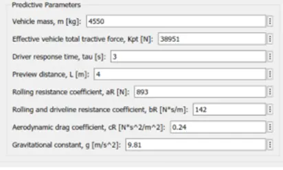
Here I assume Tesla model X:

Tire radius is 0.37
Total torque = f*r
= 38951 * 0.37
T = 14411.87 N.m
Power required for motor
P = f * v
= 38951 * 60 *5/18
P = 649.18 kw
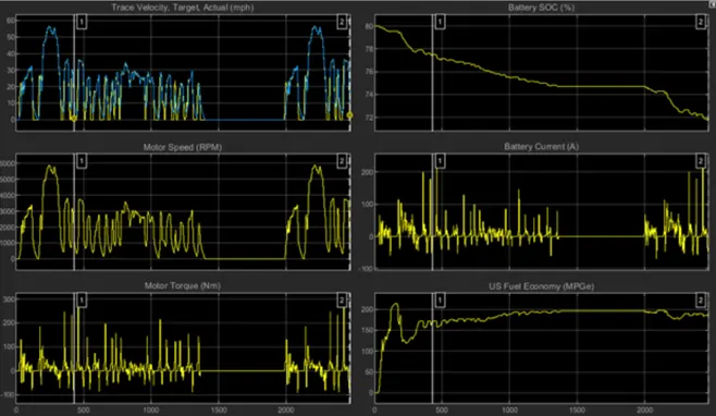
Electric powertrain model:
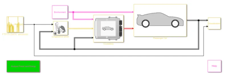
Longitudinal vehicle assumptions:
Tesla x car dual motor AWD 60 D is used:
Both the 60D save two tenths off their acceleration and quarter-mile times and add 10 miles of range, the latter thanks to the additional regain capacity from the second motor. The 85D will now travel 295 miles on the single charge – tantalizingly close to the magic 300-mile mark. The 60D will travel 225 miles before needing to be plugged back in.
There’s autopilot too, a spookily sophisticated semi-autonomous drive system. The car senses road signs with an optional camera and a 360-degree sonar keeps an eye on barricades and traffic. When traffic slows so does the tesla even to dead stop. Lanes can be changed with a flick of the turn-signal indicator stalk. When the car isn’t doing the driving, the model S will provide feedback through the steering wheel if you merge isn’t up to snuff’
Top speed:
60D:125 mph (vs 120 mph for 60Kwh)
85D:155 mph (vs 125 mph for 85 Kw)
P85D:155 mph (vs 130 mph for p85)
0-60 mph acceleration:
60D:5.7 sec (vs 5.9 sec)
85D:5.2 sec (vs 5.4 sec)
P85D:3.2 sec (vs 4.2 sec)
Quarter mile times:
60D:14 sec (vs 14.2 sec)
85D:13.5 sec (vs 13.7 sec)
P85D:11.8 sec (vs 12.6 sec)
Torque:
60D:362 lb-ft-181 lb-ft front, 181 lb-ft rear
85D:362 lb-ft-181 lb-ft front, 181 lb-ft rear
P85D:687 lb-ft – 244 lb-ft front, 443 lb-ft rear
Electric motor output:
60D:376 hp-188hp front, 188 hp rear (vs 380 hp rear)
85D:376hp-188hp front, 188 hp rear (vs 470 hp)
P85D:691hp – 221 hp front, 470 hp rear (vs 470 hp)
Weight:
60D:255 miles (vs 215 miles)
85D:295 miles (vs 285 miles)
P85D:275miles (vs 285 miles)
Battery range:
60D:225 miles (vs 215 miles)
85D:295 miles (vs 285 miles)
P85D:275 miles (vs 285 miles)
So, the phase asynchronous motor is to be used.
B] Design the parameters in excel sheet.