Project-1: Powertrain for aircraft in runways
Part A:
1. Search and list out the total weight of various types of aircrafts.
Part A:
1. Search and list out the total weight of various types of aircrafts.
The aircraft has following weight:
- Payload weight: it is load carrying capacity of an aircraft including passenger, extra fuel and cargo, but if it is case of cargo plane include the total load of logistics luggage which is need to transport. In the commercial airline they refers only to revenue generating cargo and paying consumers.
- Aircraft Gross weight: it is the total aircraft weight at any moment during the flight or ground operation. This decreases during flight due to fuel and oil consumption.
- Zero fuel weight (ZFW): This is the total weight of the aircraft include unusable fuel, but excluding the total weight of the usable fuel at board.
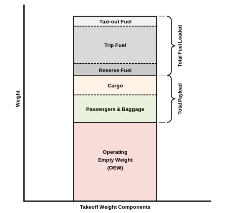
- Maximum takeoff weight (MTOW): this is the maximum weight at which the aircraft will be made takeoff.
- Manufactures empty weight (MEW): The MEW is usually fixed for a specific aircraft and only gets changed during maintenance or operational changes.
- Maximum ramp weight (MRW): it is the maximum weight authorized for taxiing and towing, an aircraft on the ground.
- Maximum landing weight (MLW): This maximum weight at which an aircraft is permitted to land.
- Regulated takeoff weight (RTOW): depend on different factors such as flap setting, altitude, air temperature, length of runway. RTOW or maximum permissible takeoff weight varies for each takeoff. It can never be higher than MTOW.
|
Type |
MTOW [kg] |
MLW [tones] |
TOR [m] |
LR [m] |
||
|
640,000 |
591.7 |
3500 |
Heavy |
Super |
||
|
589,670 |
3660 |
Heavy |
Super |
|||
|
575,000 |
394 |
3100 |
1930 |
Heavy |
Super |
|
|
447,700 |
346.091 |
3100 |
1800 |
Heavy |
Heavy |
|
|
443,613 |
306.175 |
3100 |
Heavy |
Heavy |
||
|
412,770 |
295.742 |
3090 |
Heavy |
Heavy |
||
|
Antonov An-124-100M |
405,060 |
330 |
2520 |
900 |
Heavy |
Heavy |
|
396,900 |
295.742 |
3018 |
2179 |
Heavy |
Heavy |
|
|
381,000 |
288.417 |
2530 |
1494 |
Heavy |
Heavy |
|
|
377,840 |
285.700 |
3338 |
2109 |
Heavy |
Heavy |
|
|
377,840 |
260.320 |
3222 |
1905 |
Heavy |
Heavy |
|
|
371,950 |
240 |
3050 |
2010 |
Heavy |
Heavy |
|
|
367,400 |
256 |
3100 |
2100 |
Heavy |
Heavy |
|
|
347,800 |
260.816 |
2830 |
Heavy |
Heavy |
||
|
351,800 |
251.29 |
3100 |
Heavy |
Heavy |
||
|
347,450 |
223.168 |
3000 |
Heavy |
Heavy |
||
|
340,200 |
265.300 |
Heavy |
Heavy |
|||
|
308,000 |
233.5 |
Heavy |
Heavy |
|||
|
299,370 |
237.683 |
3380 |
Heavy |
Heavy |
||
|
297,550 |
213.00 |
3380 |
1550 |
Heavy |
Heavy |
|
|
276,700 |
190 |
3000 |
1926 |
Heavy |
Heavy |
|
|
273,300 |
185 |
2990 |
1890 |
Heavy |
Heavy |
|
|
270,000 |
175 |
2670 |
1860 |
Heavy |
Heavy |
|
|
270,000 |
195.04 |
3115 |
2118 |
Heavy |
Heavy |
|
|
256,280 |
183 |
2990 |
1890 |
Heavy |
Heavy |
|
|
254,000 |
192.777 |
2900 |
Heavy |
Heavy |
||
|
254,000 |
201.849 |
Heavy |
Heavy |
|||
|
253,500 |
181 |
2990 |
Heavy |
Heavy |
||
|
251,000 |
191 |
3100 |
Heavy |
Heavy |
||
|
250,000 |
175 |
2600 |
1980 |
Heavy |
Heavy |
|
|
242,000 |
185 |
2500 |
1750 |
Heavy |
Heavy |
|
|
242,000 |
180 |
2220 |
1750 |
Heavy |
Heavy |
|
|
231,300 |
166.92 |
2636 |
Heavy |
Heavy |
2. Is there any difference between ground speed and air speed?
Generally speaking, there are two different types of speed when talking about airplanes – ground speed and airspeed. While ground speed is the airplane’s speed relative to the surface of the Earth, airspeed – at least true airspeed – is its speed relative to the air it is flying in. Below, I will explain the two types of speed in more detail, as well as talk about the four types of airspeed that are commonly used.
Air speed VS ground speed:
Ground speed: Ground speed is how fast an airplane is travelling relative to a fixed point on the ground
It is the speed of how fast an airplane shadow would move across the land. If there a strong wind pushing an aircraft the reflected in the ground.
Air speed: Airspeed is the how fast an airplane is really flying strictly under its own power which is the actual velocity of the aircraft.
As mentioned above, true airspeed is simply the speed at which an aircraft is moving relative to the air it is flying in. As such, it’s also the speed at which the air is flowing around the aircraft’s wings. Ground speed, on the other hand, is the aircraft’s speed relative to the ground. One thing that should be noted here is that it’s its horizontal rather than vertical speed – an aircraft climbing completely vertically would have a ground speed of zero. In other words, while airspeed is what determines whether there is enough airflow around an aircraft to make it fly, ground speed is what determines how fast an aircraft will get to its destination.
(3) Why is it not recommended to use aircraft engine power to move it on the ground at Airport?
The movement on the ground the aircraft the aircraft used its own engine power that’s called as taxing.
taxing.
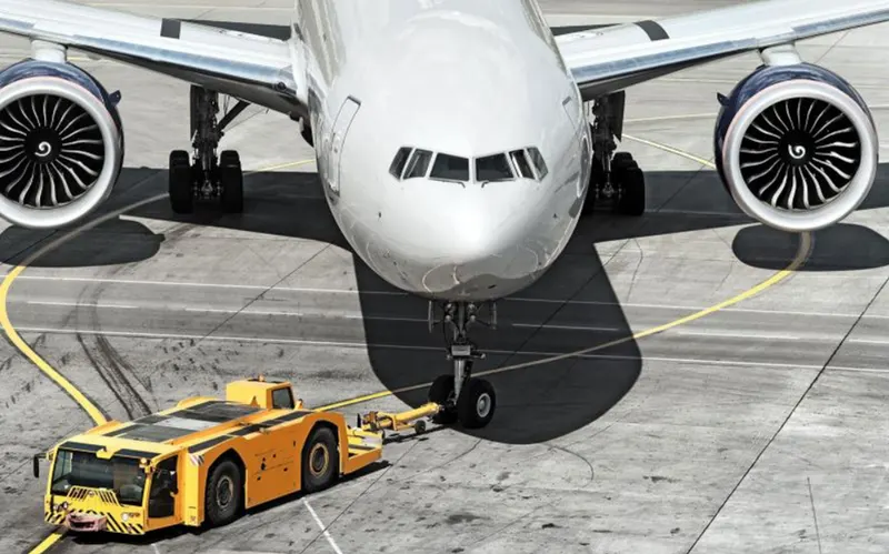
Many aircraft are capable of moving in backward using reverse thrust as result the jet blast or prop wash might cause damage to the terminal building or equipment. Engine close to the ground may also blow sand and debris forward and then suck them into the engine, causing damage to the engine. Therefore there are pushback trunk in the airport. A pushback truck lifts the front wheel of the aircraft, their role in most airports is move the aircraft away from the parking spot on to the taxiways, which is called towing.
- There is a risk of injury to ground support personnel who may be in relatively close proximity to the aircraft.
- The plane engine are very loud, when than one plane will add up their sound then it will not br pleasant for passengers and other near airport.
- It also saves fuel in which pushback trunk will move the aircraft all the way to runway to save the fuel and reduced impact of environment.
- Effectively loss of control can happen, specially during high power engine running. Damage can occur to the aircraft itself, other nearby or to airside structures.
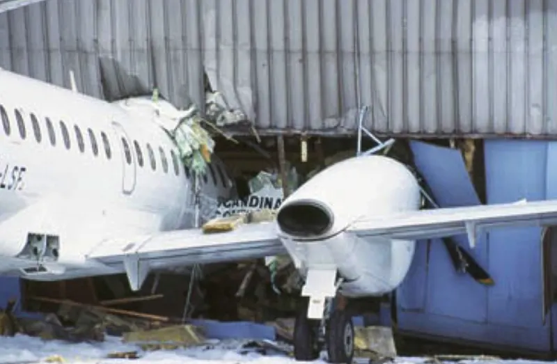
(4) How an aircraft is pushed to runway when its ready to take off?
Taxing: Taxiing is simply the process of moving an airplane while it’s on the runway. It occurs after an airplane has landed, and it occurs before an airplane takes off. Airplanes don’t actually fly while on the ground. As a result, the process by which they move on the runway isn’t known as flying; it’s known as taxiing.

Following the taxiways reaches the runway. Takeoff is the phase of flight in which an aircraft goes through a transition from moving along the ground to flying in the air, usually staring on a runway. usually engine are run at full power during takeoff. Following the taxi motion, the aircraft stops at the starting line of the runway. Before take off the engine particularly piston engine are routinely run up at high power to check for engine related problem. This make a considerable noise, when the pilot release the brakes the aircraft starts accelerating rapidly until the necessary speed for takeoff is achieved.
Towing:
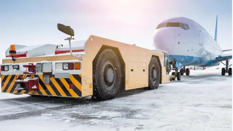
In the parking areas, where taxing the aircraft is not practical is unsafe, such as moving aircraft in and out of maintenance hangers or moving aircraft that are not under their own power or moving backward then towing aircraft is performed using the power of a specialized ground vehicle attached to or supports the nose landing gear. The traditional method of allowing the ground vehicle to move an aircraft is to attached it to the aircraft nose landing gear by means of towbar.
As the pilot can not see what is behind the aircraft steering is done by pushback tractor driver and depending on the aircraft type and airline procedure a bypass pin may be temporarily installed into the nose gear to disconnect it from the aircraft normal steering mechanism. Once the towing is completed the towbar is disconnected and the aircraft can taxing under its own power.
5)Learn about takeoff power, Tire design, rolling resistance, tyre pressure, brake forces when landing.
Takeoff power:
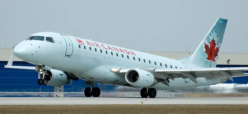
Takeoff is phase of flight in which an aircraft leaves the ground and becomes airborne. For light aircraft, usually full power is used during takeoff. Large transport category aircraft may use a reduced power for takeoff, where less than full power is applied in order to prolong engine life, reduce maintenance costs and reduce noise emissions. During emergency cases the power used can then be increased to increase the aircraft performance. Before takeoff, the engines, particularly piston engines, are routinely run up at high power to check for engine-related problems. The aircraft is permitted to accelerate to rotation speed The term rotation is used because the aircraft pivots around the axis of its main landing gear while still on the ground, usually because of gentle manipulation of the flight controls to make or facilitate this change in aircraft attitude.
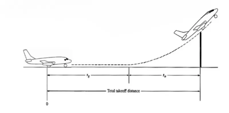
An airplane is motionless at the end of a runway. This is denoted by location O. The pilot releases the brakes and pushes the throttle to maximum takeoff power, and the airplane accelerates down the runway. At some distance from its starting point, the airplane lifts into the air. The distance the airplane covered along the runway before it lifts into the air is called the ground roll. The total takeoff distance also includes the extra distance covered over the ground after the airplane is airborne but before it clears an obstacle of 50 ft for military aircraft and 35 ft for commercial aircraft. This is denoted by Sa. The sum of Sa and Sg is the total takeoff distance.
Tyre design:
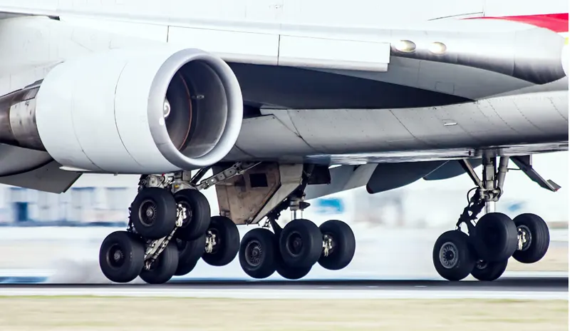
When it comes to safety, tire are one of the most important components of aircraft. They help to absorb the shock of landing and provide cushioning. It also provides the necessary traction for braking and stopping of an aircraft. An aircraft tire is designed to withstand extremely heavy loads while landing, take off, taxing, and parking. The number of wheels required for aircraft increases with the weight of the aircraft, as the weight of the aircraft needs to be distributed more evenly.
Carcass plies are used to form the tire. They are sometimes called casing plies. An aircraft tyre is constructed for the purpose it serves.
- It provides the necessary traction for braking and stopping of an aircraft.
- Tire also helps to absorb the shock of landing and provide cushioning the roughness of takeoff, roll-out, and taxi operations.
- They support the weight of an aircraft while it is on the ground.
aircraft tyre absorbs the high impact loads of landing, and also it’s operating at high speeds for a short time when required.
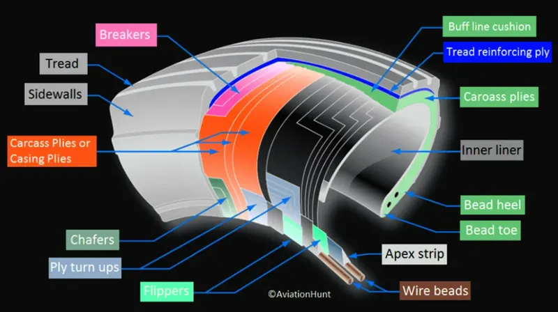
Sidewall: The sidewall is a protective layer of rubber that covers the outer casing ply. It extends from the tread edge to the bead area.
Tread Reinforcing Ply: One or more layers of fabric that strengthens and stabilizes the tread area for high-speed operation. It also serves as a reference for the buffing process when tires are retreaded.
Buff Line Cushion: The buff line cushion is made of rubber compound to enhance the adhesion between the tread reinforcing ply and the breakers or casing plies. It is of sufficient thickness to allow for the removal of the old tread when the tire is retreaded.
Breakers: Breakers are reinforcing plies of rubber-coated fabric placed under the buff line cushion to protect casing plies and strengthen and stabilize the tread area. They are considered an integral part of the casing construction.
Casing Plies: Alternate layers of rubber-coated fabric (running at opposite angles to one another) provide the strength of the tire.
Wire Beads: Hoops of high tensile strength steel wire that anchor the casing plies and provide a firm mounting surface on the wheel. The outer edge of the bead that fits against the wheel flange is called the bead heel. The inner bead edge is called the bead toe.
Apex Strip: A wedge of rubber affixed to the top of the bead bundle.
Flippers: Layers of rubberized fabric that help anchor the bead wires to the casing and improve the durability of the tire.
Ply Turnups: The casing plies are anchored by wrapping them around the wire beads, thus forming the ply turnups.
Chafer: A protective layer of rubber and/or fabric located between the casing plies and wheel to minimize chafing.
Liner: In tubeless tires, the liner is a layer of low permeability rubber that acts as a built-in tube and restricts gas from diffusing into the casing plies. In tube-type tires, a thinner liner is used to prevent tube chafing against the inside ply.
Casing Plies: As in bias-ply tires, the casing plies are layers of rubber-coated fabric. However, unlike those in bias plies that run at opposite angles to one another, radial plies run radially from bead to bead.
Chippers: The chippers are layers of rubber-coated fabric applied at diagonal angles that improve the durability of the tire in the bead area.
Beads: The tire bead areas should be inspected next to the wheel flanges for heat-induced damage, especially if brake drag or severe braking was experienced.
Rolling Resistance:
Rolling resistance is the energy that your vehicle needs to send to your tires to maintain movement at a consistent speed over a surface.
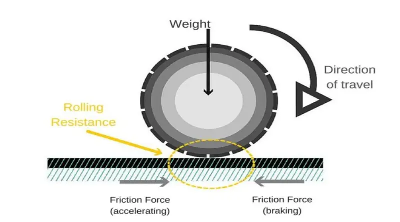
Rolling resistance force = F_rr= µ_rrr*m*g
Where
	µ_rrr=rolling resistance coefficient(varies for different type environmental             condition.
	 m = mass of the aircraft
	g = gravitational force constant (9.8 m/s^2)
in addition to the familiar force like thrust, weight, lift, drag this is rolling resistance force occurred by friction between tyre and ground. When aircraft is towing or taxing to pushed it into runway or when takeoff roll is happening the rolling resistance force act against the traction force of the aircraft.
This rolling resistance force depends on many factors like surface of road, roughness of the road, dry or wet condition of the road, tyre pressure, tyre material, thread pattern, temperature of tyre etc, which determine the rolling resistance force.
|
Type of runway surface |
Typical value of µ |
|
|
Rolling (brakes off, takeoff condition)
|
Brakes on (landing condition)
|
|
|
Wet grass |
0.08 |
0.2 |
|
Soft turf |
0.07 |
0.2 |
|
Firm turf |
0.04 |
0.3 |
|
Hard turf |
0.05 |
0.4 |
|
Icy concrete/asphalt |
0.02 |
0.06-0.10 |
|
Wet concrete/asphalt |
0.05 |
0.15-0.3 |
|
Dry concrete/asphalt |
0.03-0.06 |
0.3-0.5 |
Tyre pressure:
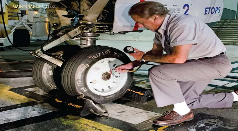
The pressure is generally is very high in an tire to reduced the rolling resistance and to withstand the weight. Usually the tyre pressure will be around 190 to 320psi based on the type of aircraft. The aircraft tyre are usually inflated with nitrogen to minimize expansion and contraction from extreme changes in ambient temperature and pressure experienced during flight.
According to U. S. federal aviation administration allowable pressure loss is 5% per day.
Large airliners are heavy. A Boeing 767 has a max takeoff weight of over 400,000 pounds. A fully loaded 747-8 weighs nearly a million pounds.
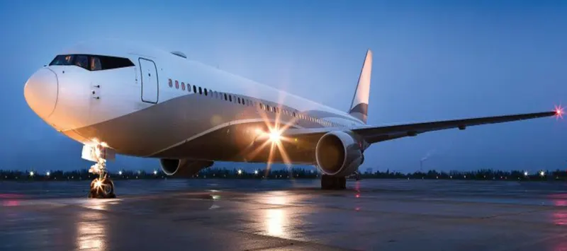
All that weight rides on a handful of tires. Automobile tires are pressurized to around 30-40 psi. If large aircraft tires were filled with 35 psi, they would be flat under the weight. Large aircraft tire pressures are ridiculously high. A Boeing 767-300 main wheel is inflated to 205 psi. The high pressure supports the tire’s maximum rated load of 51,000 lbs.
Brake force when landing:
Hit the brakes:
Aircraft brakes stop a moving aircraft by converting its kinetic energy to heat energy by means of friction between rotating and stationary discs located in brake assemblies in the wheels.
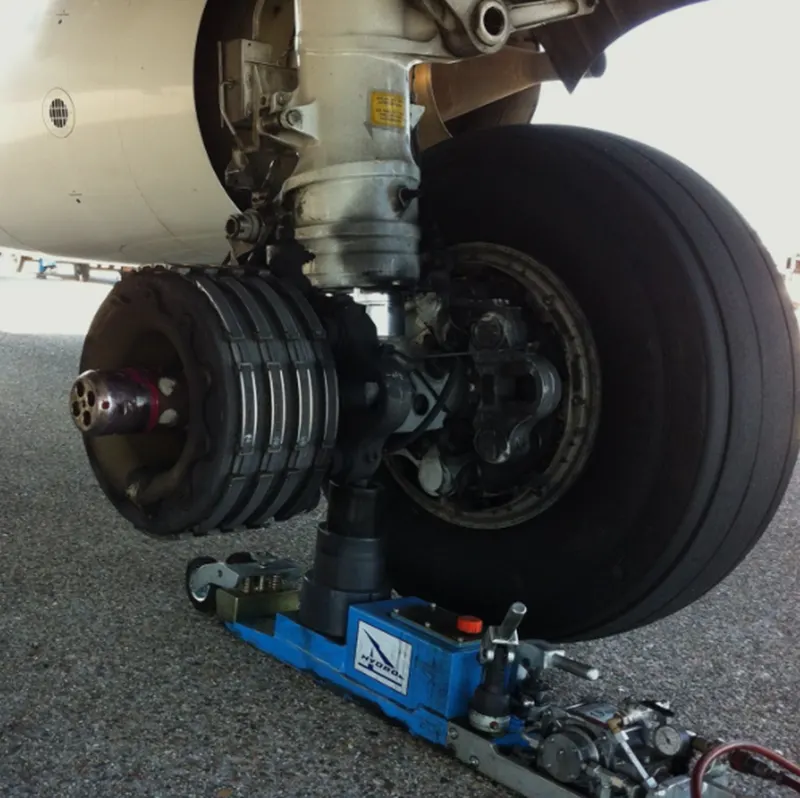
Brakes provide this critical stopping function during landings to enable airplanes to stop within the length of the runway. They also stop aircraft during rejected takeoff events, in which an attempted takeoff is canceled as the airplane is rolling down the runway before it lifts off from the ground due to engine failure, tire blowout, other system failure or direction from air traffic control.
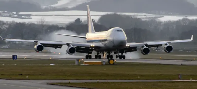
Aircraft brakes also prevent motion of the aircraft when it is parked, limit its speed during taxiing and can even help steer the aircraft on the ground by applying different levels of braking force to the left- and right-side brakes.
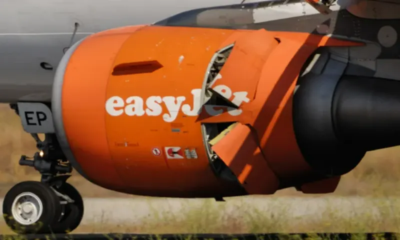
Aircraft brakes work in conjunction with other brake mechanisms such as thrust reversers, air brakes and spoilers. Thrust reversers are surfaces that are deployed into the path of the jet blast from the engines to redirect propulsive thrust in a direction that opposes the motion of the aircraft. Air brakes and spoilers are flight control surfaces that create additional aerodynamic drag when deployed into the path of air flowing around the aircraft.
Reverse thrust:
Reverse thrust is always selected manually, pull the thrust levers back and then lift the reverse thrust selector. And then control the amount of reverse thrust that we apply appropriate to the landing conditions.
Part B
(6)A. With necessary assumptions, calculate the force and power required to push / pull an aircraft by a towing vehicle.
The vehicle is push and pull condition only rolling resistance and aerodynamic force are applied, hill climbing force are neglected.
Rolling resistance force = F_rr= µ_rrr*m*g
Where
	µ_rrr=rolling resistance coefficient(varies for different type environmental             condition.
	 m = mass of the aircraft
	g = gravitational force constant (9.8 m/s^2)
Aerodynamic force =  1/2*ρ*A*C_d*V^2
Where
	ρ=Air density (Kg/m^3)
	A=frontal area (m^2)
	C_d=aero drag coefficient
	V = velocity (m/s)

Aircraft parameter:
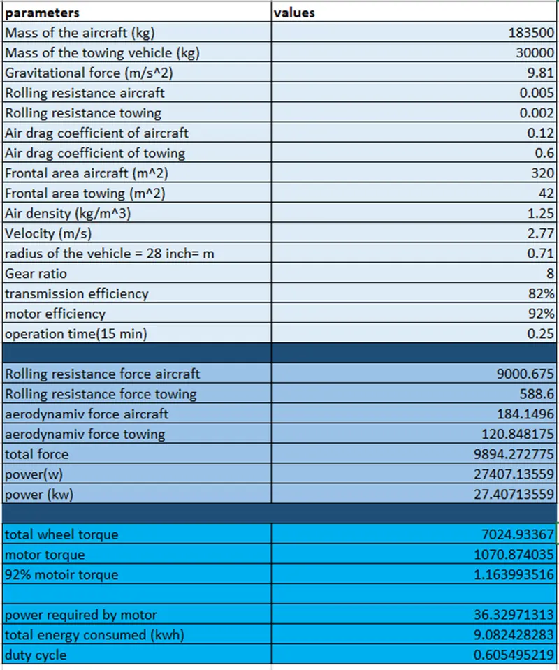
Mass of the aircraft (Ma) = 183500kg
Mass of towing vehicle = 30000kg
Gravitational force (g) = 9.81m/s^2
Rolling resistance of aircraft = 0.005
Rolling resistance of towing = 0.002
Air drag coefficient aircraft (Cd)= 0.12
Air drag coefficient towing (Cd)= 0.6
Frontal area aircraft = 320 m^2
Frontal area towing = 42 m^2
Air density(p) = 1.25kg/m^3
Velocity = 2.77m/s

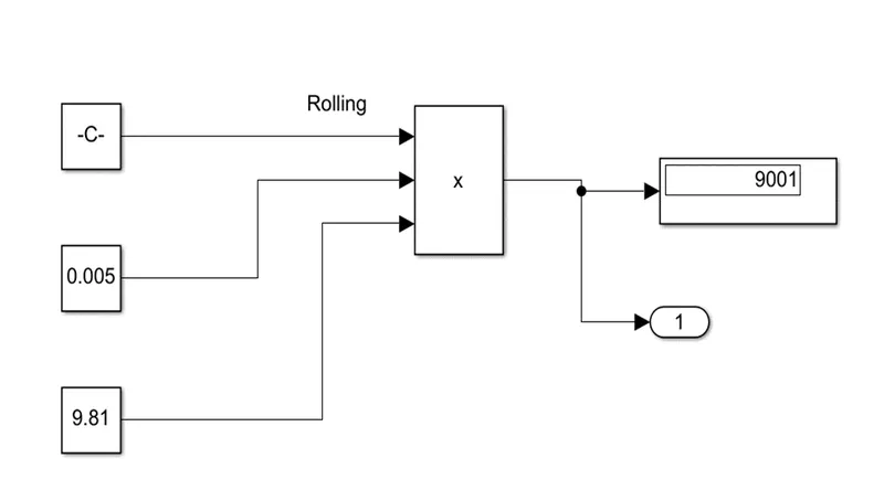
Rolling resistance force aircraft= F_rr= µ_rrr*m*g
                                                       = 0.005*183500*9.81
                                                       = 9000N
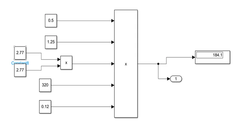
Aerodynamic force aircraft =  1/2*ρ*A*C_d*V^2
                                                   = 0.5*1.25*320*0.12*2.77*2.77
                                                    = 184 N
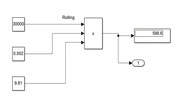
Rolling resistance force of towing = µ_rrr*m*g
                                                                = 30000* 0.002*9.81
                                                                 = 588.6 N
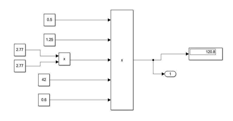
Aerodynamic force towing =  1/2*ρ*A*C_d*V^2
                                                 = 0.5*1.25*42*0.6*2.77*2.77
                                                = 	120.85 N
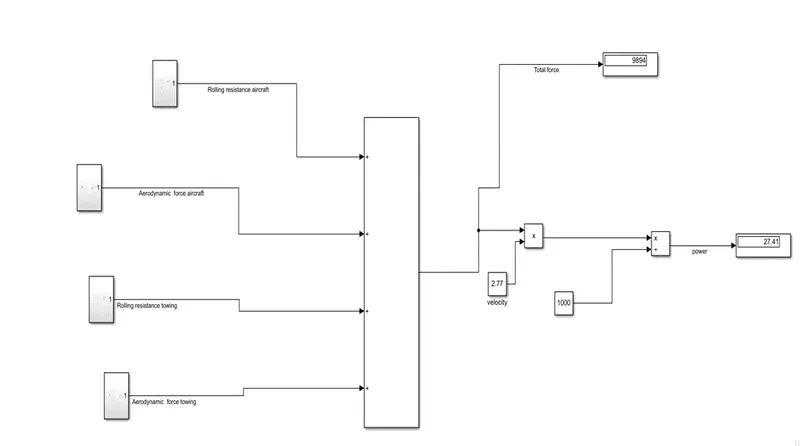
Total force = (Rolling resistance force aircraft+ Aerodynamic force aircraft+ Rolling   resistance force of towing+ Aerodynamic force towing)
                               = (9000+184+588.6+120.85)
                               = 9893.45

Power required in push/pull of aircraft =
   Power = (total force) * (velocity)
              = (9893.45) * (2.77)
              = 27404.85
             = 27.40485 kw
(B)Develop the model for the calculated force and power using Simulink.
Rolling resistance force aircraft:
Aerodynamic force aircraft:
Rolling resistance force of towing:
Aerodynamic force towing:
Simulation Model:
(7)A. Design an electric powertrain with type of motor, it’s power rating, and energy requirement to fulfill aircraft towing application in Simulink. Estimate the duty cycle range to control the aircraft speed from zero to highest. Make all required assumptions. Prepare a table of assumed parameters. Draw a block diagram of powertrain.
Based on calculation in 6A question
Forced required to push and pull of the aircraft is 9893.45 & power required 27404.85w
Assumed radius of the tire of towing vehicle is 28inch = 0.71m
Gear ratio =8
Transmission efficiency = 82%
Motor efficiency = 92%
Calculation of required wheel torque: T= total force * radius is meter
= 9893.45 * 0.71
= 7024.34 N/m
= 7.0243 KN/m
Motor torque = (wheel torque)/ (gear ratio* transmission efficiency)
= 7.0243/8*0.82
= 7.0243/6.56
= 1.0707 KN/m
In case motor will be 92% efficient then motor torque is = 1.0707/0.92
= 1.1638 KN/m
Power required by motor will be = power / (transmission efficiency * motor efficiency)
= 27.404/ (0.82*0.92)
= 36.3255
Assume the towing operation was done is 15 minutes (0.25 hours) duration
Total energy consumed = 36.3255* 0.25
= 9.0813 Kwh
If we consider battery capacity is 60 Kw is used by towing vehicle then duty cycle is
Duty cycle = required power/ rated power
= 36.3255/60
= 0.605
Therefor the controller will able to provide a duty cycle ranging from 0 to 60% in order to control the towing speed.
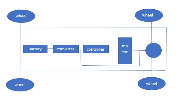
Block diagram:
Powertrain model:
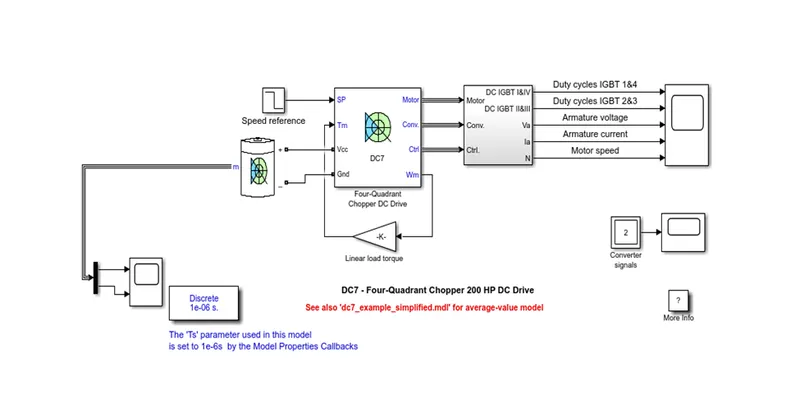
The below model represents the simple powertrain model for aircraft runway. In consists motor controller, battery, motor.
This model consists of battery four quadrant chopper DC drive.
OUTPUT:
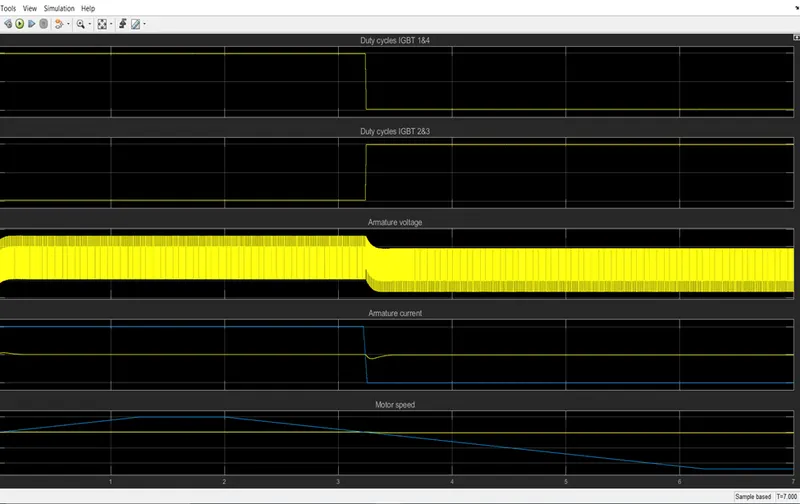
This plot consists of duty cycle of the controller IGBT switches, armature current, armature voltage, motor speed and torque.
(B) Design the parameters in excel sheet.