Project-1: Powertrain for aircraft in runways
Aim : To design Powertrain for aircraft in runways.
Objective 1 : Search and list out the total weight of various types of aircrafts.
Introduction
Aircraft : Any vehicle that is manufactured and made to fly in the air is called an aircraft. An aircraft is a vehicle that is able to fly by gaining support from the air. It counters the force of gravity by using either static lift or by using dynamic lift of an airfoil, or in a few cases the downward trust from the jet engines. Common examples for aircraft include airplanes, helicopters, airships, leaders etc.
Classifications Of Aircraft:
There are two types of classifications for aircrafts. One is lighter than air aircrafts, known as aerostats, and the other is heavier than air aircrafts, called aerodynes.
Aerostats (Lighter Than Air): Aerostats or lighter than air aircrafts are very more lightweight in weight. These types of light aircraft generally use buoyancy like ships, which helps them float in the air. Low-density gas such as hydrogen, helium, or hot air balloons is used to fill in the aircraft. This low-density gas is lighter than air, hence the name. The most common types of aerostats known to us are hot air balloons and sky lanterns.
Aerodynes (Heavier Than Air): Alternatively, the other aircraft, heavier than air or aerodynes, as we understand, is much higher in weight and size. They push the gas or air downwards, which reaction helps to make aircraft upwards. Since these are dynamic through movements in the air, they are called aerodynes. This dynamic lift through the air can be caused mostly through mechanisms, as you must have already known.
- One is the fixed-wing classification, just like planes. In this category of fixed-wing aircraft, the entire mechanism is relied upon forwarding speed to create airflow all over the wings.
- Another mechanism is rotorcraft, which uses spinning rotors that are like wings. The helicopter is the most commonly known aircraft under this classification.
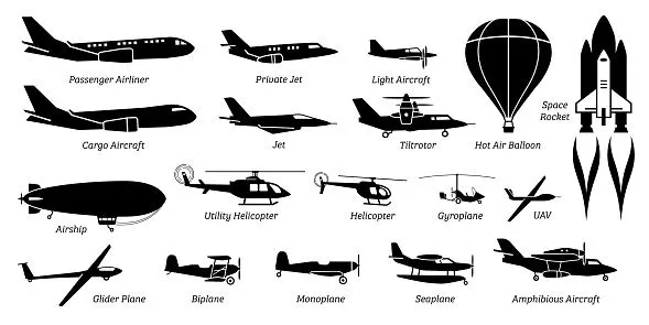
Types Of Aircrafts In The World:
The aircraft gross weight (also known as all up weight an abbreviated AUW) is the total aircraft weight at any moment during the flight or ground operation. An aircraft's gross weight will decrease during a flight due to fuel and oil consumption. And aircraft's gross weight may also very during a flight due to payload dropping or in flight refuelling.
The weights are classified as following :
Maximum Design Taxi Weight (MDTW) : The maximum design taxi weight (also known as the maximum design ramp weight(MDRW)) is the maximum weight certified for aircraft maneuvering on the ground (taxing or towing) as limited by aircraft strength and airworthiness requirements.
Maximum Design Takeoff Weight (MDT0W) : It is the maximum certified design weight when the brakes are released for takeoff and is the greatest weight for which compliance with the relevant structural and engineering requirements has been demonstrated by the manufacturer.
Maximum Design Landing Weight (MDLW) : the maximum certified design weight at which the aircraft meets the appropriate landing certification requirements. It generally depends on the landing gear strength or the landing impact loads on certain parts of the wing structure. The maximum landing weight is typically designed for 10 feet per second (600 feet per minute) sink rate at touchdown with no structural damage.
Maximum Design Zero Fuel Weight (MDZFW) : The maximum certified design weight of the aircraft less all usable fuel and other specified usable agents (engine injection fluid, and the other consumable propulsion agents). It is the maximum weight permited before usable fuel and other specified usable fluids or loaded in specified section of the aeroplane. The MDZFW is limited by strength and airworthiness requirements. At this weight, the subsequent addition of fuel will not result in aircraft design strength be exceeded.
Maufacturer's Empty Weight (MEW) : It is the weight of the aircraft "as built" and includes the weight of structure, power plant, furnishing, installation, systems and the other equipment that are considered an integral part of an aircraft this excludes any baggages, passengers, or usable fuel.
Payload : It is the carrying capacity of an aircraft. It includes cargo, people, extra fuel. In the case of a commercial airliner, it may refer only the revenue-generating cargo or paying passengers.
Operating Empty Weight (OEW) : It is the basic weight of an aircraft including the crew, are fluids necessary for operations such as engine oil, engine coolant, water, unusable fuel and all operator items and equipment required for flight but excluding usable fluids and the payload.
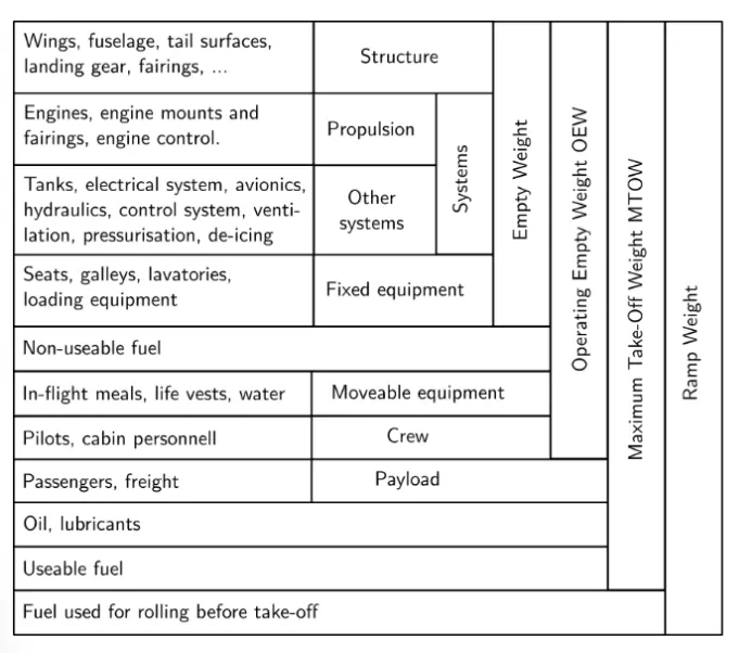
- Basic Empty Weight (BEW) is the weight of the aircraft "as built" and includes the weight of the structure, power plant, furnishings, installations, systems and other equipment that are considered an integral part of an aircraft before additional operator items are added for operation.
- Dry Operating Wieght (DOW) BEW + Weight of Crew (Pilot + Cabin including their bags) + Pantry
- Operating Weight (OW) DOW + Takeoff fuel (i.e. Ramp Fuel - Taxi fuel)
- Maximum Zero Fuel Weight (MZFW) DOW + Payload (anything put on the aircraft that generates revenue to the company, e.g. passenger, baggage, cargo, mail and fret)
- Maximum Taxi Weight (MTW) MZFW + Ramp fuel
- Maximum Takeoff Weight (MTOW) MZFW + Takeoff fuel, or MTW - Taxi fuel
- Maximum Landing Weight (MLW) MTOW - Trip Fuel
The total weights of various types of aircraft are shown below:
MTOW = Maximum take-off weight, MLW = Maximum landing weight, TOR = Take-off run (SL, ISA+15°, MTOW), LR = Landing run (SL, ISA+15°, MLW)
| Type | MTOW [kg] | MLW [tonnes] | TOR [m] | LR [m] | ICAO category | FAA category |
|---|---|---|---|---|---|---|
| Antonov An-225 | 640,000 | 591.7 | 3500 | Heavy | Super | |
| Boeing 747-8F | 447,700 | 346.091 | 3100 | 1800 | Heavy | Heavy |
| Antonov An-124-100M | 405,060 | 330 | 2520 | 900 | Heavy | Heavy |
| Boeing 747-400 | 396,900 | 295.742 | 3018 | 2179 | Heavy | Heavy |
| Boeing 777-200ER | 297,550 | 213.00 | 3380 | 1550 | Heavy | Heavy |
| Concorde | 185,000 | 111.1 | 3440 | 2220 | Heavy | Heavy |
| Vickers VC10 | 152,000 | 151.9 | Heavy | Heavy | ||
| Douglas DC-8-51 | 125,000 | Medium | Large | |||
| Boeing 757-300 | 124,000 | 101.6 | 2550 | 1750 | Medium | Large |
| Boeing 757-200 | 116,000 | 89.9 | 2347 | 1555 | Medium | Large |
| Bombardier CRJ200 | 23,000 | 21.319 | 1918 | 1479 | Medium | Large |
| Embraer ERJ 145 | 22,000 | 19.3 | 2270 | 1380 | Medium | Large |
| ATR 42-500 | 18,600 | 18.3 | 1165 | 1126 | Medium | Small |
| Saab 340 | 13,150 | 12.930 | 1300 | 1030 | Medium | Small |
| BAe Jetstream 41 | 10,890 | 10.570 | 1493 | 826 | Medium | Small |
| de Havilland Hercules | 7,000 | Medium | Small | |||
| Embraer Phenom 100 | 4,800 | 4.43 | 975 | 741 | Light | Small |
Objective 2 : Is there any difference between ground speed and air speed?
Soln:
There are two different types of speed when talking about airplanes – ground speed and airspeed.
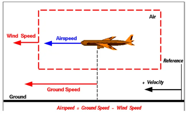
Ground speed is the airplane’s speed relative to the surface of the Earth, Air speed – at least true airspeed – is its speed relative to the air it is flying in.
Wind Speed : It can be defined as the speed at which air moves relative to a fixed reference point on the ground. The wind speed is a vector quantity and has both magnitude and direction. A 20-mph wind from the east is different from a 20-mph wind from the west. The wind has components in all three primary directions i,e.. north-south, east-west and up-down.
In the above figure, we are considering only velocities along the aircrafts flight path. A positive velocity is defined to be in the direction of aircrafts motions. We are neglecting cross winds, which occur perpendicular to flight path but parallel to the ground, and updrafts and downdrafts, which occur perpendicular to the ground.
Ground speed : It is the aircraft’s speed relative to the ground. ground speed is what determines how fast an aircraft will get to its destination. Ground speed is also a vector quantity so a comparison to the ground speed to the wind speed must be done according to rules for vector comparisons.
One thing that should be noted here is that it’s its horizontal rather than vertical speed – an aircraft climbing completely vertically would have a ground speed of zero.
Air speed : It is the aircraft’s speed relative to the air it is flying in. It determines whether there is enough airflow around an aircraft to make it fly. Airspeed cannot be directly measured from the ground position, but must be computed from the ground speed and the wind speed. Airspeed is a vector difference between the groundspeed and the wind speed.
Air Speed = Ground speed - wind speed
There are 3 types of air speed :
Indicated air speed :- it is an air speed that is calculated directly off from an aircraft pilot static system. It is the calculated off from aircraft dynamic pressure - the difference between it's total pressure and static pressure. The dynamic pressure depends not only on the aircraft's speed, but also on the density of the it's flying in. As such the higher the aircraft flies and the lower the air density as a result - the bigger the difference between indicated and true air speed.
Calibrated air speed :- It is indicated air speed adjusted for a variety of errors. Just as an example, one of things it is adjusted for is the flap position. The reason for that is that not different flap positions, air flows differently around the pilot-static system and affects the indicated airspeed readings.
True air speed :- It is actually the speed at which an aircraft is moving relative to the air it is travelling in. It's calibrated air speed adjusted for the exact conditions (altitude, air temperature, etc) that the aircraft is flying in.
To visulaize these speed an animation by NASA is attached below :
https://www.grc.nasa.gov/www/k-12/airplane/Animation/airrel/anrelg.html
Conclusion : Yes, there is a difference between ground speed and air speed. Ground speed is how fast an airplane's shadow would move across the land. If there is a strong wind pushing an aircraft, that's reflected in the ground speed. Airspeed, in contrast is how fast an airplane is really flying strictly under its own power, which is calculated by subtracting the wind speed from the ground speed. On a perfectly still day the air speed is equal to ground speed. But if the wind speed is blowing in the same direction that the aircraft is moving, the air speed will be less than the ground speed.
Objective 3 : Why is it not recommended to use aircraft engine power to move it on the ground at Airport?
Soln:
The risks which may arise from engine ground running relate to the potential for loss of control of the aircraft by those persons occupying the pilot seats in the flight deck. In most cases, such persons will be maintenance personnel holding specific company-issued approval for the required tasks. The consequences of loss of control during taxi or towing are the same as apply to these operations generally and this article is concerned only with the risks arising from the static running of one or more aircraft engines. Unwanted consequences from such static running are mainly related to those arising from the unintended movement of the aircraft during engine running - effectively a loss of control - especially during high power engine running. Damage can occur to the aircraft itself, other aircraft nearby or to airside structures. In addition, there is a risk of injury to ground support personnel who may be in relatively close proximity to the aircraft.
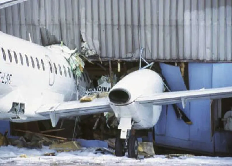
Reasons for not using aircraft engine power to move it on the ground at Airport:-
- Usage of high power mounted engines have high risk of blasting.
- Usage of low power mounted engines have a risk of impurities on the ground may enter inside the engine.
- Huge amount of fuel is consumed by the engine which is again is a disadvantage. So by taxing fuel can be saved for the aircraft's flight.
- Aircraft's engine creates a huge noise around which is not good for surrounding's around the airport.
- It will cause various injuries and damage to the near by population and property if a pilot looses control of the airplane traveling on the ground using engine power.
Objective 4 : How an aircraft is pushed to runway when its ready to take off?
Soln :
The term that is used when the aircraft is moved from the hanger to the runways is "TAXIING" which is defined as the moment of an aircraft on the ground, under its own power, in contrast to towing or pushback where the aircraft is moved b a tug. An airplane uses taxiways to taxi from one place on an airport to another. The term 'taxiing' is not used for accelerating run along a runway prior to take off, or the deaccelerating run immediately after landing, which are called the takeoff and landing rollout respectively.
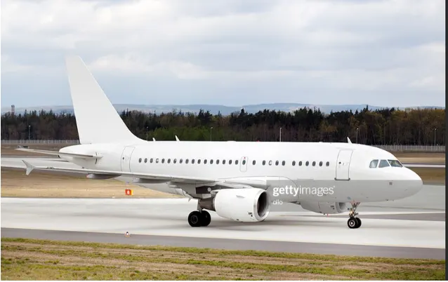
Taxiways, too, can vary in width and loading-bearing strength depending on the airfield. Depending on these factors, they are categorised so that pilots know which taxiways they are able to use for their aircraft type. The taxiways at some airports can be particularly tight especially for bigger aircraft. With a wingspan of more than 60 meters, pilots on the 787 Dreamliner always have to be mindful on their wingtips. Given below image is an airplane taxiing on its own.
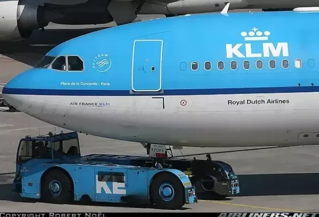
Another way to move the aircraft on the ground that is "TOWING" which is defined as coupling two or more objects together so that they ma be pulled by a designated power sources. The towing source may be a motorized land vehicle, vessel, animal or human and the load being anything that can be pulled. These may be joined by a chain, rope, bar, hitch, three-point, fifth-wheel, coupling, drawbar, integrated platform, or other means of keeping the objects together while in motion.
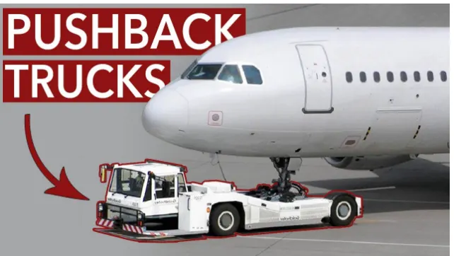
A pushback truck lifts the front wheel of the aircraft, thier role in most airports is to move the aircraft away from the parking spot on to the taxiways. Here the truck is removed and when all platform staff is out of the way the engines are started one by one. From here on the aircraft moves on its own power to the runway. In the aircraft you will hear the engine spinning up when power is demanded for accleeration.
Objective 5 : Learn about take off power, tyre design, rolling resistance, tyre pressure, brake forces when landing.
Soln :
1) Take off Power : Take off is a phase of flight in which an aerospace vehicle leaves the ground and becomes airborne. For aircraft travelling vertically, this is known as liftoff. For aircraft that takes= off horizontally, this usually involves starting with a transition from moving along the ground on a runway .
For light aircraft, usually full power is used during take off. Large transport category (airline) aircraft may use a reduced power for take off, where less than full power is applied in order to prolong engines life, reduce maintenance costs and reduce noise emissions. In some emergency cases, the power used can then be increased to increase the aircraft's performance. Before take off, the engines particular piston engine are routinely run up at high power to check for engine-related problems.

Take a performance can be predicted by using a simple measure of acceleration of the aircraft among the runway based on force equilibrium. Wings keep an airplane up in the air, but the forces are what make this happen. They push a plane up, down, forward, or slow it down.
The force involved will be:
Thrust : it is the force generated by the engine of aircraft to move it through the air. To maintain level flight at constant speed, constant thrust is required. To climb or decend the aircraft whilst maintaining the constant speed, the thrust must be increased or decreased.; To increase or reduce the speed of the aircraft whilst maintaining level flight, the thrust must be increased or decreased. That is air is pulled in and then pushed out in opposite direction.
T = (Pshaft .η )/V
Drag : it is the force that acts opposite to the direction of motion. It tends to slow an object. Drag is caused by friction and differences in air pressure. So in aircraft the force that acts opposite to thrust is called drag. An example is putting your hand out of a moving car window and feeling it pull back.
D = Cd . 0.5 .ρ.V2.S
Weight : The force that acts due to gravity. It includes the total weight of the aircraft.
W =mg
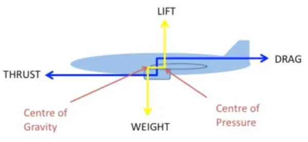
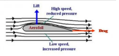
Lift : A flow past an airplane exerts a force on the surface. The component of this force perpendicular to the air flow is called lift. The airflow over the wing increases its speed causing a reduction in pressure; This generates a force (lift) perpendicular to the cord of the aerofoil. The airflow below the wing moves much more slowly generating greater pressure and less or negative lift.
Total power will be the addition of all the forces.
Total force = Thrust + weight + Drag + Lift + rolling resistance
Power required = Total force * Velocity of aircraft
2) Tyre Design : An aircraft tyre is designed to withstand extremely heavy loads while landing, take off, taxing and parking. The number of wheels required for aircraft increases with the weight of the aircraft as the weight of the aeroplane needs to be distributed more evenly.
Engineers are challenged with designing tires with cool running, heat-resistance material while simultaneously exceeding tyre service requirements. Tyre prototypes are put through rigorous tests that simulates cycles of landing, take-offs and taxi operations. It is only after the tire pass all mandatory tests and meet the requirements of the aircraft manufacturer and airworthiness authorities that the tyres are put into the production.
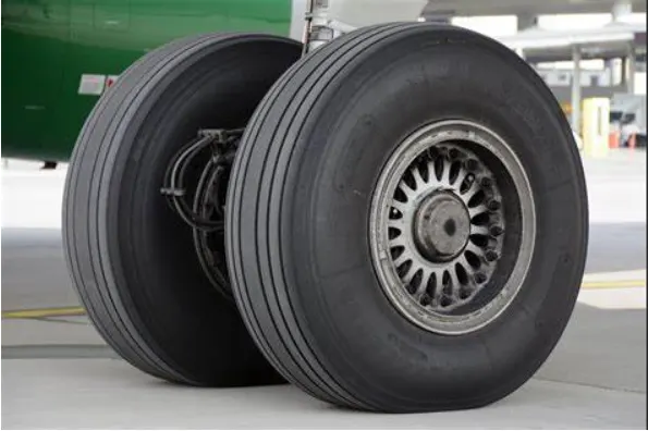
Two types of tyres are used in aircraft application, and those are bias-ply tyre and radial tyre.
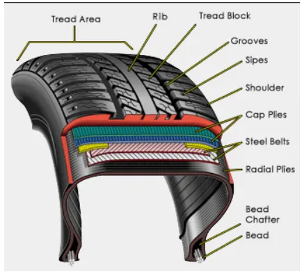
i)Bias-ply tyre : Bias ply tyres or popular choice for aircraft tires because of their durability and retreadability. The tyre construction consists of the following components: the cross section of bias tires is shown below:

Tread : The tread is made up of rubber mixed with other additives to obtain the desired level of toughness, durability and resistance of wear.
Sidewall: The sidewall is a protective layer of the rubber that covers the outer casing ply. It extends from the tread edge to the bead area.
Buff Line Cushion: The buff line cushion is made up of rubber component to enhance the adhesion between tread reinforcing ply and the breakers or casing piles.
Breakers : Breakers are reinforcing piles of rubber coated fabric placed under the buff line cushion to protect the casing piles and strengthen stabilize the tread area
Casing Piles : Alternate layers of rubber-coated fabric (running at opposite angles to another) provide the strength of that tire.
ii) Radial tyre : A typical radial tyre with their rigid belt, they provide increased landings and reduced rolling resistance. They have fewer components in their construction and are lighter than similarly sized bias ply tyres. Components that differ from bias-ply construction are as follows:
Overlays : A layer of reinforcing rubber coated fabric placed on top of the belts to aid in high speed operation.
Belt Plies : A composite structure that stiffens the tread area for increased landings. The belt plies increases the tire strength in that tread area.
Casing plies : As in bias-ply tires, the casing plies are layers of rubber-coated fabric. However , unlike those in bias plies that run at opposite angles to one another, the radial plies run radially from bead to bead.
Chippers : The chippers or layers of rubber coated fabric applied at diagonal angles that improves the durability of the tire in the bead area.
3) Rolling Resistance : Rolling resistance sometimes called rolling friction or rolling drag, is the force resisting the motion when a body (such as ball, tyre, wheel) rolls on the surface. It is mainly caused by non elastic effects; That is, not all the energy needed for deformation of the wheel,roadbed etc., is recovered when the pressure is removed. Another cause of rolling resistance lies in the slippage between the wheel and the surface, which dissipates energy.
In aircraft the friction between aircraft and runway will be proportional to the normal force exerted by the aircraft on the runway. So rolling resistance force is given by
F = crr*(W-L)
The normal force will be the difference between weight of aircraft and lift, the friction coefficient or the coefficient of rolling resistance(crr) will be typically of a magnitude of 0.02 for a standard tarmac runway.
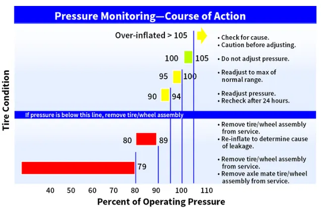
4) Tyre Pressure : Aircraft tyres operates at such high extremes of pressures, load and speed, their care and service is critically important. The most important action an operator can take to prevent tyre related events is to maintain proper tire inflation pressure. Failure to keep aircraft tires properly inflated can lead to very serious consequences. One relatively easy way to help avoid those consequences is to check tyre pressures regularly and service them as necessary.
Following this 3 actions is a good way to make sure you get the most value out for your tires and contribute the safe operation of your aircraft:
- Perform daily pressure checks with a calibrated gauge.
- Target the highest pressure recommanded in the AMM or POH.(105 percent of operating pressure).
- Compensate for ambient temperature changes.
6) Brake Forces When Landing : Aircraft brakes stop a moving aircraft by converting its kinetic energy to heat energy by means of friction between the rotating and stationary discs located in brake assembles in the wheels. Brakes provide this critical stopping function during the landing to enable airplanes to stop within the length of the runway. They also stop aircraft during rejected take-off events, in which an attempted take off is cancelled as the airplane is rolling down the runway before it lifts-off from the ground due to engine failure, tire blowout, other system files or direction from air traffic control.
Aircraft brakes also prevent motion of the aircraft when it is parked, limit its speed during taxing and can even help steer the aircraft on the ground by applying different levels of braking force to the left and the right side brakes.
The touchdown velocity should be approximately the stall speed of the aircraft in landing configuration. This will be achieved by increasing the drag and deaccelerate the aircraft to minimum flying speed. The deacceleration on the landing roll will be accomplished by the braking and reverse thrust.
The braking force required will be calculated by the following equation,
dv/dt = - {(T+F+D)/m}
here, T - is the thrust
D - is the aerodynamic drag force
F - is the rolling resistance force
m - is the mass of the aircraft
and -(dv/dt) - will be the decelartion
so the brake force required will be mass*deceleartion
Part B:
6. A. With necessary assumptions, calculate the force and power required to push / pull an aircraft by a towing vehicle.
Soln :
The force required to push/pull an aircraft by to towing are Rolling resistance force and Aerodynamic drag force.
1) Rolling resistance force :Rolling resistance sometimes called rolling friction or rolling drag, is the force resisting the motion when a body (such as ball, tyre, wheel) rolls on the surface. It is mainly caused by non elastic effects; That is, not all the energy needed for deformation of the wheel,roadbed etc., is recovered when the pressure is removed. Another cause of rolling resistance lies in the slippage between the wheel and the surface, which dissipates energy.
The magitude of Rolling resistance force is given by Fr = crr*m*g
Where, Crr is the coefficientt of rolling resistance
m - is the total mass of the vehicle( vehicle mass + payload)
g - is the acceleartion due to gravity
2) Aerodynamic drag force : Drag (sometimes called air resistance a type of friction, or fluid resistance another type of friction or fluid friction) is a force acting opposite to the relative motion of any object moving with respect to a surrounding fluid. This can exist between two fluid layers (or surfaces) or a fluid and a solid surface. Unlike other resistive forces, such as dry friction which are nearly independent of velocity, drag force depends on velocity. So basically the drag force will resist motion of an object.
The magnitude of the drag force is given by Fd = 0.5*e*A*Cd*V2
here, e - is the density of air in kg/m3
A - is the frontal area
Cd - is the drag coefficient
V - is the velocity of a vehicle in m/s
Here we are assuming the towing vehicle and craft is moving with a constant speed so acceleartion forces will be 0 and also the hill climbing force is also 0 because the towing vehicle is travelling on flat surface.
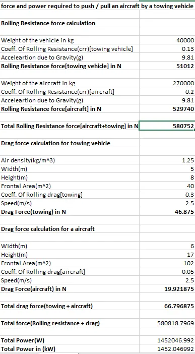
https://docs.google.com/spreadsheets/d/1-HqpVGf0Ex_qfRZtjTzKFmXODzpFDzXg/edit?usp=sharing&ouid=111335005276448861725&rtpof=true&sd=true
Here we have assumed the weight of towing vehicle as 40000kg and we have taken Airbus A350 aircraft which is being towed by the towing vehicle. The weight of the aircraft is 270000 kg.
Speed assumed here is 2.5m/s it will be low because the towing vehicle will not run a high speed while pushing/pulling the aircraft.
Then, rolling resistance force and drag force is calculated for both towing vehicle and aircraft. And both is summed up for the total force. So here the total force is 580818.7969 N or 5808.18 KN
The total power is calculated by multiplying total force and velocity is 1452.046 KW
6.B. Develop the model for the calculated force and power using Simulink.
Soln:
The magitude of Rolling resistance force is given by Fr = crr*m*g
The magnitude of the drag force is given by Fd = 0.5*e*A*Cd*V2
Simulink Model :
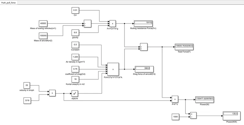
https://drive.google.com/file/d/1RGVPfrIylExuf9g8n5pJu_Xf90E2OsCq/view?usp=sharing
Explaination :-
- To find the value of rolling resistance(Frr) ,values of Crr, total mass(m), gravity(g) are taken in constant block and are multiplied in product block to obtain Frr.
- Similiarly for calculating Drag force(Fd), we have to multiply the velocity in m/sec, Drag coefficient(Cd), Frontal area of aircraft(A) and a constant value 0.5 which are to be entered in 'constant block'.
- In order to convert velocity in kmph to m/sec we have multiplied it with 5/18.
- For calculating the Total force(F) we have add both Frr and Fd blocks by using 'sum block'.
- For calculating power we have to multiply both total force(F) and velocity in m/sec for this we have used 'product block' (P=F*V).
7. A. Design an electric powertrain with type of motor, it’s power rating, and energy requirement to fulfill aircraft towing application in Simulink. Estimate the duty cycle range to control the aircraft speed from zero to highest. Make all required assumptions. Prepare a table of assumed parameters. Draw a block diagram of powertrain.
(Hint :DC7 Block)
Soln :
Power train : The powertrain provides power to vehicle. Powertrain refers to the set of components that generates the power required to move the vehicle and deliver it to the wheels.
An electric powertrain has 60% fewer components than the powertrain of IC engine vehicle. The components that form in electric power train are,
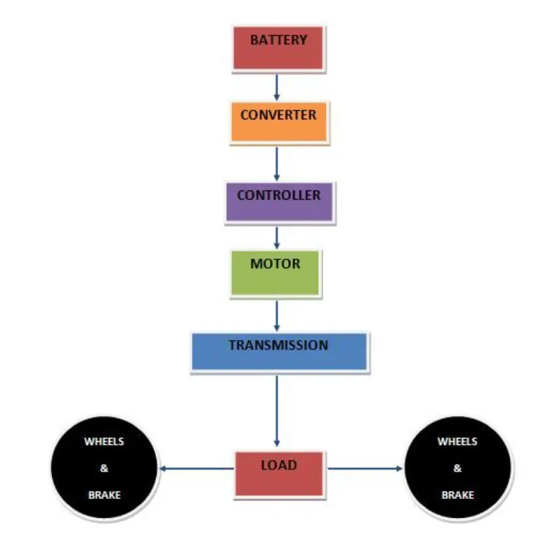
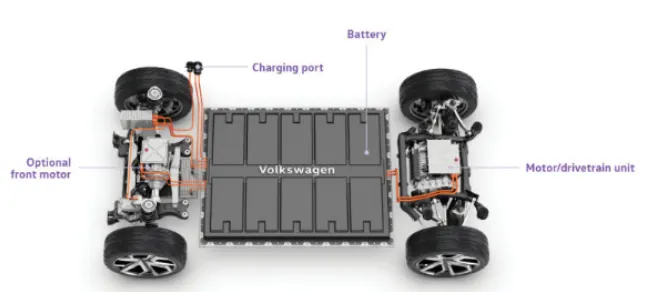
1) Battery : The battery is a component which will give power to the electric motor. The batteries generally used in electrical vehicles are lithium ion type. Battery also stores the energy.
2) Power electronics converter - Power electronics technology deals with processing and controlling the flow of electrical energy in order to supply voltages and currents in a form that optimally suited for end user's requirements. A power electronics converters uses power electronic components such as SCRs,TRIACS,IGBTs etc, to control and convert the electric power. The main aim of converter is to produce conditioning power with respect to a certain application.
The types of power converters used in electric vehicles are:
- AC to DC converter - Converts AC input signal into DC.
- DC to DC converter - Converts DC input signal into DC. Also called DC chopper because the output we get here is chopped.
- DC to AC converter - Converts DC input signal into AC.
3) Electric motor : The electric motor converts electrical energy into mechanical that is delivered to the wheels via transmission system.
4) Transmission system: Transmission system is a system consisting of gears which will transmit the power to the wheels.
5)Motor controller : Motor controller is used to control the output of the motor as per the drivers requirements.
Simulink model for powertrain :-
Parameters :
- Battery
- DC motor
- Gear box
- Wheel and Axle
- Mass
- Ideal torque sensor
- PS-simulink converter
- Display
- Solver configuration
- Electrical and rotational references
Explanation :
To fullfil the towing application main elements is torque, so if the motor towing vehicle produce required amount of torque in push/pull the aircraft then and only it can fulfill towing application.
To prove that let us assume the above values power and force of the following vehicle to push/pull of aircraft.
Let us assume,
- Force = 3145N
- Power = 9.4kW
W.K.T torque , T = F*r/G
radius of the tyre = 0.67m
gear ratio =10
T = 3145*0.67/10 = 210Nm
Thus its required 210Nm to fulfill the following application.
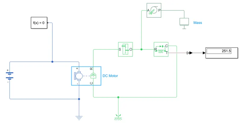
https://drive.google.com/file/d/1NKO1MszK-U2As_jn1PnE7eq99GTEtXoV/view?usp=sharing
In this DC motor is user, you can use induction motor to but for simple operation DC motor is the best. Ideal torque sensor is used to know the torque produced by the motor. Display is connected to view the values of torque.
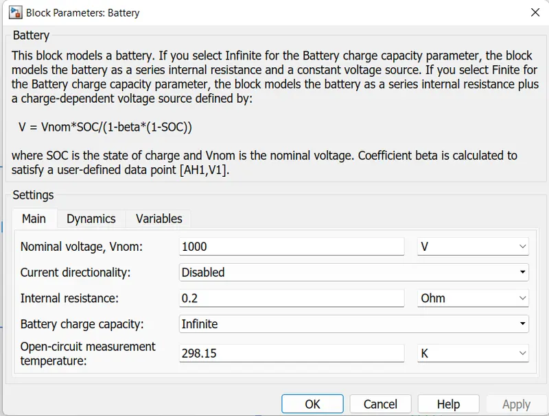
Changing the battery voltage 2000 Volt as shown in the figure.
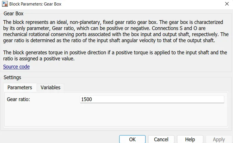
To the towing vehicle additional gear box is required in order to get the highest torque.
W.K.T highest torque is obtained at least speed, so change the gear ratio to 1500
Results :
Run the model, thus 251.Nm torque is produced by the motor so the electric motor can fulfill towing application with highest value of voltage(v=1000) and highest gear ratio(G=1500).
Energy = power * time
= 9.4*60*60
= 33840 J
= 33.84 KJ
Thus 10KW(~9.4KW) power rating and 33.84KJ energy requirement is must for the electric motor to fulfill towing application.
Duty cycle calculation
- Rated power = 10KW
- efficiency = 90%
The motor output power is the input power of th tugs tractor so to obtain maximum speed the duty cycle needed is calculated as,
Duty cycle = output power/input power
Motor input power = rated motor power /Motor efficiency
= 10/0.9
= 11.2
power required to aircraft is 9.4 KW
duty cycle = 9.4/11.2 = 0.839
Thus the duty cycle range to control the aircraft speed from zero to highest is 83%.
Assumed parameters in tabular form
Parameters values
- Rolling resistance co-efficient of truck Urr1=0.006
- Rolling resistance co-efficient of aircraft Urr2=0.001
- Mass of the truck m1=40000kgs
- Mass of the aircraft m2=80000kgs
- Gravitional force constant g=9.8/s^2
- Air density p=10255 kg/m^3
- Drag coefficient of truck Cd1=0.8
- Drag coefficient of aircraft Cd2=0.05
- Frontal area of truck and aircraft A1=5 and A2= 20m^2
- Velocity of truck = Velocity of aircraft v= 3m/s
7.B. Also, Design the parameters in excel sheet.
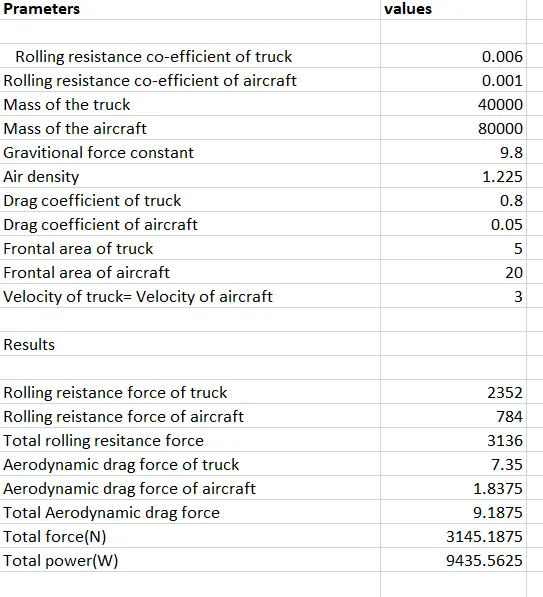
https://docs.google.com/spreadsheets/d/1Q3fFR0SZoDRSrRXAjl1MYz2dyk-6432F/edit?usp=sharing&ouid=111335005276448861725&rtpof=true&sd=true