Project-1: Powertrain for aircraft in runways
*#*#*#*#*#*#*#*#*#*#*#*#*#*#*#*#*Part-A*#*#*#*#*#*#*#*#*#*#*#*#*#*#*#*#*#*#*#*#*#
1. There are 6 categories based on weights as per the FAA of USA.
| Category | Criterion | Example |
| 1-Heavy | Any aircraft weighing more than 255,000Ibs | Boeing 747, Airbus A340 |
| 2-B-757 | Boeing 757 all series Boeing |
Boeing 757 all series |
| 3-Large jet | Large jet aircraft weighing more than 41000, and up to 255000 Ibs. | Boeing757, AirbusA320 |
| 4-Large computer jets |
Large non-jet aircraft.Small regional jets from 41000 to 255,000 Ibs |
Aerospatiele/Alenia ATR42 and the Saab SF-340 for large non-jet, Bombardier Canadair regional jet |
| 5-Medium | Small commuter aircraft including business jets weighing more than 12,500 or up to 41000 Ibs | Embraer 120, Learjet-35 |
| 6-Small | Small, single or twin-engine aircraft, weighing 12500 or less | Beech 90 or Cessna Caravan |
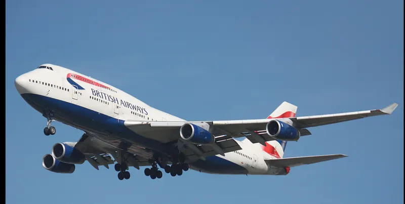
Fig-AirbusA340(Heavy category)
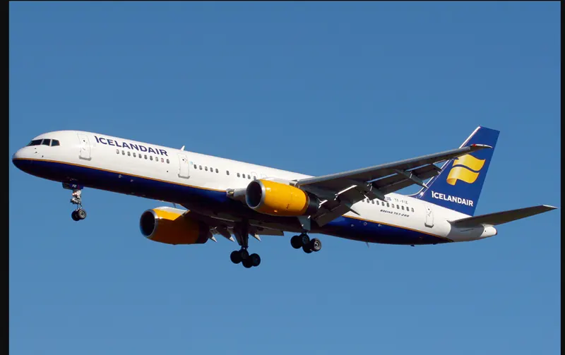
Fig-Boeing757 (Large Jet)
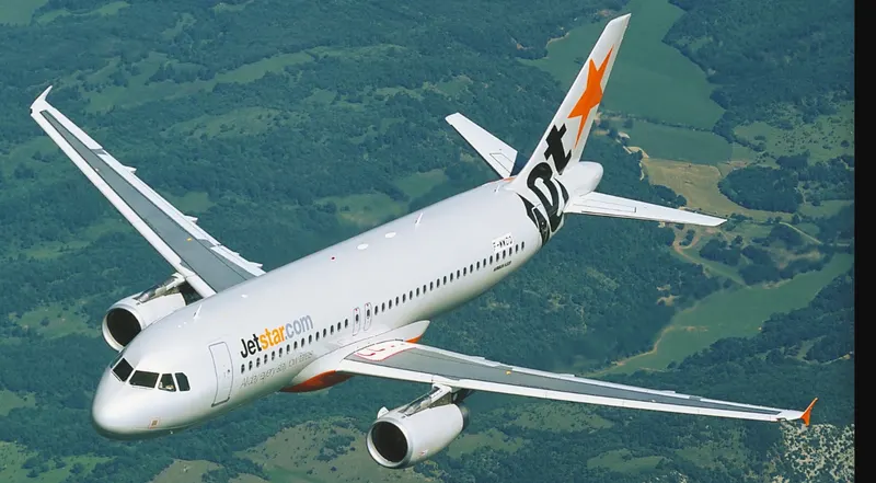
Fig-AirbusA320(Large jet)
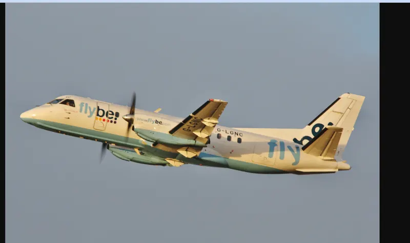
FIG-saabSF340(Large Non Jet aircraft)
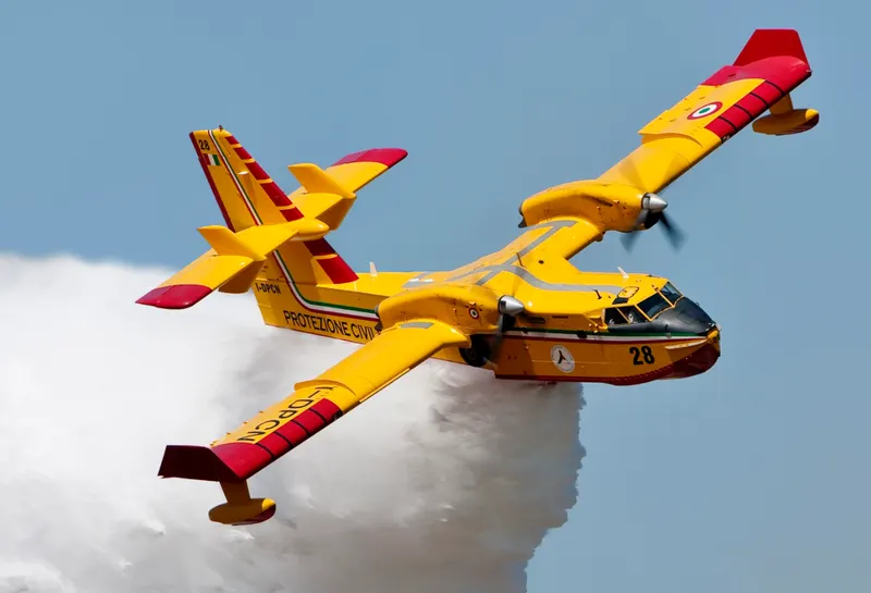
Fig-Bombardier Canadier(Regional Jet)
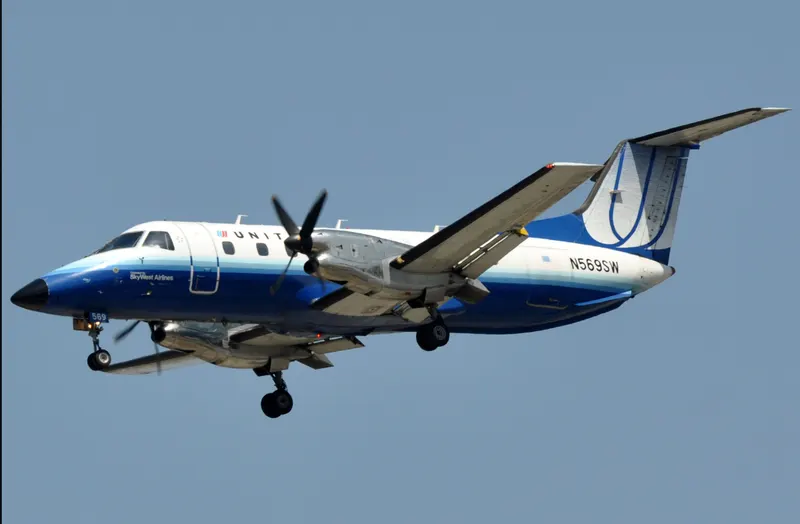
FIG-Embraer120
Unknown refers to unspecified equipment.
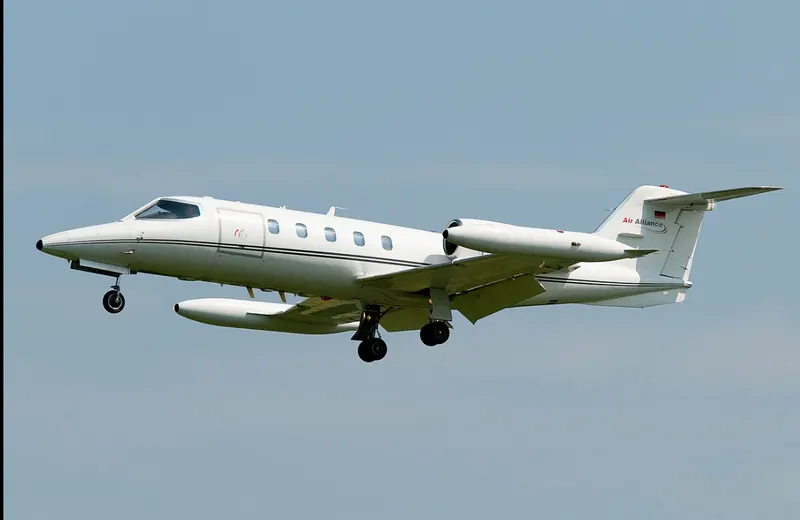
Fig-Learjet35
Learjet 35[edit]
The original Model 35 was powered by two TFE731-2-2A engines and was 13 inches longer than its predecessor, the Model 25. The first flight of the prototype Model 35 was on 22 August 1973, and the aircraft was FAA-certified certified in July, 1974. It could carry up to eight passengers. There were 64 base-model 35s built.[4]
Learjet 35A[edit]
The Model 35A is an upgraded Model 35 with TFE731-2-2B engines and a range of 2,789 miles, with a fuel capacity of 931 US gallons (3,524 L) with refueling accomplished at ground level through each wingtip tank. It was introduced in 1976, replacing the 35. Over 600 35As were built, with a production line that ended with serial number 677, in 1993.[4]
Source-https://en.wikipedia.org/wiki/Learjet_35
On February 12, 1996, a Learjet 35A, N10BD,[6] owned by Cable Television Founder Bill Daniels and piloted by Mark E. Calkins, Charles Conrad, Jr., Paul Thayer, and D. Miller completed an around-the-world flight in a record 49 hrs, 21 min, and 8 sec. The record remains standing as of 2015.[7] This aircraft is now on display in Terminal C of Denver International Airport.[8]
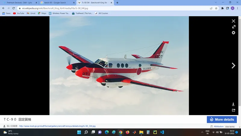
Fig-Beech90
Source- FAA(Federal Aviation Administration)
Q:2: Difference between Ground speed and airspeed:
- Ground speed is the horizontal speed of an aircraft relative to the surface of the earth.
- It is vital for the navigation that the pilot has an estimate of the ground speed that will be achieved during each leg of the flight.
- An aircraft diving vertically would have a ground speed of zero. The information displayed to passengers through the entertainment system of the airline, aircraft usually gives ground speed rather than airspeed.
- Groundspeed can be determined by the vector sum of the aircraft's true airspeed and the current wind speed and direction.
- A headwind Substracts from the ground speed, while a tailwind adds to it. Winds at other angles to the heading will have a headwind or tailwind components.
- An airspeed indicator indicates the aircraft's speed relative to the air mass. The air mass may be moving over the ground due to wind ,and therefore some additional means to provide position over the ground is required. This might be through navigation using landmarks,
- ground speed is how fast an airplane is traveling, relative to a fixed point on the ground. Think of it this way: Ground speed is how fast an airplane's shadow would move across the land. If there's a strong wind pushing an aircraft, that's reflected in the ground speed.
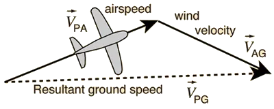
-
Airspeed, in contrast, is how fast an airplane is really flying strictly under its own power, which is calculated by subtracting the wind speed from the ground speed. NASA explains:
On a perfectly still day, the airspeed is equal to the ground speed. But if the wind is blowing in the same direction that the aircraft is moving, the airspeed will be less than the ground speed.Airspeed doesn't just affect airplanes. It also affects our vehicles on the ground. As this study published in 2013 in the International Journal of Energy and Environmental Engineering describes, a car's airspeed on the highway is what really determines its fuel efficiency, rather than ground speed or the speedometer reading.
-
Back in February 2019, a Virgin Atlantic Boeing 787 jet flying over Pennsylvania in route from Los Angeles to London reached what might seem like an amazing speed of 801 miles per hour (1,289 kilometers per hour), according to CBS News.
But the speed record wasn't because that Virgin Atlantic aircraft itself was exceptionally fast. Like a sprinter running with the wind at his back, the aircraft benefited from an exceptionally fast jet stream, a high-speed wind moving at 231 miles per hour (371.7 kilometers per hour). It was the fastest jet stream in more than 60 years.
As CBS News explained, the result was that the 787 flew considerably faster than the aircraft's typical cruising speed of 561 miles per hour (902.8 kilometers per hour).
Therein lies the difference between airspeed and ground speed.
https://science.howstuffworks.com/transport/flight/modern/airspeed-vs-groundspeed.htm
---------------------------------------------------------------------------------------------------------------------------------------------
Q-3:
Parking a 200-Ton Airliner: How Pilots Move a Plane Around on the Ground
Large international airports can be massive places. Denver, Colorado’s main airport, for example, takes up an area of 53 square miles. By comparison, the area of Manhattan is 34 square miles, San Francisco is 47 square miles and Miami is 36 square miles. At some airports like Amsterdam, once you’ve landed you can still have several miles left to taxi until you reach the terminal building. Conversely, some busy airports are so restricted for space that it poses real issues for aircraft getting around on the ground. New York’s JFK is a prime example of this.
How Aircraft Move
Most Aircraft Can’t Reverse
When you arrive at the gate for your flight, more often than not you’ll get a great view of the nose of the aircraft through the terminal window. If you look closely, you’ll be able to see us pilots preparing the aircraft for departure. Funny enough, we can see you peering out at us too, so if we wave, don’t be embarrassed to wave back.
However, the obvious problem with parking facing the terminal is that in order to get to the runway, we need to move backward off the stand first. If this was on your drive at home, you’d just pop your car into reverse, back out onto the street and off you go. Unfortunately, aircraft are unable to do this as they don’t have a reverse gear. In order to get round this problem, we use the assistance of a pushback tug.
Pushback Tugs: The Little Engines That Could
For smaller aircraft, the pushback tug doesn’t require a massive amount of power. They utilize the weight of the tug, sometimes up to 60 tons, to ensure that the wheels don’t just spin on the tarmac. “The small ones have enough power to push and tow an aircraft up to a 757,” says Airside MUC, a pushback driver at Munich International Airport. “The functionality is pretty simple. We connect a tow-bar at the aircraft first, then at the tug.”
It takes skill to push an aircraft back using these types of tug. “You have two steering axis here at the nose gear and at the tug where the tow-bar is connected,” he said. “So when you steer right, the nose of the aircraft goes opposite.”
However, with bigger aircraft, tug designers ran into a problem. Even with a 60-ton tug, there isn’t enough weight to stop the tug wheels spinning. To get round this problem, they needed something to weigh the tug down. Something like the weight of a 560-ton A380.
Tow-barless tugs clamp around the nose wheel of the aircraft and lift it up, thus utilizing the weight of the aircraft to provide the traction for its wheels. “We need between 40 and 90 seconds to connect the tug with the aircraft and lift it up,” he added. “The Goldhofer AST-1X is the Godfather of all tugs because at 32 tons, its 16-liter 700 HP engine is enough to push all heavies easily. We use that tug for 767 up to A380.”
Steering System
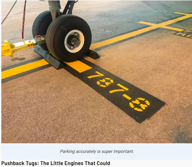
Once moving, pilots need to be able to steer the aircraft around corners. With a wingspan of 60.1 meters, the 787-8 is wider than it is long. The pilot’s eye level is 5.5 meters above the ground, and this creates a 14-meter blind spot ahead of the aircraft. So, accurate taxiing is essential.
This is done through two different sets of controls. Limited steering is possible using the rudder pedals, which sit underneath the pilot’s feet. Unlike in your car, the pedals under our feet have very little to do with acceleration and a lot to do with braking and steering. These primarily control the rudder on the tail (mainly used in crosswind landings) and also control the brakes. However, the main source of steering comes from the nosewheel steering tiller, which can turn the nose wheel up to 70 degrees.
The Braking System
Brakes on the Main Wheels
Getting moving is no good unless you can bring the aircraft safely to a stop. To do this, each wheel on the main landing gear has a brake unit. On most aircraft, the brakes are powered by the hydraulics system. However, on the 787 Dreamliner, which I fly, the eight main wheel brakes are electrically powered instead. This means that the aircraft then produces fewer CO2 emissions due to the lower weight — 111 kilograms for each 787-9 aircraft. The simplified system also benefits engineers as the procedure to replace a brake unit is much quicker and easier.
Being such a safety critical part of the aircraft, the braking system has to work well under all conditions. This includes situations where a brake unit isn’t working. During the testing stage of the aircraft, engineers put them through a punishing process as can be seen in the video below.
It’s from this and further testing that it was determined that a Dreamliner could safely stop even with two of the eight braking units not working. The braking system also has two further features: Antiskid Protection and Autobrake. The autobrake system provides automatic braking at a deceleration rate selected by the pilots. For every landing, pilots calculate how much runway they will require depending on their weight and weather conditions. They can then select a level of autobrake to have them slowed safely to exit the runway. As soon as the aircraft touches down, the aircraft evenly applies the required braking pressure across all of the brakes. This results in smoother deceleration of the aircraft and makes it much more comfortable for passengers.
However, when landing at 190 tons on a slippery runway in the middle of winter, the last thing you want is for your wheels to start skidding. To protect against this, most airliners have an Antiskid Protection system. Each wheel has a wheel speed sensor, which, when it detects a skid, reduces the braking force until the skid is no longer detected. This ensures maximum braking efficiency is achieved, even in the most challenging of conditions.
Parking
You may have flown thousands of miles, but the last few meters of the flight can often be the most challenging. The parking stand is a super busy place, so the pilots need to ensure that they stop the aircraft in exactly the correct spot. Too short or too far and the air bridge may not reach the door. Too far left or right and they risk clipping the wingtip of the aircraft parked next door. When it comes to this level of precision, what better to trust than the accuracy of lasers.

Laser-Guided Docking Systems
At the front of each parking stand is a docking system. Using 3-D scanning techniques, the system cannot only recognize the type of aircraft, but also detect any obstructions on the stand. As the aircraft approaches the stand, the system provides the pilots with directions to keep them lined up with the center of the stand and also the distance left to the stop mark.
Should an obstruction, such as a rogue vehicle, be detected on the stand as the aircraft approaches, the display will issue the pilots with a command to stop. This is why it’s important that you keep your seat belt fastened until the signs are turned off.
source - https://thepointsguy.com/guide/how-pilots-move-a-plane-around-on-the-ground/.
---------------------------------------------------------------------------------------------------------------------------------------------
Q:4-
Aircraft Pushback Tractor Purpose
The most common operation for which a pushback tractor is used is an aircraft pushback operation. After an aircraft lands on the runway, it finally reaches an aircraft stand (also called an aircraft bay or airport gate) where it finally stops. This is where the passengers deplane the aircraft.
Airline crew and ground handling agencies perform different servicing tasks on the aircraft at the bay to make it ready for the next operation. We have made a dedicated post to explain the different types of ground handling and support activities that take place at an aircraft stand.
After all servicing activities are finished, aircraft needs to get back on the runway to take off, however, it first needs to reverse itself from the aircraft stand. This is where the pushback tractor comes in.
A towing hook attaches its one end to the aircraft and the other end to the pushback tractor. The driver receives a go ahead signal from Pilot and begins the pushback operation.
It pushes the aircraft back and also steers it so that the aircraft ends up in correct position on the taxiway (a connecting pathway between aircraft stand and runway).
Pilot then gives an okay to disengage signal to the pushback tractor driver at which he unhooks the towing bar and steers the pushback tractor away from the aircraft.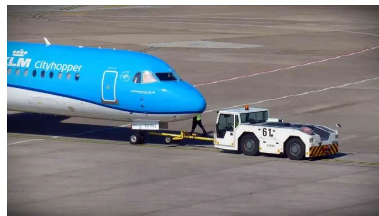
A Conventional Pushback Tractor pushing back an aircraft
Other Uses of Aircraft Pushback Tractor
Although, pushback from the bay is the most common use of aircraft pushback tractors, it is not the only use. They used for movement of aircrafts in other scenarios as well. Let us discuss these scenarios one by one.
Maintenance Hangar Movement
A maintenance hangar is a large facility where different maintenance activities are performed on an aircraft. These hangars are located on airports and maintained by airline and ground handling staff.
Aircrafts don’t enter and leave the maintenance hangar with their engines on. It is because hangar is an enclosed space and it is not safe for aircrafts to enter and leave this space with jet engines on.
In fact, jet engines are not turned on inside maintenance hangars as an standard operating procedure as there is also a great risk of FOD (foreign object debris) such as a tool getting ingested into the engine.
In view of above, pushback tractor is used to bring an aircraft inside the hangar from anywhere on the airport as well as tow the aircraft outside the hangar after all maintenance work is finished.
And if you haven’t guessed by now, yes, a pushback tractor can also tow or pull an aircraft and not just push it back as the name suggests.
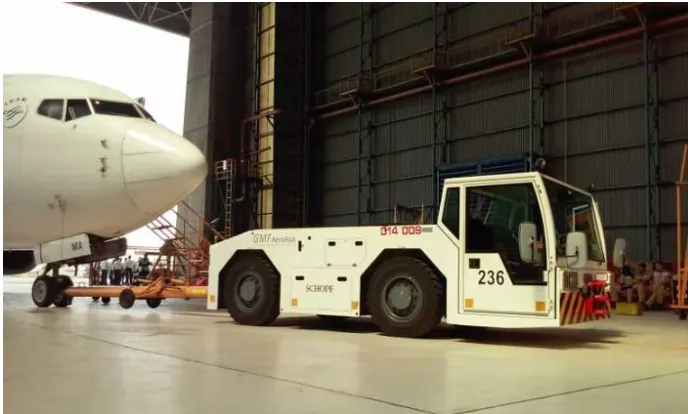
A Conventional Towing Tractor towing an aircraft into an aircraft maintenance hangar – a special facility at every airport where aircraft maintenance is carried out
Why is it called a tractor?
The story goes back to early days of aviation when airplanes used to land on open fields instead of concrete runways we have today. After landing, the nearest tractor available on the field was hooked to the aircraft to move it around. Although, engineers later developed a specialized vehicle for this job, but the name stuck and is still used today.
Why can’t aircraft move by itself?
It is obvious that an aircraft has its own engines so why can’t aircraft reverse itself from the aircraft bay? Why can’t aircraft move from one point to another at an airport on its own? After all, no pushback tractor is needed to maneuver an aircraft from the runway to airport gate after its landing. All these questions are valid and require scientific answers.
Starting with the pushback operation, let’s discuss why can’t an aircraft reverse itself from the bay. Majority airliners do have a reverse thrust mechanism that can theoretically allow it to reverse from the bay. This reverse thrust mechanism is used by pilots to slow the aircraft down after it has landed.
The reason why reverse thrust cannot be used is that it reverses the direction of jet thrust that can prove itself to be very dangerous on the bay. An aircraft bay is designed in a way that airport building and facilities are located in front of the aircraft.
Aircraft engines produce thrust by expelling high temperature and high velocity air behind the aircraft (and thus force the aircraft to move forward by Newton’s law of action and reaction). Reverse thrust mechanism will reverse the thrust and direct it towards the airport building and facilities such as the Passenger Boarding Bridge (Jet Bridge).
Due to this reason, an aircraft cannot reverse itself and thus requires an aircraft pushback tractor to push it back from the bay.
It is clear why an aircraft cannot reverse itself from the bay, however, the question that why can’t aircraft move from one point to another on an airport still remains. The answer lies in economics of jet engines vs. pushback tractor for on-ground movement.
An aircraft jet engine is not designed for moving an aircraft on ground at 10-30 km/hr (typical taxiing speed). It is designed for moving an aircraft at 700 km/hr cruising speed. Its fuel efficiency does not follow a linear pattern where lowering the speed would lower the fuel consumption by the same factor. Jet engines are as much fuel inefficient at low speeds as they are fuel efficient at their optimal speeds.
On the other hand, an aircraft pushback tractor has a diesel engine, gearbox and chassis especially designed for high torque and low speed operation. Its fuel consumption is far lower than a jet engine in the speed range typical for ground handling.
Due to above reason, airlines and ground handling agencies use pushback tractors for on ground maneuvering of the aircraft.
How a Conventional Pushback Tractor Works?
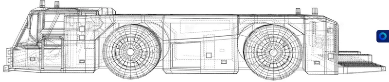
Now that we have developed a basic understanding of the purpose of a pushback tractor and its different uses, let us discuss the design of a conventional pushback tractor and how it works from a technical point of view.
A conventional pushback tractor is a diesel engine powered vehicle with a chassis design that keeps its body very low to the ground. The reason for low profile is to avoid collision with aircraft nose and keep a low centre of gravity that helps with stability.
A pushback tractor pushes the aircraft back by hooking itself to the aircraft with its towing hook – a special hook located on the nose landing gear (commonly referred to as the NLG).
Pushback tractor chassis needs to be as low to the ground as possible to ensure that the line of action of force at the time of pushback operation remains as much straight as possible to avoid bending of the towing bar – we’ll discuss shortly what tow bar is.
If the line of action is not straight, pushback tractor will tend to bend the towing hook more than trying to push the aircraft.
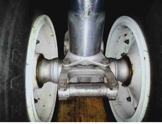
Towing hook is located on Nose Landing Gear (NLG) of an aircraft between the aircraft wheels
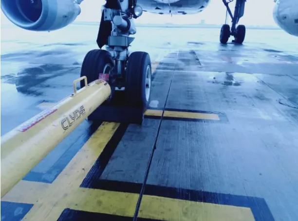
Towing bar hooks up to the towing hook on Nose Landing Gear (NLG) during pushback or towing operation
- Q-5=======>
-
In the physics realm Power">PowerPower = Mass x Acceleration x distance/time
To many it means "how much throttle" , which is how much fuel/time.
"Throttle" x prop efficiency = Thrust">ThrustThrust
This gives you a unit of Force that can be directly compared to glide data as follows:
Potential energy Mass x Gravity x altitude loss = Thrust">ThrustThrust x horizontal distance flown
This rearranged to Thrust">ThrustThrust = Mass x Gravity x altitude loss/horizontal distance flown
Thrust">ThrustThrust = force required for straight and level flight, expressed in "pounds or Newtons"
So if your plane weighs 10 lb and glides 5:1, you need 2 lb of thrust for straight and level flight.
One would at least double, or even triple this for "takeoff power", depending on your performance preferences. Sufficient "takeoff power" will give a safe climb rate to avoid difficulties with downdrafts.
For example: my plane glides 5:1 at 60 mph or around 5000 feet/minute and loses 1000 feet/minute. At 10 lbs it was calculated to need 2 lbs of thrust for straight and level flight.
How much more thrust do we need to climb 500 feet per/minute. Again, the glide data provides a very good estimate, 2 lbs x 500 fpm/1000 fpm = 1 lb additional or 3 lbs total at 60 mph. Higher speeds with more drag, or lower speeds "behind the power curve" will require more than 3 lbs of thrust.
- Source:https://aviation.stackexchange.com/questions/77714/what-is-takeoff-power/77716#77716?newreg=bd8186a0d5c34e8baed517c37ddd9998
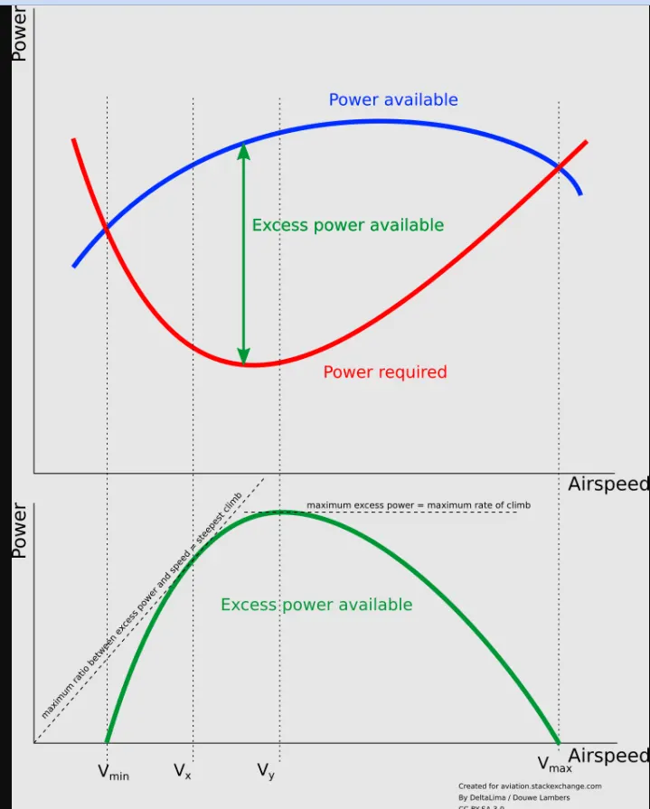
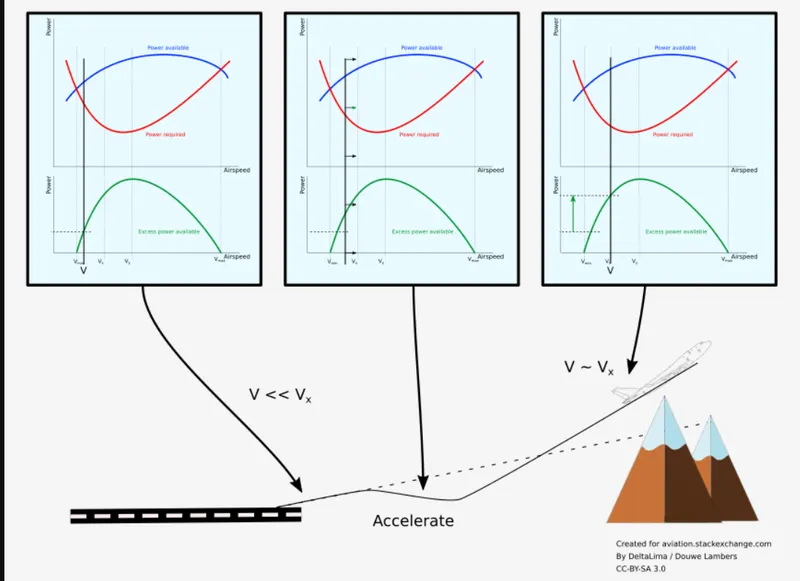
When an aircraft can barely climb after take-off, it may be flying on what is called 'the backside' of the power curve.
Flying at very low speed:
- costs a lot of power because of high induced drag
- means that the engines are inefficient because they are optimised for higher speeds.
As a result, the excess power available, that is the difference between the required power and the maximum available power, is very low when the aircraft flies close to the minimum flight speed. And the excess power is what is needed to climb the aircraft.
When the aircraft is flying below the speed at which the best angle of climb is achieved (Vx), it will be able to improve its climb angle by accelerating. To do so, the aircraft needs to use available power to accelerate, instead of using the power to climb.
Stopping the climb or even descending a bit will convert the available excess power and optionally height (potential energy) into speed. While this initially does not give extra clearance above the obstacle, the available excess power increases drastically. This in turn gives the ability to climb at a much steeper angle, allowing the aircraft to clear the obstacle.
determination of rolling resistance,take off power,tyre design,tyre pressure,brake forces when landing
- Measurement of forces and moments that act on a road wheel is a well known practice in automotive research and development. It is usually done either on laboratory test stands or on a test vehicle. Either way, a device that provides wheel forces and moments is a wheel dynamometer. A wheel dynamometer is a measuring device that enables to measure forces and moments acting on a wheel in real time on a moving vehicle. The majority of wheel dynamometer solutions comes from the automotive industry or research, and a typical solution has a form of a 6-element sensor that measures three orthogonal forces, FX, FY, and FZ, together with corresponding moments, MX, MY, and MZ.
- The measurement principle is based either on the strain gage or piezoelectric sensor technology. Some selected works that describe the use of such dynamometer systems for measurement of wheel forces and moments in various applications are included in the reference list.
- The horizontal force, FX, measured by a wheel dynamometer can be correlated with bending or shearing the grass plants, as well as soil deformation. The braking friction force can be correlated with sliding over the grass. The vertical force, Fz, depends the grass compression and can be used for coefficient calculations (braking friction, μ, and rolling resistance, kRR, coefficients, as well as aligning moment, MZ).
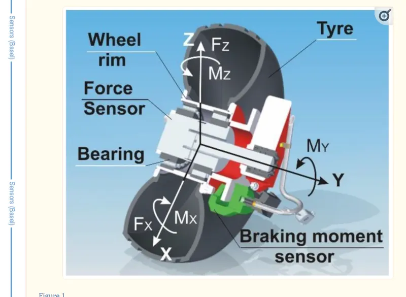
- fig-forces on a landing gear wheel of a plane
- The in-wheel transducer measures two forces, FZ and FX, and two moments, MZ and MX.\
- shows time courses of the vertical FZ and horizontal FX forces that act on the landing gear wheel. The FZ shows almost constant values with low fluctuations, probably caused by vertical vibrations of the entire aircraft rolling over the grassy surface, and those values are close to the aircraft weight component on the wheel. The horizontal force FX exhibits negative values since the sensor has a defined orientation and a force of the direction backwards is indicated as negative. Moreover, the course of the horizontal force FX reveals effect of wheel function modes: Free rolling (the first second of the course), acceleration increasing of the force’s values (between 1 and approximately 4 s of the course), braking to a full stop (5–9 s), and, again, acceleration (from approximately 9 s of the course). The peak maximum value of the horizontal force FX reaches 2.7 kN, but the average value is much lower.
-
Rolling Resistance Coefficient
Rolling resistance is a property of the tire–surface system and depends on many factors. In automotive technology, rolling resistance is determined for a tire rolling on a drum test stand and its coefficient takes essentially constant values, on the order of 0.010–0.012. In the case of a tire interacting with a deformable surface, such as grassy surface, rolling resistance is difficult to determine, mainly due to the changing conditions of the surface, which was mentioned in the introduction. In addition, the values of the rolling resistance coefficient of the tire–grass surface system can vary by as much as an order of magnitude, taking into account, for example, changes in soil moisture. The presence of vegetation (grass, roots), as well as the size and mass of green parts of vegetation, are also significant.
The rolling resistance coefficient, kRR, is defined as the ratio of horizontal force during free turning to vertical force [25]:
kRR = FX/FZ3.3. Braking Friction Coefficient
The braking friction coefficient μ is another important factor. It determines the course of the braking process and the landing distance of the aircraft. In the case of the tire–paved system (asphalt, concrete), the friction coefficient usually reaches values between 0.6–0.9. For unpaved surfaces such as grass turf, the friction coefficient is usually lower and may be 0.1–0.5. Factors affecting the μ value are grass length and humidity: The longer the grass and the more water it contains, the lower the friction coefficient. By definition, the friction coefficient is determined on the basis of the following relationship:
μ = MY/FZ × rdwhere rd is the dynamic radius of the tire.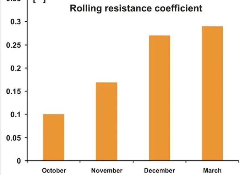 fig-Variation of rolling resistance wih change in seasons
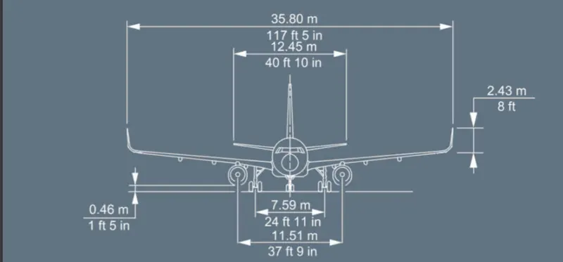
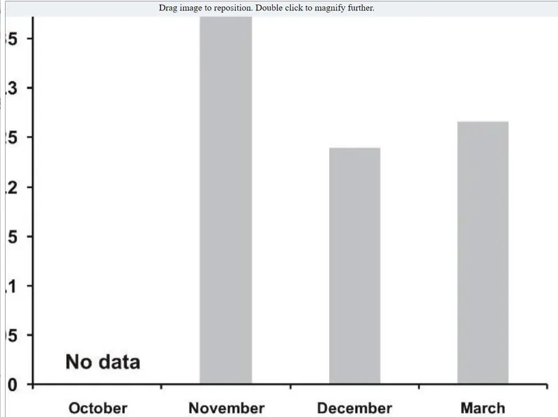 fig-variation of braking forces with change in temperature and pressure conditionsThe rolling resistance coefficient increases, and this is a significant increase. The explanation for that is quite obvious: In autumn, late autumn, winter, and early spring, there is a gradual increase in humidity of both air and soil, which causes increasing deformation of the surface and, as a result, an increase in rolling resistance--------------------------------------------------------------------------------------------------------------------------------------Q:6-A Let the mass of the truck be=7800kgspeed of the truck is assumed to be 30 kmphweight of the aircraft is 97400gwingspan = 35.8Height = 11.76massume:Air density (`rho`) = 1.225 Kg/m^3Drag Coefficient(Cd)=0.31Rolling resistance coefficient(`mu rr`) = 0.013Frontal area(A)=0.5m^2Gravitational constant(g) =9.81 m/s^2Calculation of rolling resistance:Frr = (`mu rr`)*m*g= 0.013*(7800+97400)*9.81= 13416.156NAir Drag CalculationFad= 1/2 `rho`*Cd*A*V^2=1/2 (0.013)*1*0.31*(30)^2= 450*0.37915= 170.8875N
 Assume: Gear ratio=8Transmission efficiency =85%;Motor efficiency = 90%;Torque required at the wheel = Total tractive force * radius of the wheel=21889.69*0.532=11645.32Nm.Motor Torque = (Wheel Torque)/(gear ratio* transmission efficiency)=(11645.32)/(8*0.85)=1712.55NmEfficiency = output/inputinput=output/efficiencyconsidering transmission efficiency and motor efficiencyTotal power required = (182.41kW/(0.9*0.85))=238.44kW
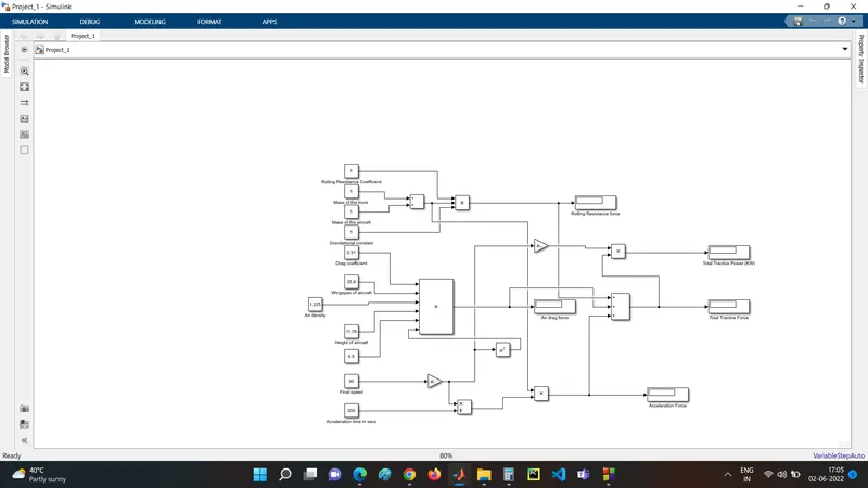 simulink model for calculation of force and total power required for towing operationThe constant blocks are used as an input and 2 gain blocks are used to multiply by a factor. Output is noted through display blocks. The output displays are air drag , rolling resistance,total tractive force, total tractive power,acceleration force.
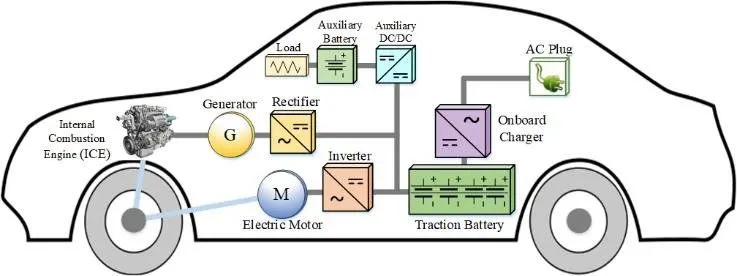 Powertrain of a vehicle refers to the components arrangement so as to meet the required energy. The above powertrain is of a plugin hybrid electric vehicle.The simulink model for the same is as follows and consists of DC7 block or four quadrant chopper. As the name suggests the power converter is capable to run the motor in all the four quadrants based on one of the four given conditions.1-Forward motoring (Torque is positive speed is positive,forward direction on uphill);2-Forward braking (Torque is negative and speed is positive,forward direction on downhill);3-Reverse motoring (Torque and speed both negative as in reverse direction on downhill );4-Reverse braking (Torque positive but speed negative,as in reverse direction on a uphill);The chopper is selected for two reasons:1 -To provide input voltage to the motor& 2 - To store back the voltage back in the battery when braking(regenerative braking)The construction of DC7 chopper is of IGBT which are hih voltage gain and high switching frequency devices as compared to traditional bjt's.
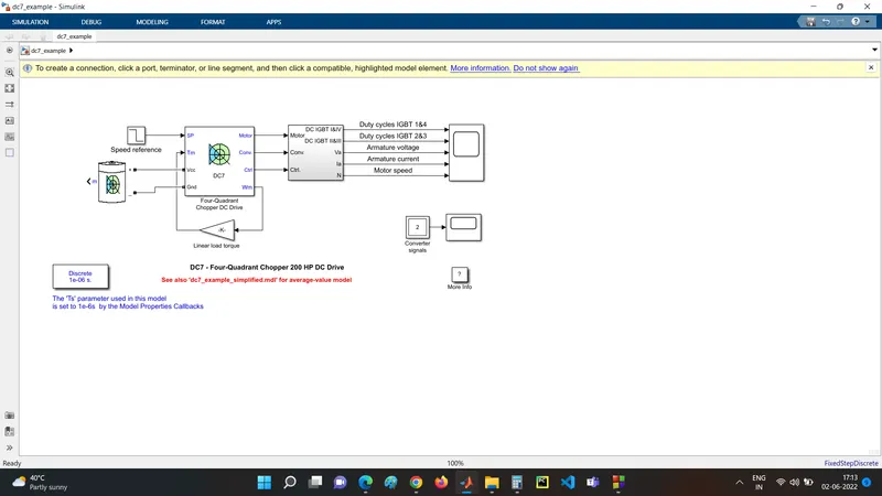 fig powertrain for EVAssuming time for towing operation as 30 minutes,Energy required 238.44kW*0.5If we consider the battery capacity as 280kW,Duty cycle for converter switches = 238.44/280=0.85=85%;Tyre specification of TMX-450Radius of wheel = 532 mmTotal tractive force = 21889.69NTotal power in kW = 182.41kW