Project-1: Powertrain for aircraft in runways
Project1
Objective:
- To Design an electric powertrain with type of motor, it’s power rating, and energy requirement to fulfill aircraft towing application in Simulink
What Is The Aircraft?
Any vehicle that is manufactured and made to fly in the air is called an aircraft. While the airplane is the most known, familiar, and popular kind of aircraft we know, other vessels that fly through the air also come in this category. All of them have propellers and wings or machinery to run through the air; however, they may vary according to sizes, types, usage, and more.
Classifications Of Aircraft:
-
Aerostats (Lighter Than Air): Aerostats or lighter than air aircrafts are very more lightweight in weight. These types of light aircraft generally use buoyancy like ships, which help them float in the air. Low-density gas such as hydrogen, helium, or hot air balloons is used to fill in the aircraft. This low-density gas is lighter than air, and hence the name. The most common types of aerostats known to us are hot air balloons and sky lanterns.
-
Aerodynes (Heavier Than Air): Alternatively, the other aircraft, heavier than air or aerodynes, as we understand, is much higher in weight and size. They push the gas or air downwards; which reaction helps to make aircraft upwards. Since these are dynamic through movements in the air, they are called aerodynes. This dynamic lift through the air can be caused mostly through mechanisms, as you must have already known.
- One is the fixed-wing classification, just like planes. In this category of fixed-wing aircraft, the entire mechanism is relied upon forward speed to create airflow all over wings.
- Another mechanism is rotorcraft, which uses spinning rotors that are like wings. The helicopter is the most commonly known aircraft under this classification.
Types Of Aircrafts In The World:
There are 18 types of aircrafts are available in the world some of them are
- Helicopters
- Muliti- Engine piston(Airplanes)
- Cargo planes
- Biplanes
- Ballons
- Glider,etc..
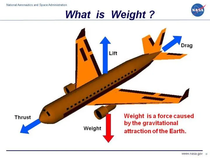
What is Weight?
Weight is the force generated by the gravitational attraction of the earth on the object.
Airplane weights:
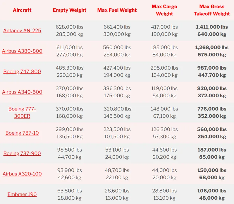
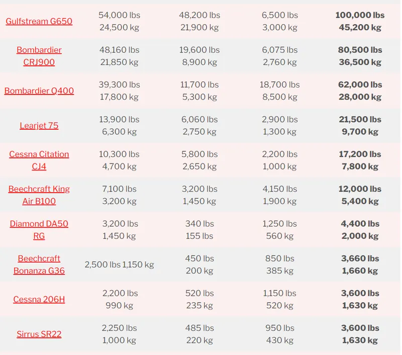
Airplane weights are not constant they will change while flying because of fuel,Airplane weights are measured as
- Empty weight - it consist of entire airplane wight excluded passenger/cargo/baggage weight /fuel weight(but it exclude coolents for engine).
- Max Fuel Weight - It consist of entirefuel weight like Trip fuel and reserve Fuel.
- Cargo weight - It consist of Passengers weight/Passengers baggage/Caro weights.
- Max Gross TakeOff Weight - Entire weight of an airplane at the time of Takeoff.
Maximum design taxi weight (MDTW)[edit]
The maximum design taxi weight (also known as the maximum design ramp weight (MDRW)) is the maximum weight certificated for aircraft manoeuvring on the ground (taxiing or towing) as limited by aircraft strength and airworthiness requirements.
Maximum design takeoff weight (MDTOW)
Is the maximum certificated design weight when the brakes are released for takeoff and is the greatest weight for which compliance with the relevant structural and engineering requirements has been demonstrated by the manufacturer.
Maximum design landing weight (MDLW)
The maximum certificated design weight at which the aircraft meets the appropriate landing certification requirements. It generally depends on the landing gear strength or the landing impact loads on certain parts of the wing structure.
The MDLW must not exceed the MDTOW.
The maximum landing weight is typically designed for 10 feet per second (600 feet per minute) sink rate at touch down with no structural damage.
Maximum design zero-fuel weight (MDZFW)
The maximum certificated design weight of the aircraft less all usable fuel and other specified usable agents (engine injection fluid, and other consumable propulsion agents). It is the maximum weight permitted before usable fuel and other specified usable fluids are loaded in specified sections of the airplane. The MDZFW is limited by strength and airworthiness requirements. At this weight, the subsequent addition of fuel will not result in the aircraft design strength being exceeded. The weight difference between the MDTOW and the MDZFW may be utilised only for the addition of fuel.
Minimum flight weight (MFW)
Minimum certificated weight for flight as limited by aircraft strength and airworthiness requirements.
Air Speed vs Ground Speed:
Wind Speed
For a reference point picked on the ground, the air moves relative to the reference point at the wind speed. Notice that the wind speed is a vector quantity and has both a magnitude and a direction. Direction is important. A 20 mph wind from the west is different from a 20 mph wind from the east. The wind has componentsin all three primary directions (north-south, east-west, and up-down). In this figure, we are considering only velocities along the aircraft's flight path. A positive velocity is defined to be in the direction of the aircraft's motion. We are neglecting cross wind, which occur perpendicular to the flight path but parallel to the ground, and updrafts and downdrafts, which occur perpendicular to the ground.
Ground Speed
For a reference point picked on the ground, the aircraft moves relative to the reference point at the ground speed. Ground speed is also a vector quantity so a comparison of the ground speed to the wind speed must be done according to rules for vector comparisions.
Airspeed
The important quantity in the generation of lift is the relative velocity between the object and the air, which is called the airspeed. Airspeed cannot be directly measured from a ground position, but must be computed from the ground speed and the wind speed. Airspeed is the vector difference between the ground speed and the wind speed.
Airspeed = Ground Speed - Wind Speed
On a perfectly still day, the airspeed is equal to the ground speed. But if the wind is blowing in the same direction that the aircraft is moving, the airspeed will be less than the ground speed.
Examples
Suppose we had an airplane that could take off on a windless day at 100 mph (liftoff airspeed is 100 mph). We are at an airport with an east-west runway that is 1 mile long. The wind is blowing 20 mph towards the west and the airplane takes off going east. The wind is blowing towards the aircraft which we call a headwind. Since we have defined a positive velocity to be in the direction of the aircraft's motion, a headwind is a negative velocity. While the plane is sitting still on the runway, it has a ground speed of 0 and an airspeed of 20 mph:
Airspeed = Ground Speed (0) - Wind Speed (-20) = 20 mph
The airplane starts its take off roll and has a constant acceleration a. From Newton's second law of motion, the ground speed V at any time t is:
V = a * t
and the distance d down the runway at any time is:
d = 1/2 * a * t^2
For a fixed length runway, this specifies the time to be used in the velocity equation. Let's assume that at 5000 feet down the runway, the velocity is 80 mph. Then the airspeed is given by
Airspeed = Ground Speed (80) - Wind Speed (-20) = 100 mph
and the airplane begins to fly. Now another pilot, with exactly the same airplane decides to take off to the west. The wind is now in the same direction as the motion and this is called a tailwind. The sign on the wind speed is now positive, not negative as with the headwind. The acceleration along the ground is the same, so at 5000 feet down the runway, the ground speed is again 80 mph. The airspeed is then given by:
Airspeed = Ground Speed (80) - Wind Speed (20) = 60 mph
This airplane doesn't have enough airspeed to fly. It runs off the end of the runway
3. Why is it not recommended to use aircraft engine power to move it on the ground at Airport?
- Aircraft engine power mostly used in ground only for taxing purpose ie for parking the aircraft from ruway to parking area and from parking area to runway.In taxing purpose only certain percentage of engine power is used.
- It is not recomended to use engine power because the thrust force will cause damage to working persons under the aircraft and to surrounding buildings.
- Due to engine power some debris/waste near surrounding of aircraft will suckby engine whic will damage the engine blade therby it will affect the engine performance.
- It will increase the fuel cost.
4. How an aircraft is pushed to runway when its ready to take off?
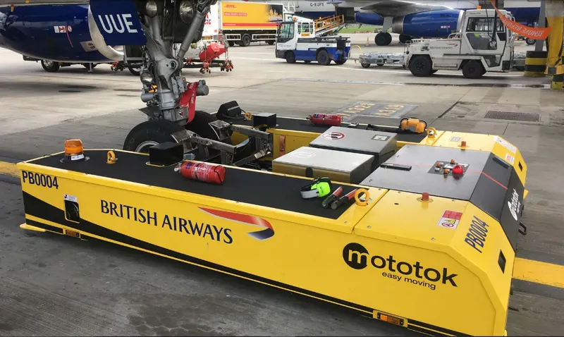
- Instead using engine power we can use a tug to push or pull an aircraft. The Tug may be an IC or an Electric engine.
- Using tug we can reverse the aircraft by attaching the tug to nose gear of an aircraft.
- We can increase the fuel efficiency
- Nowadays a wheeltug is the used to move the aircraft without atug vehicle.the nose gear of an aircraft consist of an electric motor which will be capable of moving aircraft forward and reverse.
5.Forces Acting on Airplane:
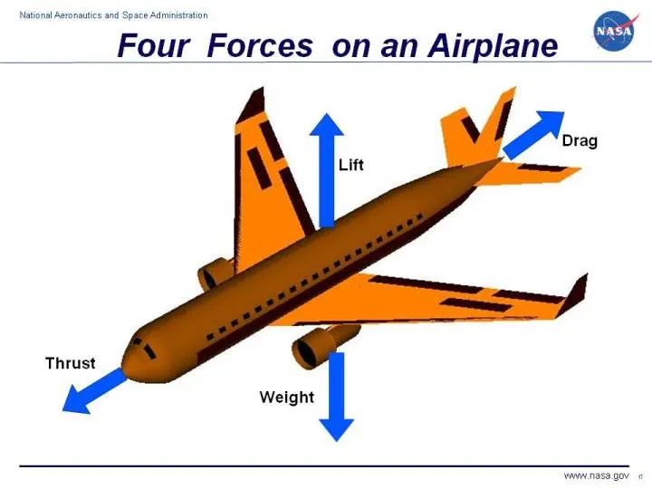
A force may be thought of as a push or pull in a specific direction. A force is a vector quantity so a force has both a magnitude and a direction. When describing force, we have to specify both the magnitude and the direction. This slide shows the forces that act on an airplane in flight.
Weight
Weight is a force that is always directed toward the center of the earth. The magnitude of the weight depends on the mass of all the airplane parts, plus the amount of fuel, plus any payload on board (people, baggage, freight, etc.). The weight is distributed throughout the airplane. But we can often think of it as collected and acting through a single point called the center of gravity. In flight, the airplane rotates about the center of gravity.
Flying encompasses two major problems; overcoming the weight of an object by some opposing force, and controlling the object in flight. Both of these problems are related to the object's weight and the location of the center of gravity. During a flight, an airplane's weight constantly changes as the aircraft consumes fuel. The distribution of the weight and the center of gravity also changes. So the pilot must constantly adjust the controls to keep the airplane balanced, or trimmed.
Lift
To overcome the weight force, airplanes generate an opposing force called lift. Lift is generated by the motion of the airplane through the air and is an aerodynamic force. "Aero" stands for the air, and "dynamic" denotes motion. Lift is directed perpendicular to the flight direction. The magnitude of the lift depends on several actors including the shape, size, and velocity of the aircraft. As with weight, each part of the aircraft contributes to the aircraft lift force. Most of the lift is generated by the wings. Aircraft lift acts through a single point called the center of pressure. The center of pressure is defined just like the center of gravity, but using the pressure distribution around the body instead of the weight distribution.
The distribution of lift around the aircraft is important for solving the control problem. Aerodynamic surfaces are used to control the aircraft in roll, pitch, and yaw.
Drag
As the airplane moves through the air, there is another aerodynamic force present. The air resists the motion of the aircraft and the resistance force is called drag. Drag is directed along and opposed to the flight direction. Like lift, there are many factors that affect the magnitude of the drag force including the shape of the aircraft, the stickness of the air, and the velocity of the aircraft. Like lift, we collect all of the individual components' drags and combine them into a single aircraft drag magnitude. And like lift, drag acts through the aircraft center of pressure.
Thrust
To overcome drag, airplanes use a propulsion system to generate a force called thrust. The direction of the thrust force depends on how the engines are attached to the aircraft. In the figure shown above, two turbine are located under the wings, parallel to the body, with thrust acting along the body centerline. On some aircraft, such as the Harrier, the thrust direction can be varied to help the airplane take off in a very short distance. The magnitude of the thrust depends on many factors associated with the propulsion system including the type of engine, the number of engines, and the throttle setting.
For jet engines, it is often confusing to remember that aircraft thrust is a reaction to the hot gas rushing out of the nozzle. The hot gas goes out the back, but the thrust pushes towards the front. Action <--> reaction is explained by Newton's Third Law of Motion.
The motion of the airplane through the air depends on the relative strength and direction of the forces shown above. If the forces are balanced, the aircraft cruises at constant velocity. If the forces are unbalanced, the aircraft accelerates in the direction of the largest force.
Tires
The tire (tyre in British English) is the only part of the aircraft in contact with the ground, and a well-maintained set of tires is crucial to the safe operation of any aircraft. Tires cushion the impact on touch-down and transfer the energy of landing into the wheels.
Aircraft tires differ substantially in their operating profile to automotive tires. Car tires are load bearing for a considerably longer time than an aircraft during a typical mission profile, albeit at relatively low speeds with slow accelerations. Aircraft tires on the other hand spend comparatively less time operating but must absorb very large impact loads and handle high speeds with large accelerations when in contact with the runway. Aircraft tires are designed to flex far more than automotive tires which assists in damping the large impact loads.
Tire Classification
Tires are typically classified according to their dimensions, strength (ply-rating) and configuration (tubed or tubeless). To ensure safe operation, the correct tire should always be fitted to a particular aircraft in accordance with the operating manual.
DIMENSIONS AND SIZING
Dimensional classification is usually made according to outer tire diameter, sectional width, and the diameter of the rim. A common classification system in use today is that of the United States Tire and Rim Association, where aircraft tires are classified as one of nine types.
Today, three tire classifications cover almost all aircraft classes in use, from light aircraft up to modern jet airliners. These three classifications use a slightly different way to report the tire dimensions; this is described below.
Type III
Type III tires are common low-pressure general aviation tires predominantly used on light aircraft with reasonably low landing speeds. These tires are easily identified as they have a small rim diameter in comparison to their width. Type III tires are designated by a two-number system: the first number describes the nominal tire width and the second the diameter of the rim that the tire can be fitted to. The two numbers are separated by a dash.
Type VII
Type VII tires are high-pressure, high performance tires fitted to jet aircraft. These tires are sized according to a two-number system that differs from the Type III classification described above. Here the first number designates the nominal overall diameter of the tire while the second number, which is separated from the first by a multiplication sign, gives the nominal section width.
Type VIII
Type VIII tires are designated by three numbers and incorporate the conventions of both the Part III and Part VII tires. The first number specifies the outside diameter, the second is the nominal tire width, and the third is the rim diameter. These tires are designed to operate at high-pressures and high speeds and are the most advanced tires in use on large jet aircraft today.
PLY RATING
Ply-rating provides an indication of the relative strength of the tire. The strength of early tires was directly proportional to the number of reinforcing plies present in the design which is how the ply rating system originated. Nowadays, the use of modern materials and complex manufacturing techniques have rendered the actual ply count somewhat irrelevant when discussing to the strength of a tire. However, a ply-rating system (now decoupled from actual ply count) is still used to describe the relative strength of one tire against another and remains an important indicator of tire strength.
TUBED OR TUBELESS
Aircraft tires are either designed to use an inflatable tube to provide the required pressure or seal directly onto the wheel without a tube. Tubeless tires are built with an inner lining to prevent air leaks and are stamped with the word “tubeless” on the tire sidewall. Tubeless tires are lighter than tubed tires and are less susceptible to tire creep, which occurs when the tire shifts relative to the wheel during a hard impact.
Construction
A tire follows a layered construction approach where each layer (region) of the tire serves a different purpose. Broadly speaking, a tire can be divided into four specific regions: the bead, ply, tread and sidewall.
Refer to the image below which shows the make-up of a typical aviation tire.
BEAD
The bead consists of bundles of high strength steel wire encased in rubber. This provides the tire with lateral strength, anchoring the structural plies and transferring the impact loads generated in the tire onto the wheel rim. Tires that are designed to operate at higher speeds and at higher loads may have multiple bundles of beading to effectively transfer the loads and resist the large tire deformations that result.
PLY REGION
A tire is built from multiple plies which are laid on top of each-other to give the tire its structure and form. Plies are usually manufactured from nylon fabric sandwiched between layers of rubber. These structural members are sometimes called carcass plies as they form the skeleton of the tire. The concept of ply rating refers to the relative strength of the tire’s ply layup. The ends of each ply are anchored to the beading on each side of the tire to transfer load out the tire and into the wheel.
Plies are characterised according to their orientation relative to the direction of motion of the tire. Traditionally, plies were orientated predominantly in the direction of motion of the tire (with a bias of between 30° and 60°). This is called a bias ply layup as the plies are orientated with a bias to the direction of rotation. Bias plies result in a tire that is flexible and able to absorb the loads typically seen during landing and take-off.
A radial ply layup is one where the plies are laid perpendicular to the direction of motion of the tire. This results in a stronger tire, but one that is not able to deflect and flex as much as in a bias ply layup.
TREAD
The tread refers to the wearable part of the tire that is designed to come into contract with the ground. The tread is located on the tire crown and must resist frictional wear, abrasion, cracking and cuts that occur as a result of the landing surface and condition of the runway.
The tread pattern seen on the tire differs according to the operational requirements of the tire. Most tires are grooved in the circumferential direction which provides good operating characteristics for aircraft generally flown into and out of prepared runways. The grooves that characterize a rib tread tire assist in cooling the tire and provide a means for water to channel away from the tire in wet conditions.
Aircraft operating from unprepared or unpaved surfaces may be fitted with a cross-tread pattern. This diamond pattern is cut deep into the tire and provides more traction that the rib tread design in soft ground. On a hard surface (asphalt runway) the tire has a smaller total contact area and so will provide less traction that a tire with a rib tread.
Some older aircraft may have a smooth tread with no ribs or cut-outs. This provides the greatest traction, largest contact area, and subsequently the greatest frictional force which assists in stopping the aircraft.
SIDEWALL
The sidewall of a tire is designed to protect the plies (carcass) that gives the tire its strength. Information about the tire: its dimensions, speed rating, ply rating, direction of rotation, manufacturer etc is printed on to the sidewall for easy reference. The inner sidewall is covered by an inner liner which is a thin rubber liner designed to prevent damage to the carcass plies. Small vent holes in the sidewall are built-in to allow trapped air in the plies to escape. This helps prevent delaminations between plies from forming as a result of the trapped air expanding due to altitude and temperature changes.
Tire Wear and Creep
TIRE WEAR
Tires that are operated at the incorrect inflation pressure result in an uneven tread wear that could be detrimental to the safety of the tire. The nature and severity of the wear can alert the pilot as to whether the tire is over or under-inflated. Considerable traction is lost when a tire has worn beyond its limits and should always be replaced or retreaded rather than left to operate in a poor condition.
A tire that is over-inflated will tend to wear towards the center of the tread. This is because at higher inflations, a smaller area of the tire is in contact with the ground and so wear is highest in this region.
Conversely, under-inflated tires will wear towards the tire shoulders as the tire sags onto the ground with a corresponding increase in friction. This can lead to the tire overheating, damage to the carcass, and the tire creeping or pinching at the sidewall.
CREEP MARKINGS
Hard landings and heavy braking, particularly if the tire is under-inflated, can lead to movement of the tire relative to the wheel in the direction of rotation. Rotation of the tire around the rim is referred to as tire creep or slip and should be avoided. Creep in a tubed tire is particularly undesirable as this could cause the tube valve to rupture, resulting in a blow-out.
Tire creep is often monitored by painting a single white line over the tire and wheel once the tire is installed and inflated to the correct pressure. Any slip is easily identified as the line on the tire and wheel move out of alignment. Acceptable creep limits are established by the tire manufacturer and often creep markings are moulded into the sidewall between which the line across the wheel and tire is drawn. Once the alignment moves beyond the limits bounded by the markings, the creep is deemed too severe and must be addressed.
How do aircraft brakes work?
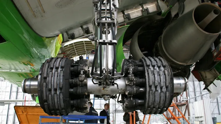 Landing gear and brakes on an Airbus A319-114 operated by Siberia Airlines. Source: Gleb Osokin / CC-BY SA 3.0
Aircraft brakes stop a moving aircraft by converting its kinetic energy to heat energy by means of friction between rotating and stationary discs located in brake assemblies in the wheels.

A brake assembly on a Boeing 737NG main landing gear, visible after removal of one the wheels. Source: SKYbrary (Click image to enlarge)
Brakes provide this critical stopping function during landings to enable airplanes to stop within the length of the runway. They also stop aircraft during rejected takeoff events, in which an attempted takeoff is canceled as the airplane is rolling down the runway before it lifts off from the ground due to engine failure, tire blowout, other system failure or direction from air traffic control.
Aircraft brakes also prevent motion of the aircraft when it is parked, limit its speed during taxiing and can even help steer the aircraft on the ground by applying different levels of braking force to the left- and right-side brakes.
Aircraft brakes work in conjunction with other brake mechanisms such as thrust reversers, air brakes and spoilers. Thrust reversers are surfaces that are deployed into the path of the jet blast from the engines to redirect propulsive thrust in a direction that opposes the motion of the aircraft. Air brakes and spoilers are flight control surfaces that create additional aerodynamic drag when deployed into the path of air flowing around the aircraft.
How aircraft brakes work
The most common type of brake used on aircraft is the disc brake. Disc brakes function by exploiting friction between rotating and stationary discs inside the brake.
Upon receiving a command signal to brake — from the pilot depressing a foot pedal or from the autobrake system — actuators in the brake move a piston to squeeze the discs together, generating a frictional force that slows the rotation of the wheel. The friction between the discs generates heat as the aircraft’s kinetic energy is converted to heat energy. In this function, the brakes act as a heat sink, absorbing tremendous amounts of heat as the aircraft sheds kinetic energy. During RTO stops, the temperature of carbon disc brakes can exceed 1,800° C.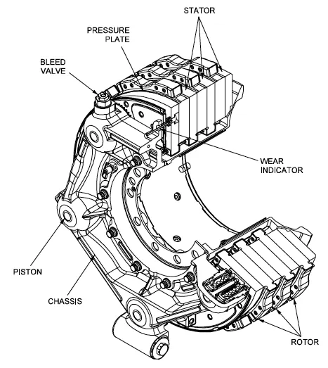 Gulfstream G450 main landing gear brake assembly. Source: G450 Maintenance Manual via Code 7700
The discs are mounted on a carrier assembly consisting of a torque tube, which resists and transmits brake torque to the landing gear structure. Sandwiched together between the carrier assembly housing and a backing plate, the discs are arranged in an alternating pattern of rotors and stators. Notch and groove geometry around the circumference of each rotor fits into corresponding geometry in the wheel, keying the rotors to the wheel so that they rotate with it. The stators are keyed to the torque tube and are thus held stationary since the torque tube is connected to the axle and landing gear structure.
Cylindrical spaces within the carrier assembly hold actuator pistons. Braking occurs as piston force squeezes the discs together.
During each application of the brakes, disc material is worn away by frictional forces. A wear indicator in the form of a pin that protrudes out of the carrier assembly indicates the thickness of the stack of discs. Over hundreds of brake applications, material wears away and discs become thinner, requiring replacement following periodic maintenance intervals.
Brake design
The primary design considerations for aircraft brakes include the number of discs, the diameter of the discs and the material of the discs.
A major design point around which aircraft brakes are designed is the worst-case scenario of rejected takeoff (RTO) at the maximum rolling speed V1, known as the decision speed. Above V1, a takeoff could not be safely aborted without serious risk of the airplane failing to stop before the end of the runway. In this situation, the brakes need to absorb more energy than any other scenario.
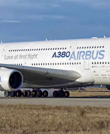
An A380’s brakes exhibit a red-hot glow during a rejected take off (RTO) test on the runway at ISTRES AFB in the south of France. Source: Airbus (Click image to enlarge)
To illustrate how much energy this is, consider an Airbus A380 — the world’s biggest passenger airplane — performing an RTO at V1. The maximum take-off weight of an A380 is 575,000 kg (1,267,658 lb) and its maximum V1 is around 170 knots (about 195 mph or 87 m/s). A rough estimate for the maximum energy that the A380’s 16 brakes need to dissipate during RTO can be obtained by calculating the kinetic energy of the aircraft (neglecting the effects of thrust reversers, air brakes, tailwinds, headwinds and runway slope).
Since kinetic energy (KE) is a function of mass (m) and velocity (v) according to the equation:
KE = ½mv2
The kinetic energy of the A380 during RTO is calculated as follows:
KE = 0.5 * 575,000 kg * (87.4556 m/s)2 = 2.2 x 10⁹ J = 2.2 GJ
2.2 GJ (gigajoules) is about the amount of energy an average cloud-to-ground lightning strike dissipates. It is also enough energy to power an 8 W LED light bulb (with light output equivalent to a 60 W light bulb) continuously for 8 years and 10 months.
To generate the necessary frictional forces and to handle this much energy within the length of a runway, large commercial transport aircraft typically require multiple discs per brake assembly and brakes on most, if not all, of their wheels.
For example, an A380 has 22 wheels distributed on five landing gear legs to support its massive weight: two nose wheels on a leg beneath the nose of the aircraft, eight wing wheels split between two legs that fold out from under the fuselage to support the left and right wings, and 12 body wheels split between two inboard landing gear legs under the fuselage. Sixteen of these wheels have brakes (four aft body wheels and the nose wheels are not braked).
Part-B
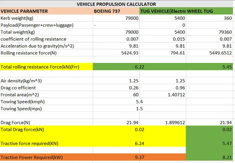
Calculation of power Recquired:
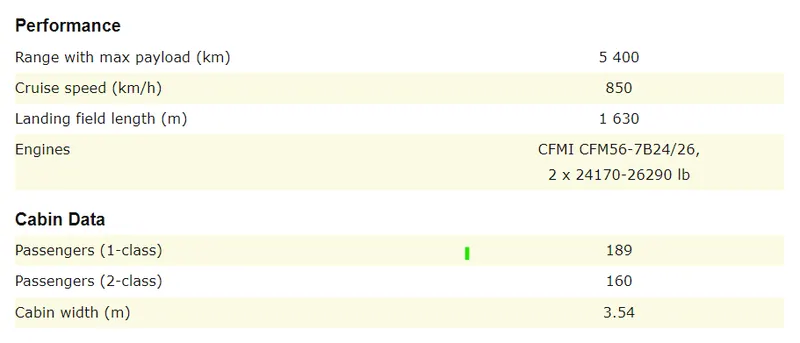
Airpalne details: BOEING 737
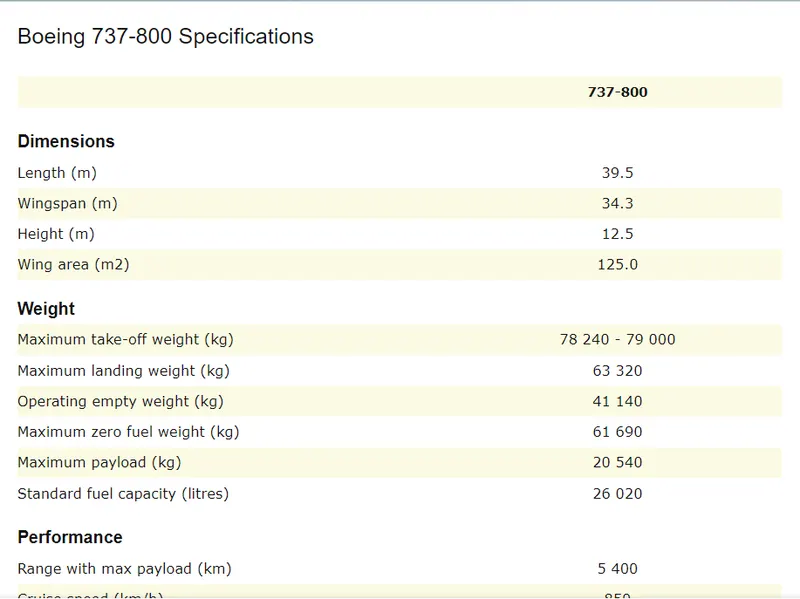
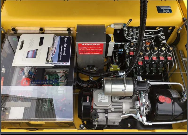
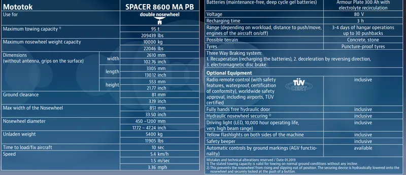
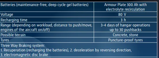
Tug vehicle specifications: MOTOTOK SPACER 8600.
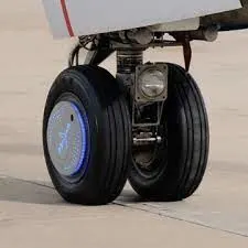
WHEEL TUG:
- Wheel tug is acompany that provide solution for taxing related problems for aircraft.
- The solution is a electric motor is attached to nose gear of a system,which will perform the taxing option without the tug.
- The motor is powered by internal auxillary supply generator from aircraft
- This has additional advantages of electric braking while landing.
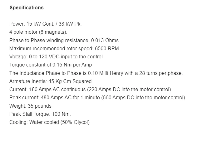
MOTOR SELECTION:
So from above calculation we recquired 5.24kN(Airplane alone) or 6.24kN (for both airplane and tug vehicle) of force to tow an airplane(Boeing 737).
The total power required to tow an aircraft is
`Power = F*v`
Tractive power = 6.24* 1.5(5.4kmph)= 9.37kW
Torque = Tractive force * Angular speed
= 9.36 * 28.65
Torque = 268.136 Nm
- We want to select a motor whose continious power rating must be greater than 9.5kW
- Here speed of towing is around 6kmph if we want more speed then power required also increases,so i considered a 15kW/20hp motor
Energy Calculation:
- Energy required = Power*time
= 15 * 0.33(20min of operation)
= 5.15kWh. of energy required for 20 min of operation.
Duty cycle calculation:
`w = (D*v)/(k*theta)*(R_a*T)/(k*theta)^2`
substituting the value above we will get the duty cycle we will get 75% duty cycle
Duty cycle:
let we assume we have around 90% efficiency for overall system
so Efficiency = output power/ inputpower
input power = input voltage*input current
input voltage = duty ratio * battery voltage
so duty ratio =
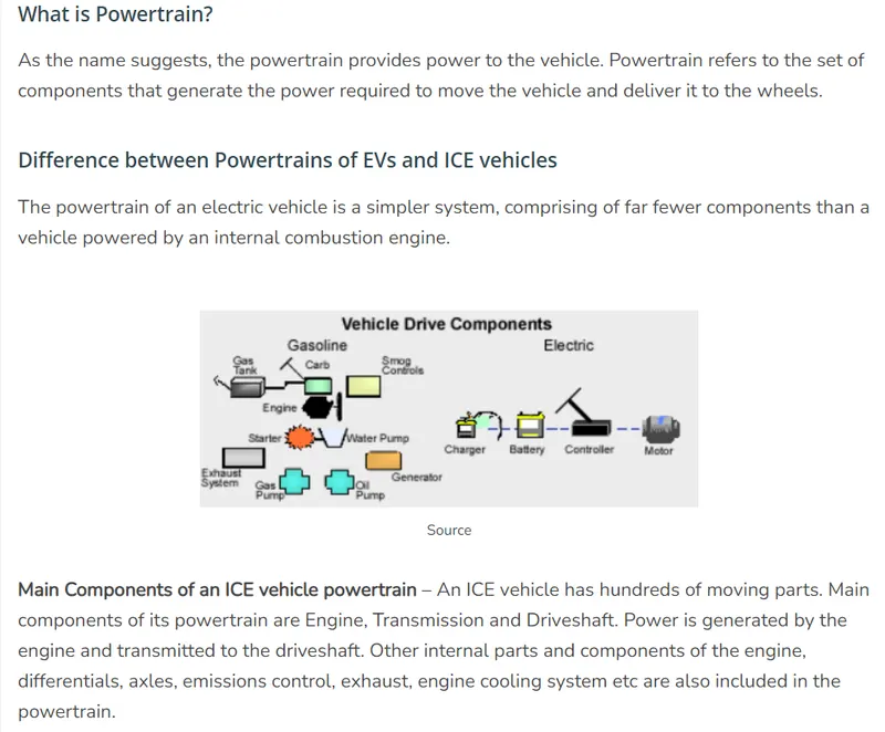
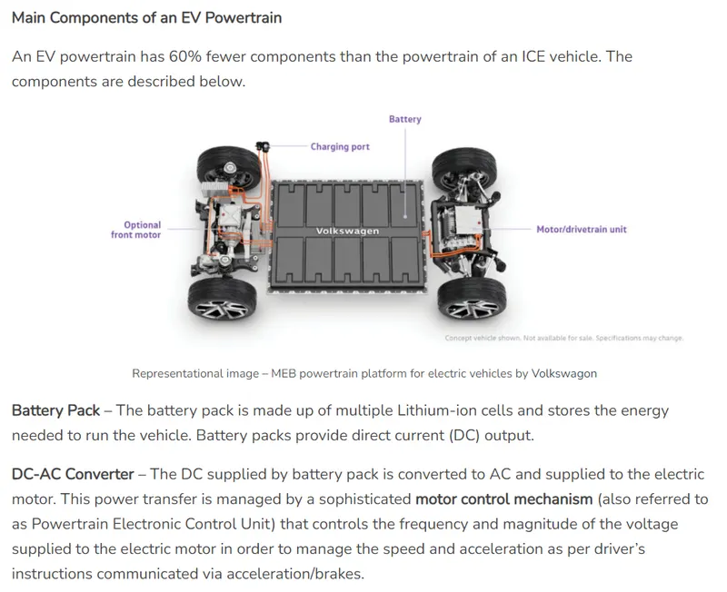
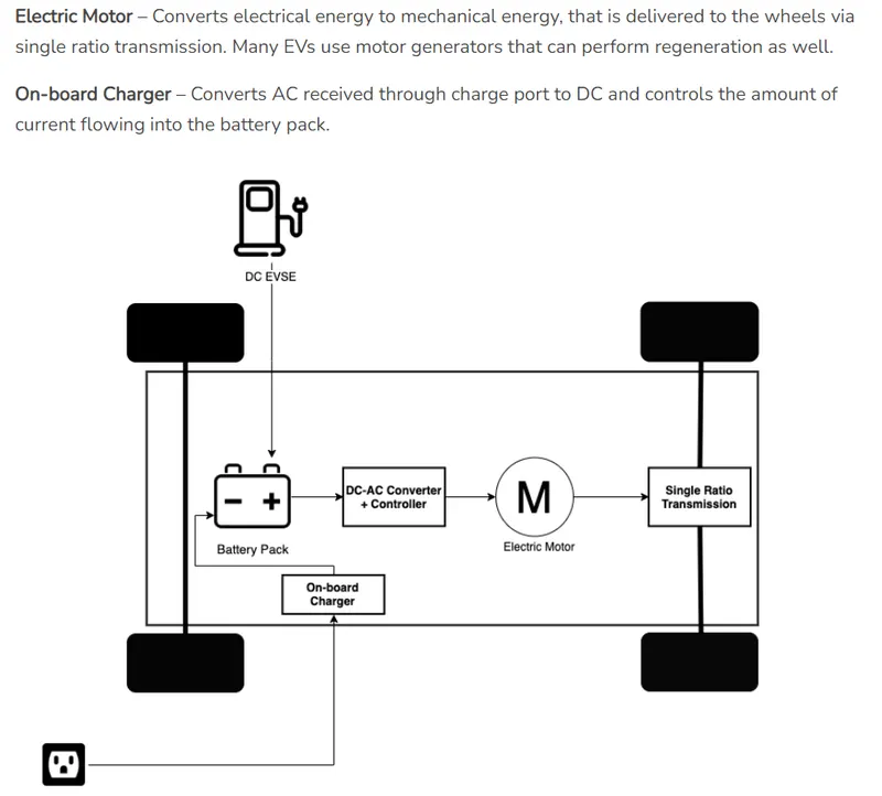
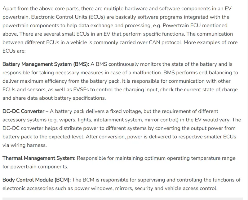
ELECTRIC POWERTRAIN MODEL:
References:
https://evreporter.com/ev-powertrain-components/
https://cdn2.hubspot.net/hubfs/1835281/downloads/factsheet-spacer-en.pdf
https://www.nasa.gov/audience/foreducators/k-4/features/F_Four_Forces_of_Flight.html
https://en.wikipedia.org/wiki/Pushback
https://www.mototok.com/blog/5-types-of-aircraft-tugs
https://www.airlines-inform.com/commercial-aircraft/boeing-737-800.html