Project-1: Powertrain for aircraft in runways
AIM: -
To design and analysis Powertrain for aircraft in runways using Simulink.
OBJECTIVE: -
- Calculate the force and power required to push / pull an aircraft by a towing vehicle and model in Simulink.
- Design an electric powertrain with type of motor, its power rating, and energy requirement to fulfil aircraft towing application in Simulink
- Estimate the duty cycle range to control the aircraft speed from zero to highest
- Draw a block diagram of powertrain in Simulink.
GOVERNING EQUATION: -
`Ft = Fr + Fhc + Fad`
`Frr =μ * m* g`
`Fad =1/2 *cd*ρ*A*V^2`
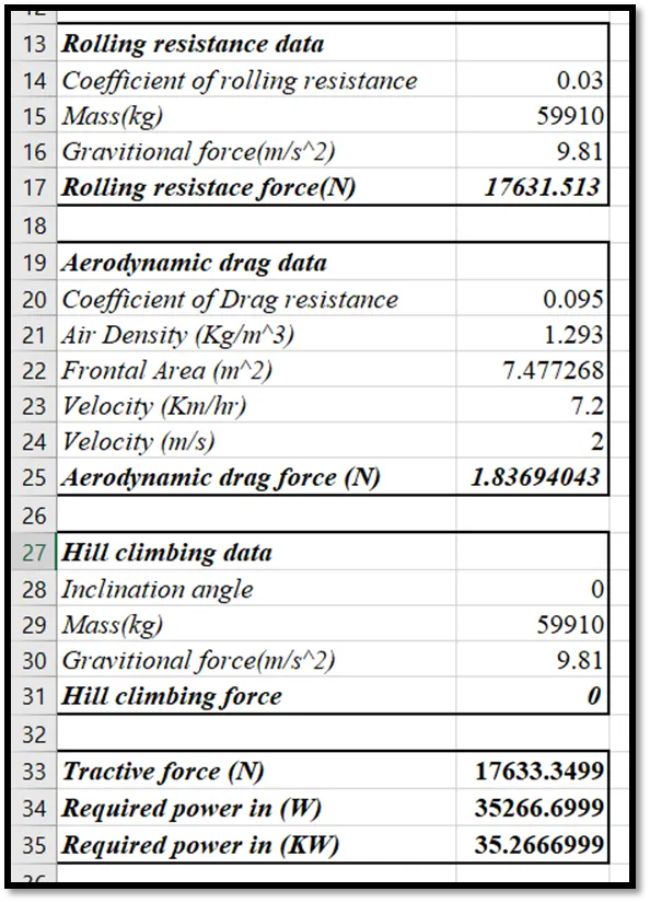
1.A. The force and power required to push / pull an aircraft with a towing vehicle.
Assumption:
- plane runway is flat there is no hill climb so Hill climbing force is zero.
- The towing Vehicle is running at a very low constant speed so the Air drag force is very minimum or zero.
Here we have to calculate the Tractive force to pull the aircraft.
So tractive force is nothing but the sum of rolling resistance force, hill climb force and aerodynamic drag force.
`Ft = Fr + Fhc + Fad`
Were,
Ft = tractive force
Fr = Rolling resistance force
Fhc = Hill climbing force
Fad = Air drag force
As we know there is no hill climb force and air drag force is very minimum so,
`Ft = Fr + Fad`
Rolling resistance force: -
`Frr =μ * m* g`
Were,
Frr = Rolling resistance force
=Rolling resistance coefficient
m = Mass of aircraft + towing vehicle
g = Gravitational force (9.81m/s^2)
Air drag force: -
`Fad =1/2 *cd*ρ*A*V^2`
Were,
Fad = air drag force
C = Drag coefficient
rho = Density of air
A = Frontal area
V = Velocity of towing vehicle
Hill climbing force: -
`Fhc = m*g*sinφ`
Were,
`φ`= Inclination angle
Consideration: -
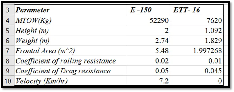
Aircraft E -195, https://en.wikipedia.org/wiki/Embraer_E-Jet_family

MTOW = 52290 kgs
Height = 2 m
width = 2.74 m
Frontal Area = 4.74 m^2
Tyre specifications: - 42/16 R 20
Towing Vehicle ETT- 16, https://eagletugs.com/aircraft-tugs/eagle-tt-electric-aircraft-tugs-ett-16
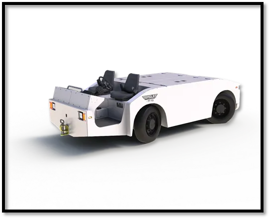
Weight with Battery = 7,620 kgs
Height = 1,092 mm
width = 1,829 mm
frontal Area =1.98 m^2
Tyre specification: - 215/75 R 17.5 LRF
1.B Model for the calculated force and power using Simulink.
2. Design an electric power train with type of motor, its power rating, and energy requirement.
Tyre specifications: -
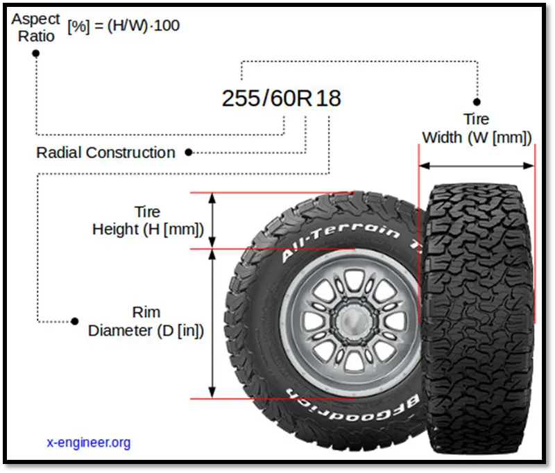
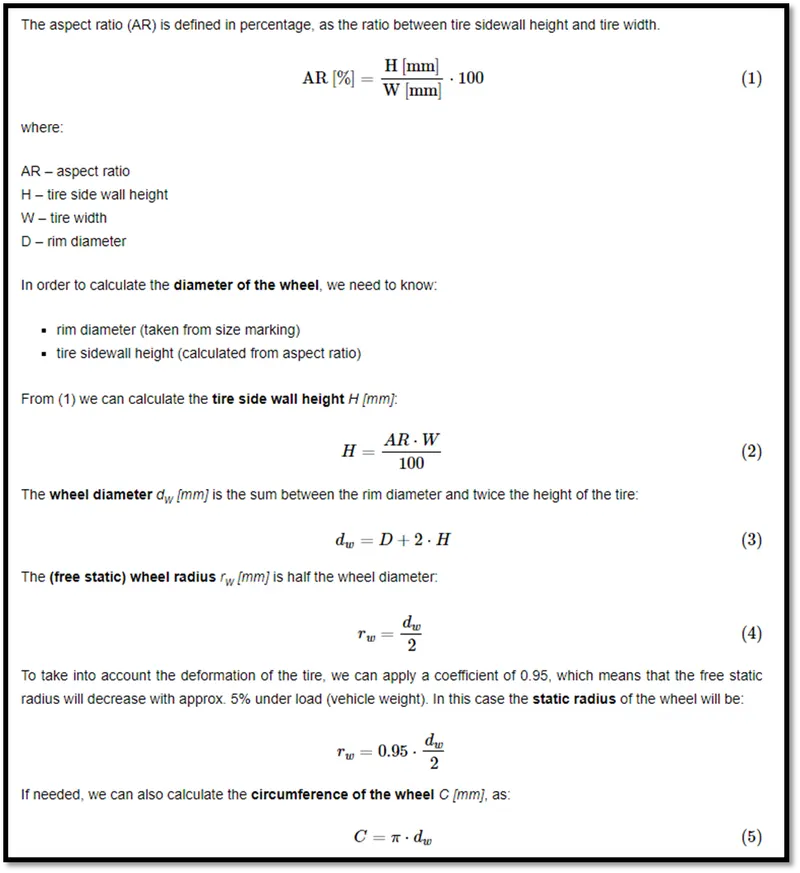
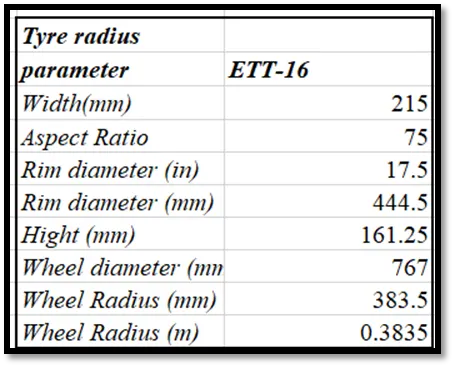
From the above figure we get Tyre radius for energy calculation,
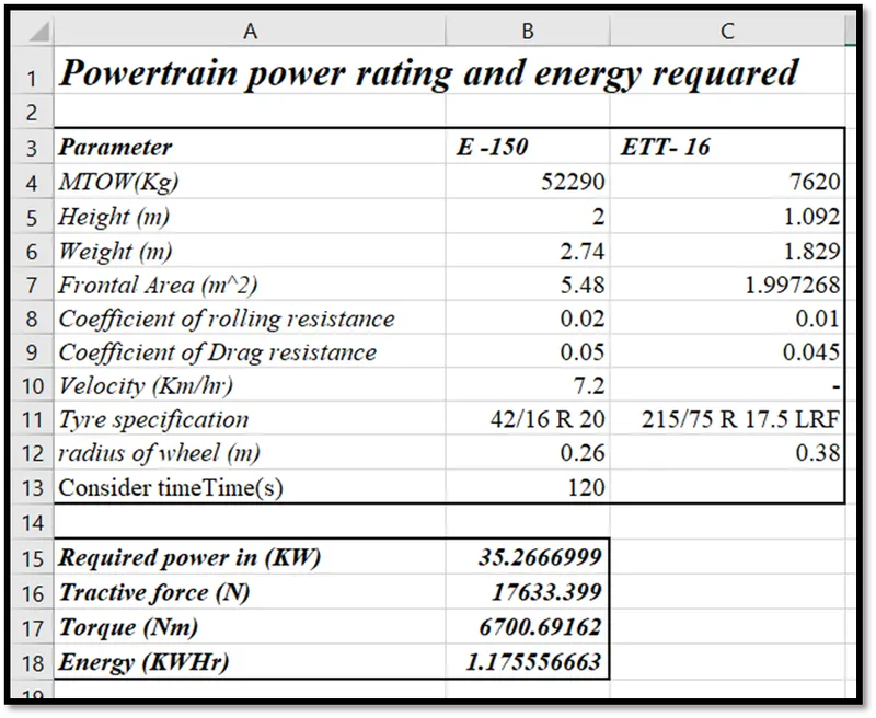
Motor: -
We require a motor which has a higher starting torque and high efficiency. We can use series dc motor for high starting torque but the dc series motor's Torque drops sharply when the speed increases and losses are high as compare to BLDC motor. Over the dc series BLDC motor have some advantages as follow,
- Better speed versus torque characteristics
- High dynamic response
- Less overall maintenance due to lack of brushes;
- Operates effectively at all speeds with rated load;
- High efficiency and high output power to size ratio;
- Long operating life due to a lack of electrical and friction losses
- Noiseless operation
- Higher speed ranges
For the above reason we are using BLDC motor.
Power Train = 80V A/C ELECTRIC
Traction Motor = Danaher Motion - 80V A/C BLDC
Output @ 1300 rpm = 55 HP / 41 kW (Peak)
Torque (Electric) = 210 ft lbs / 284 Nm
Duty cycle: -
Here we consider the transmission efficiency and motor efficiency is 100 %
Duty cycle = (Output power/ Input power) *100
Duty cycle = (35.27/ 41) *100
Duty cycle = 86.02%
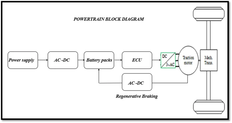
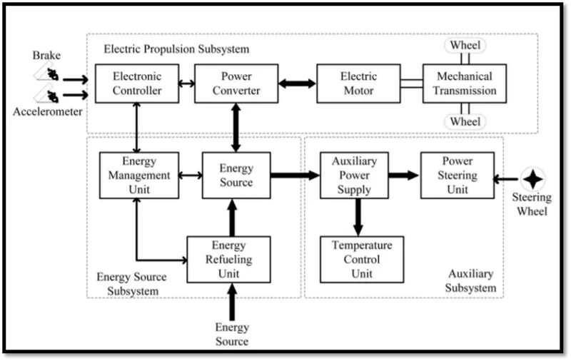
Simulink model: -
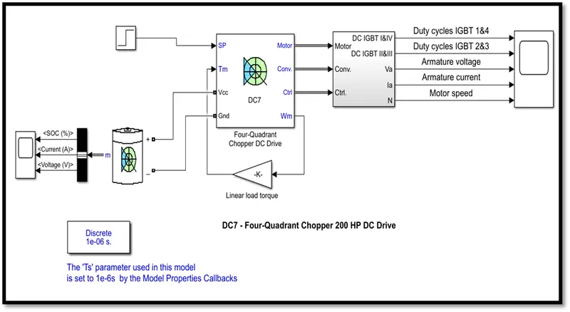
- Here we take dc 7 chopper as dc motor with controller for towing vehicle.
- The input for speed is given by step block.
- The battery block is added for dc voltage source to dc 7 chopper,
- The armature voltage is provided by an IGBT converter controlled by two PI regulators.
- The first regulator is a speed regulator, followed by a current regulator. The speed regulator outputs the armature current reference (in p.u.) used by the current controller in order to obtain the electromagnetic torque needed to reach the desired speed.
- The speed reference change rate follows acceleration and deceleration ramps in order to avoid sudden reference changes that could cause armature over-current and destabilize the system.
- The current regulator controls the armature current by computing the appropriate duty ratios of the 5 kHz pulses of the four IGBT devices (Pulse Width Modulation).
- For proper system behaviour, the instantaneous pulse values of IGBT devices 1 and 4 are opposite to those of IGBT devices 2 and 3. This generates the average armature voltage needed to obtain the desired armature current.
Results: -
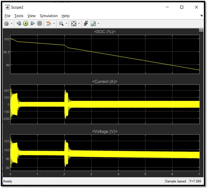
In above result we can see that the soc of battery decrease till 99.5 % in 7 seconds. At 2sec the current goes negative so the regenerative braking is taking place after 2.2 sec it will be stable.
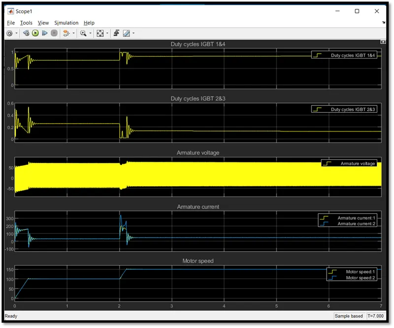
You can observe the motor armature voltage and current, the four IGBT pulses and the motor speed on the scope. The current and speed references are also shown.
The amateur current follows the current reference very well.
CONCLUSION: -
We can conclude here we have designed a powertrain for towing vehicle with the help of standard data sheet parameters to calculate the forces, power, energy, motor specification. Here we used dc7 chopper as DC motor and power electronics to conversion and control the motor. Battery parameters are decided on the basis of motor input parameters.
References: -
- https://www.rotablerepairs.com/embraer-erj190.html
- https://eagletugs.com/aircraft-tugs/eagle-tt-electric-aircraft-tugs-ett-16
- https://x-engineer.org/calculate-wheel-radius/
- https://en.wikipedia.org/wiki/Embraer_E-Jet_family
- https://in.mathworks.com/help/physmod/sps/ug/dc7-four-quadrant-chopper-200-hp-dc-drive.html?s_tid=srchtitle_2%20quadrant%20dc7%20chopper_1
Simulink model and Excel sheet: -
https://drive.google.com/drive/folders/1LT9LFyA-L_pB2igCzgpRGfTmfH7MNGCa?usp=sharing