Project-1: Powertrain for aircraft in runways
Part A:
1. Search and list out the total weight of various types of aircrafts.
2. Is there any difference between ground speed and air speed?
3. Why is it not recommended to use aircraft engine power to move it on the ground at Airport?
4. How an aircraft is pushed to runway when its ready to take off?
5. Learn about take off power, tyre design, rolling resistance, tyre pressure, brake forces when landing.
Part B:
6. A. With necessary assumptions, calculate the force and power required to push / pull an aircraft by a towing vehicle.
B. Develop the model for the calculated force and power using Simulink.
7. A. Design an electric powertrain with type of motor, it’s power rating, and energy requirement to fulfill aircraft towing application in Simulink. Estimate the duty cycle range to control the aircraft speed from zero to highest. Make all required assumptions. Prepare a table of assumed parameters. Draw a block diagram of powertrain.
(Hint :DC7 Block)
B. Also, Design the parameters in excel sheet.
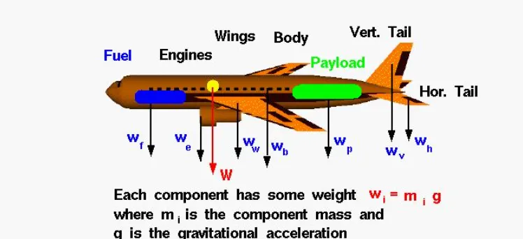
2)Difference between ground speed and Air speed:
*Ground speed:
-They are the airplane speed which is related to the ground.
-They are the speed which determines how fast the airplane will reach the detination.
-They are the calculated by summing up the airspeed and windspeed.
*Air speed:
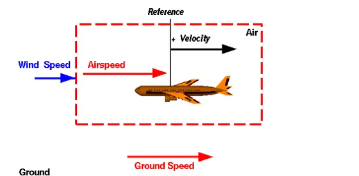
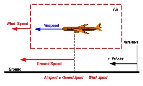
-It refers to the speed which is relative to air it is flying in.
-They determine whether there is enough airflow around an aircraft to make it lift.
-They are independent of ground speed.
The above two daigram relative velocity with respect to aircraft reference and ground reference.
-Here wind speed is the vector difference between ground and air speed.On a perfect still day the wind speed is zero and it is equal to the ground speed.
-If the measured air speed is greater than the observed ground speed the wind speed becomes positive.
3)Why it is not recommended to use aircraft engines to move it on the gorund at airport?
-Generally most of the airplane can move itself in reverse manner by making use of reverse thrust technology.But in most of the practical it is not possible because when airplanes start using reverse thrust it will consume lot of fuels as well as causes lot of noise and also hazardous
4)To learn about take off power,tyre design, rolling resistance,tyre pressure,brake froce when landing?
-Take off is the phase of the flight in which an aeroplane leaves ground and becomes airbone.For lighter aircraft full power is given durong take off where as on the other hand large cargo carriers aircraft make use of less power during take off inorder to inrease the life span of engine,reduce maintenance cost,reduce engine heat and also for a smooth take off flight.
-The forces involved during take off are the following:
T=Thrust froce pushes the aircraft in forward dierection on the runway.
D-Drag force resist the forward motion of the aircraft.
F-Rolling resistance force when wheel comes in contact with the gorund during landing and take off.
-During take off on the runway the imbalance froce will cause an acceleration along the runway and it is given by the formula:
F 721 =T-D
-Now when the pilot is ready to take off the aircraft will accelerated to a speed which would be given by aircraft controlling department. Then after take off the flight will be elevated to a certain angle and hieght.then it will be made to stabilies in an equilibrium manner.
-Here safe speed or rotational speed is defined as Vr which act as a critical factor for determining take off performance For safety reasons Vr is usually determined as 1.1"Vstall(lowest speed that aircraft can be flown before the air starts to seperate from the wings when the angle of attract becomes too great.
-Vstall can be calculated by using a formula given:
5. Take off power, tyre design, rolling resistance, tyre pressure, brake forces when landing
a.Take off Performance:
Take off performance can be predicted using a simple measure of the acceleration the aircraft along the runway based on force equilibrium.
The forces involved will be.
T-Thrust of propulsion system pushing aircraft along runway.
D-Aerodynamic Drag of vehicle resisting the aircraft motion.
F-Rolling resistance friction due to the contact of wheels or skids on the ground.
During take-off run the imbalance in these forces will produce an acceleration along the runway.
dv/dt = T-D-F/m
The procedure for take-off will be that the vehicle will accelerate until it reaches a safe initial flying speed. The pilot can then rotate the vehicle to an attitude to produce climb lift and it will ascend from the ground. The determination of this safe flying speed or rotation speed. V. is a critical factor in determining take-off performance.
For safety reasons VR is usually determined as being 1.1 x VSTALL
VSTALL: is the lowest speed that the aircraft can be flown before the airflow starts to separate from wings as the angle of attack becomes too great. The wing is assumed in this case to be in take-off configuration or "clean".
clear all
%Inputs
c=0.002%Rolling resistance coefficient
m=linspace (200, 25000, 2000) % Weight g=9.81 �celeration of gravity
u=0.6% friction coefficient A=linspace(50, 100, 2000) %area of planes
v=2 % velocity
Cd-0.8 %Drag Coefficient
F1-c*m*g %Rolling resistance force
F2=u*g*m%Friction force F3=0.5*A*1.2*Cd* (v)^2
Ft=F1+F2+F3
plot (m, Ft)
title('Tractive Force vs Weight of planes')
xlabel('Weight of planes (kg)')
ylabel('Tractive Force') axis ([0 20000 20000])
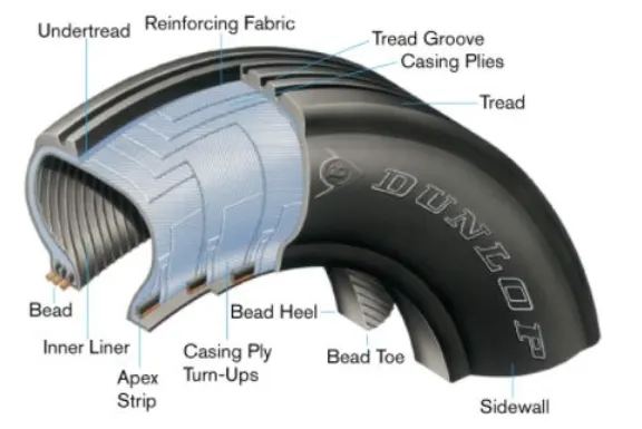
b.Tyre Design of aircrafts:
When it comes to safety, tyres are one of the most important components of aircraft. They help to absorb the shock of landing and provide cushioning. It also provides the necessary traction for braking and stopping of an aircraft.
An aircraft tyre is designed to withstand extremely heavy loads while landing, take off, taxing and parking. The number of wheels required for aircraft increases with the weight of the aircraft, as the weight of the aeroplane needs to be distributed more evenly
Carcass plies are used to form the tire. They are sometimes called casing plies. An aircraft tyre is constructed for the purpose it serves.
Unlike an automobile or truck tyre, it does not have to carry a load for a long period of continuous operation. However, an aircraft tyre absorbs the high impact loads of landing and also it's operating at high speeds for a short time when required.
Retreading-Retreading is methods of restoring a worn tyre by renewing the tread area or by renewing the tread area plus one or both sidewalls. Repairs are included in the tyre retreading process.
Load Rating-Load rating is the maximum permissible load at a specified inflation pressure.
Ply Rating-Ply Rating is used to identify the maximum recommended load rating and inflation pressure for a specified tyre, it is an index of tyre strength.
Speed Rating-The speed rating is the maximum takeoff speed to which the tyre has been tested.
Skid Depth-Skid depth is the distance between the tread surface and the deepest groove as measured in the mould
Aircraft tyres must have an approved speed and load rating and have sufficient clearance when retracted through landing gear to allow for tyre growth. Tyre growth is the increase in the size of the tyre due to centrifugal forces at high speed.
Rolling Resistance:
The rolling resistance can be expressed as
F, CW
(1)
where
F, rolling resistance or rolling friction (N, lb)
c=rolling resistance coefficient - dimensionless (coefficient of rolling friction - CRF)
W=mag
- normal force - or weight of the body (N, lb)
m = mass of body (kg, lb)
ag" acceleration of gravity (9.81 m/s2, 32.174 ft/s²)
The force to move an air plane on an absolute flat runway with no wind at constant low speed is equal to the rolling resistance between the plane and the tarmac.
The rolling resistance for the air plane can be calculated as
F₁ - cm, a
(1)
where
F₁-rolling resistance (N. lb)
crolling resistance coefficient
m, rolling mass (kg, lb)
a acceleration of gravity (9.81 m/s2)
The friction force for the puller can be calculated to
ere to search
title('Tractive Force vs Weight of planes') ylabel('Tractive Force') axis ( [0 20000 20000])
Consider the powertrain with the following specifications:
Vehicle Drive: 2.0 HP, 36 VDC Traction Motor mated with High-Efficiency Helical Gear Dana Axle Assembly
Batteries: Six 6 VDC, 190 AMP-HR Batteries (6 hr rate), wired in series.
Vehicle Speed, Loaded: 3.6 mph/5.8 kph
Lift Cradle Capacity: 1,500 lbs / 680 kg
Now this can be represented in simulink in the following manner: