Week - 4
Q1. Implement control logic of a “washing machine” using Stateflow as per given sequence:
Objectives:
- If the power supply is available, the system gets activated
- If the Water supply is not available, stop the process & indicate through LED
- Soaking time should be 200s followed by Washing time of 100s.
- Then rinsing happens for next 20s & dryer runs for 50s
After all the processes have completed turn on the finished LED
Process:
Working principle of the proposed Washing Machine:
In the process of washing machine ,a spinning motor spins around 600-1600rpm in the mixture of detergent and water ,to wash the clothes .in the total process there are several process as follows:
- Fetching of water:in the process, the water is fetched inside from the outsource.
- Soaking(200s):In this process ,the mixture of water and detergent is soaked
- Washing(100s)
- rinsing(20s)
- Drying(50s)
Here is the simulink model
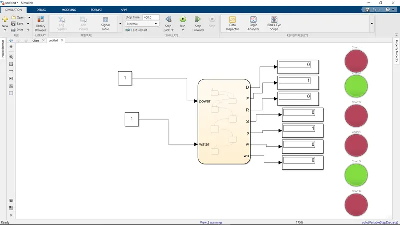
Description: first,its starts with the input block ,If the power supply is available, the system gets activated
then,at the time of system running, If the Water supply is not available, stop the process & indicate through LED
after that,Soaking time should be 200s followed by Washing time of 100s.
Then rinsing happens for next 20s & dryer runs for 50s
After all the processes have completed turn on the finished LED
in the model,
it starts with,Fetching of water:in the process, the water is fetched inside from the outsource.
secondly,Soaking(200s):In this process ,the mixture of water and detergent is soaked
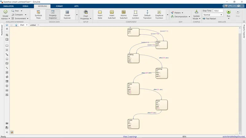
after that,Washing(100s) is done , after washing rinsing(20s) is done,then atlast Drying(50s) process has been done, after that finish occure with the indication of the Led.
the use of the chart block opens the door for the possibility of the simulation on the simulink.
Subsystem
Q2
Make a Simulink chart for the “Gear shift” logic as per below conditions:
Speed Range(kmph) Gear
0 to 15 1
16 to 25 2
26 to 40 3
41 to 60 4
Above 61 5
Give speed input while the simulation is running & display the gear number.
The simulink model
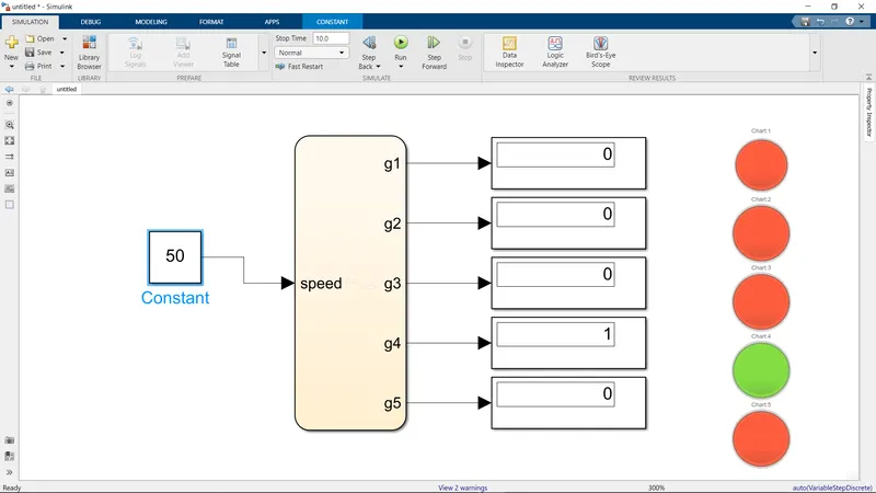
Description: On the above system,The Gear box consists of 5 gear trnsmission,which will activated in the different speed condition as follows
Speed Range(kmph) Gear
0 to 15 1
16 to 25 2
26 to 40
41 to 60 4
Above 61 5
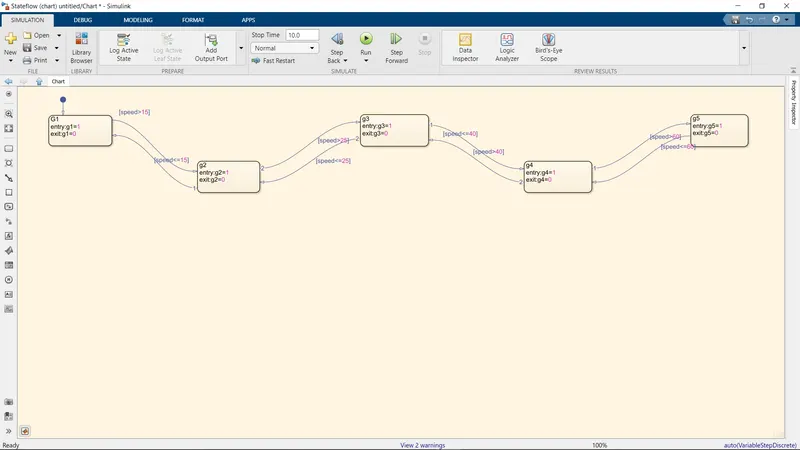
as the speed increasing,the shifting of gear also increase accordingly.
,the use of the chart block opens the door for the possibility of the simulation on the simulink.
The sub system
Conclusion:From the above challanges ,i abled to learn the state flow of the simulink.