Week -2
I. Aim of the challange: Make a Simulink model of Doorbell using solenoid block with the following details:
Q.2 Make a Simulink model of Doorbell using solenoid block
Answer:
In the above arrangement, when the switch is closed the electromagnet receives electrical power from the battery and
pulls the metal arm to hit the bell producing sound.
Create a situation where the switch is closed for 2 seconds and then released.
Observe the physical movement of the plunger.
assuming the left parameters.
Theory:
The circuit of the bell(door) using a solenoid block is as shown on the above picture.
whenever we tap on the switch ,we close the circuit which leads the electric current to flow in the circuit. then the electromagnet gets charged and acts like magnet due to which it pulls near metal clip in front of it.as the metal starts to move towards the magnet ,the extended part of the metal clip hits the gong and succeed to produce a sound,which refers to the sound of the bell.
- The simulation of door bell
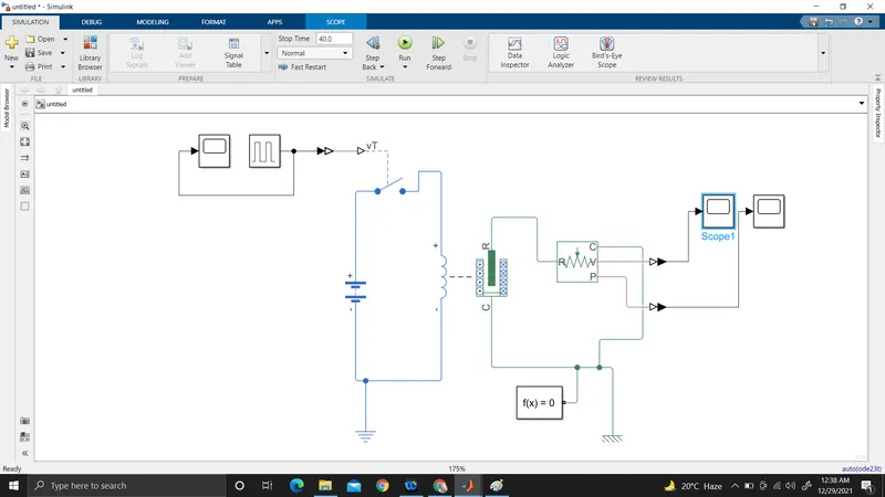
Description:
1. pulse generator:This block generates the square wave pulses at the specified regular intervals depending on the waveform parameters,pulsewidth,Amplitude,period,phase delay,determines the shape of the wave.
2. Simulink-ps convertor:it converts the simulink input signl to physical signal.
3.Scope: used to display the signal generated by the pulse generator.
4.spst switch:represents a single pole single throw switch controlled by extrernal control signal that is vt.
5.Battery:used as power source.
6.Electrical reference:acts as electrical ground.
7.Solenoid:Used as electromagnet utilizes to produce the sound whenever it hits the metal.
8.Solver Configuration:used to specify the solver parameters that our model needs before we can begin the simulation.
9. Ideal Translational Motion sensor: used as the motion sensor in mechanical translational systems.
10.Ps-simulink converter:used to converts input physical signal to simulink output signal.
Working principle of the model:
1. pulse generator generates an input signal of 1unit amplitude,4sec periode having 50% pulse with 2-sec delay for the model.
2.The input signal connected with the simulink ps converter which converts the simulink signal to a physical signal
3.The signal goes to the spst switch to turn it on and off during the operation.
4. Depending on he pulse,switching is occured in the circuit , and closes the path to flow the current .
5.Depending on the switching,the solenoid is magnetize and demagnetize and produce the sound.
6.A mechanical translational reference is connected to port R of the solenoid to know the position and velocity of the plunger.
7.To store the position and velocity ps converter converts the physical signal to the simulink signal ,then we store the footage of the record using the scope.
Results:
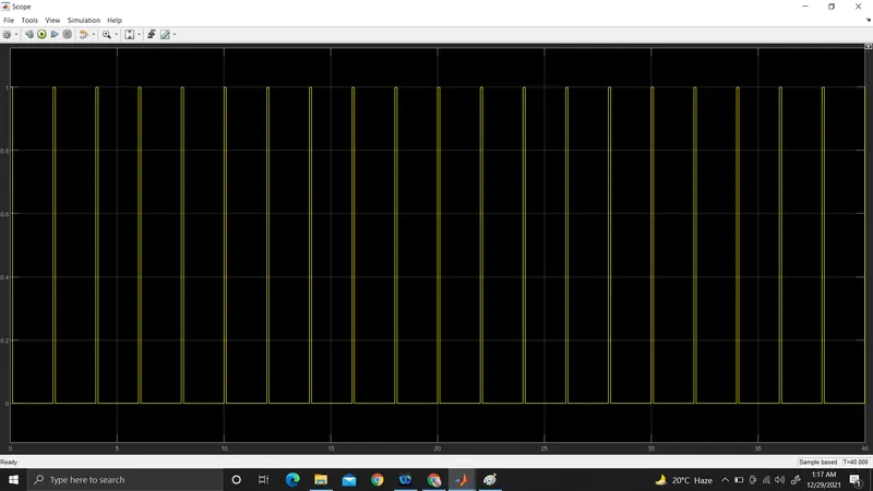
Pulse vs Time
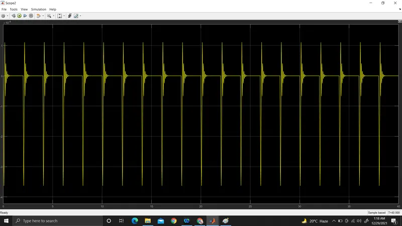
Position vs Time
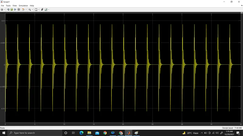
Velocity vs Time
Q.2
Use a thermistor to sense the temperature of a heater & turn on or turn off the fan as per the below conditions:
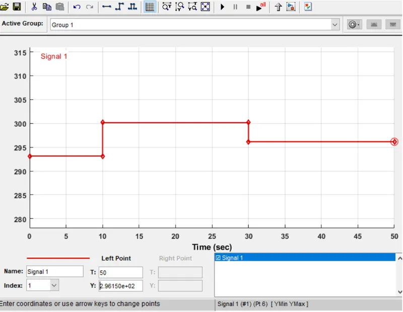
Temperature source: 20 °C from 0 to 10 seconds, 27 °C from 10 to 30 seconds, 23 °C from 30 to 50 seconds
Fan conditions: ON if the temperature above 25 °C, OFF otherwise
Solution
Theory:
The thermistor is a type of resistor whose resistance is totally depending on the temperature,than the normal standard resistor.The word is the addition in between thermal and resistor,are widely used as inrush cureent limiters.property is depending on the -ve temperature coefficient (ntc).
Following is the simulink simulation model for using a thermistor to sense the temperature of the heater,depending on that ,system is turn on and turn off the fan as per the condition.
Simulink mode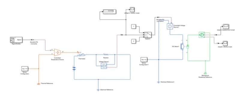
Description:
1.The system for temperature sensing using the thermistor requires heating source as signal controlled temperature source,signal builder ,some switches,dc motor,voltage regulation system,scope to to realize the signal.
2. The system starts with the heater (controlled temperature source ),the temperature of the heater is depending on the condition in terms of the signal builder.
the signal builder gives the signal ,which faithfully obeyed by the pre defined time period.
3.signal builder follows this criteria 20 °C from 0 to 10 seconds, 27 °C from 10 to 30 seconds, 23 °C from 30 to 50 seconds.
Like that>
4.The output of the heating element or heater is fed to the thermal input port of the thermistor ,and other two ports are connected to electrical source (+ve and Ground).
5. The fan switched on only above 25degree celcius and above.and the volage regulator or sensor senses in series with the thermister ,that controls the switch.the voltage sensor is connected in the parallel nabber to the resistor for the specific time cycle.output of the sensor is connected to the display,scope witch block via simulink converter.
6.Depending on the thresshold value can be obtained from the voltage sensor,for the 25 degree celcius,The value must in between 23 and 27 ,0.012 from the voltage graph,the condition is to threshold ,at this conditiion switch is closed when the threshold value is reached.
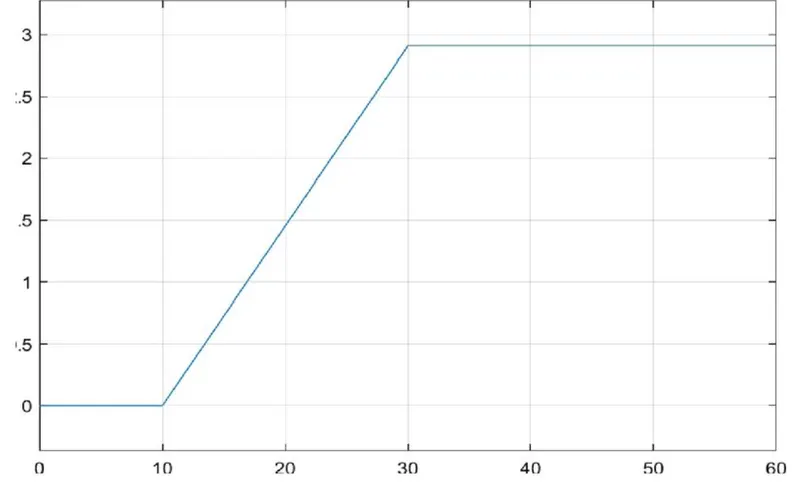
depending on the value the two way switch is open and closed or turn on and turn off respectively.
7.The dc motor(fan) is connected to the switch which indicates the fan is turn on and off depending on the state of the switch.
8.The simulation is run for the 50 seconds.
This is the graph for switch to fan on and off.
Conclusion:The model for the doorbell and temperature sensor to turn on and off the fan was created successfully.