Project-1: Powertrain for aircraft in runways
1.
aim: to Search and list out the total weight of various types of aircrafts
explanation:
The different terms represent different weights or masses1. For each flight, the weights are taken into account for several reasons.
A brief description about these is below:
manufactured empty weight(MEW)
Also called Manufacturer's Weight Empty (MWE) or Licensed Empty Weight
It is the weight of the aircraft "as built" and includes the weight of the structure, power plant, furnishings, installations, systems and other equipment that are considered an integral part of an aircraft.
This excludes any baggage, passengers, or usable fuel
zero fuel weight(ZFW)
This is the total weight of the airplane and all its contents (including unusable fuel), but excluding the total weight of the usable fuel on board.
As a flight progresses and fuel is consumed, the total weight of the airplane reduces, but the ZFW remains constant.
Maximum zero fuel weight (MZFW) is the maximum weight allowed before usable fuel and other specified usable agents (engine injection fluid, and other consumable propulsion agents) are loaded.
operating empty weight(OEW)
(Roughly equivalent to basic empty weight on light aircraft)
It is the basic weight of an aircraft including the crew, all fluids necessary for operation such as engine oil, engine coolant, water, unusable fuel and all operator items and equipment required for flight but excluding usable fuel and the payload.
payload
It is the carrying capacity of an aircraft. It includes cargo, people, extra fuel. In the case of a commercial airliner, it may refer only to revenue-generating cargo or paying passengers.
maximum takeoff weight (MTOW)
This is the maximum weight at which the pilot of the aircraft is allowed to attempt to take off3.
regulated takeoff weight (RTOW)
Depending on different factors (e.g. flap setting, altitude, air temperature, length of runway), RTOW or maximum permissible takeoff weight varies for each takeoff. It can never be higher than MTOW. More information is on
maximum loading weight (MLW)
This maximum weight at which an aircraft is permitted to land.
maximum ramp weight(MRW)
also called maximum taxi weight (MTW)
It is the maximum weight authorized for maneuvering (taxiing or towing) an aircraft on the ground.
air gross weight
It is the total aircraft weight at any moment during the flight or ground operation. This decreases during flight due to fuel and oil consumption.
list of the total weight of various types of aircrafts:
| Aircraft | Empty Weight | Max Fuel Weight | Max Cargo Weight | Max Gross Takeoff Weight |
|---|---|---|---|---|
| Antanov AN-225 | 628,000 lbs 285,000 kg |
661,400 lbs 300,000 kg |
417,000 lbs 190,000 kg |
1,411,000 lbs 640,000 kg |
| Airbus A380-800 | 611,000 lbs 277,000 kg |
560,000 lbs 254,000 kg |
185,000 lbs 84,000 kg |
1,268,000 lbs 575,000 kg |
| Boeing 747-800 | 485,300 lbs 220,100 kg |
427,400 lbs 194,000 kg |
295,000 lbs 134,000 kg |
987,000 lbs 447,700 kg |
| Airbus A340-500 | 370,000 lbs 168,000 kg |
386,300 lbs 175,000 kg |
119,000 lbs 54,000 kg |
820,000 lbs 372,000 kg |
| Boeing 777-300ER | 370,000 lbs 168,000 kg | 320,800 lbs 145,500 kg | 148,000 lbs 67,100 kg |
776,000 lbs 352,000 kg |
| Boeing 787-10 | 299,000 lbs 135,500 kg | 223,500 lbs 101,500 kg |
126,300 lbs 57,300 kg | 560,000 lbs 254,000 kg |
| Boeing 737-900 | 98,500 lbs 44,700 kg |
53,100 lbs 24,000 kg |
44,600 lbs 20,200 kg |
187,000 lbs 85,000 kg |
| Airbus A320-100 | 93,900 lbs 42,600 kg |
48,700 lbs 22,100 kg |
44,000 lbs 20,000 kg |
150,000 lbs 68,000 kg |
| Embraer 190 | 63,500 lbs 28,800 kg |
28,600 lbs 13,000 kg |
28,800 lbs 13,100 kg |
106,000 lbs 48,000 kg |
| Gulfstream G650 | 54,000 lbs 24,500 kg | 48,200 lbs 21,900 kg | 6,500 lbs 3,000 kg |
100,000 lbs 45,200 kg |
| Bombardier CRJ900 | 48,160 lbs 21,850 kg | 19,600 lbs 8,900 kg | 6,075 lbs 2,760 kg | 80,500 lbs 36,500 kg |
| Bombardier Q400 | 39,300 lbs 17,800 kg |
11,700 lbs 5,300 kg |
18,700 lbs 8,500 kg |
62,000 lbs 28,000 kg |
| Learjet 75 | 13,900 lbs 6,300 kg | 6,060 lbs 2,750 kg |
2,900 lbs 1,300 kg |
21,500 lbs 9,700 kg |
| Cessna Citation CJ4 | 10,300 lbs 4,700 kg | 5,800 lbs 2,650 kg |
2,200 lbs 1,000 kg | 17,200 lbs 7,800 kg |
| Beechcraft King Air B100 | 7,100 lbs 3,200 kg | 3,200 lbs 1,450 kg |
4,150 lbs 1,900 kg |
12,000 lbs 5,400 kg |
| Diamond DA50 RG | 3,200 lbs 1,450 kg |
340 lbs 155 lbs |
1,250 lbs 560 kg |
4,400 lbs 2,000 kg |
| Beechcraft Bonanza G36 | 2,500 lbs 1,150 kg | 450 lbs 200 kg |
850 lbs 385 kg |
3,660 lbs 1,660 kg |
| Cessna 206H | 2,200 lbs 990 kg |
520 lbs 235 kg |
1,150 lbs 520 kg |
3,600 lbs 1,630 kg |
| Sirrus SR22 | 2,250 lbs 1,000 kg | 485 lbs 220 kg |
950 lbs 430 kg |
3,600 lbs 1,630 kg |
| Cessna 172R | 1,700 lbs 770 kg |
380 lbs 170 kg |
560 lbs 255 kg |
2,425 lbs 1,100 kg |
2.
aim: to find that is there any difference between ground speed and air speed
explanation:
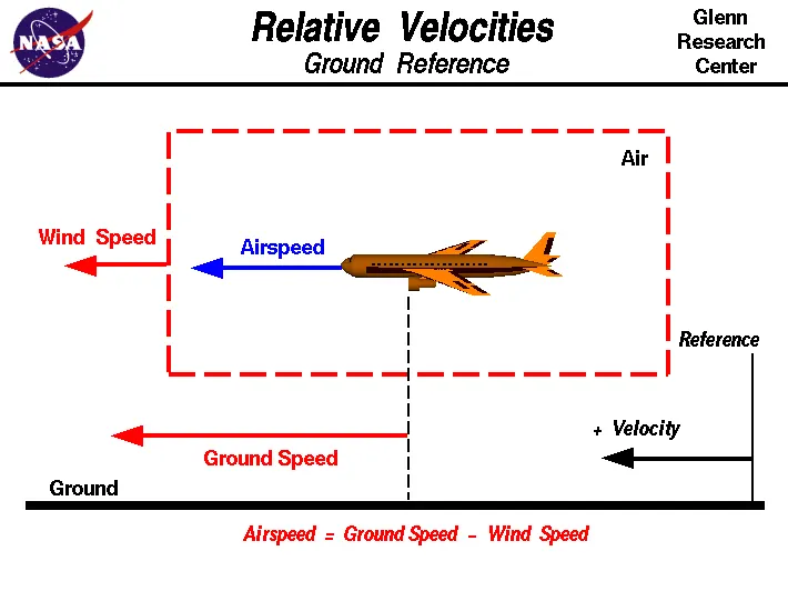
Wind Speed
For a reference point picked on the ground, the air moves relative to the reference point at the wind speed. Notice that the wind speed is a vector quantity and has both a magnitude and a direction. Direction is important. A 20 mph wind from the west is different from a 20 mph wind from the east. The wind has components in all three primary directions (north-south, east-west, and up-down). In this figure, we are considering only velocities along the aircraft's flight path. A positive velocity is defined to be in the direction of the aircraft's motion. We are neglecting cross winds which occur perpendicular to the flight path but parallel to the ground, and updrafts and down drafts which occur perpendicular to the ground.
Ground Speed
For a reference point picked on the ground, the aircraft moves relative to the reference point at the ground speed. Ground speed is also a vector quantity so a comparison of the ground speed to the wind speed must be done according to rules for vector comparisons
Airspeed
The important quantity in the generation of lift is the relative velocity between the object and the air, which is called the airspeed. Airspeed cannot be directly measured from a ground position, but must be computed from the ground speed and the wind speed. Airspeed is the vector differences between the ground speed and the wind speed.
Airspeed = Ground Speed - Wind Speed
On a perfectly still day, the airspeed is equal to the ground speed. But if the wind is blowing in the same direction that the aircraft is moving, the airspeed will be less than the ground speed.
3.
aim: to find why is it not recommended to use aircraft engine power to move it on the ground at Airport
explaination:
The forward movement of an aircraft, usually with engines off, using the power of a specialised ground vehicle attached to or supporting the nose landing gear. It may occur for the movement of both in service and out of service aircraft. This will affect the promulgation of procedures and the required qualification for those occupying the flight crew seats on the aircraft during the manoeuvre. As part of out of service repositioning of aircraft supervised by maintenance personnel, it may follow the push back from a nose-in gate of an empty aircraft with engines off.
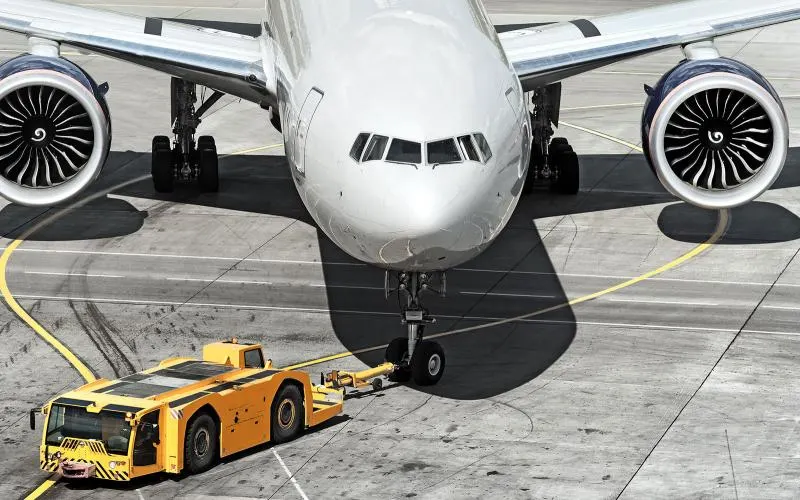
- Inadequate awareness of aircraft dimensions and turning arcs by the ground crew towing
- Lack of clearance between horizontal stabilisers of a towed ‘T’ tail aircraft when it is turning in proximity to another similar ‘T’ tail type.
- Failure to keep towed aircraft on the taxiway centreline or other taxi guidance line.
- Inadvertent or otherwise inappropriate brake application during towing by personnel ‘riding the brakes’a collision with a moving aircraft taking off or landing on an active runway whether or not the aircraft under tow has a valid ATC runway occupancy clearance.
- impact damage to another, usually stationary and unoccupied, aircraft caused by undetected relatively minor impact which is then not detected prior to either damaged aircraft departing on a flight.
4.
aim: to know how an aircraft is pushed to runway when its ready to take off
explaination:
Take-Off
Takeoff is the phase of flight in which an aircraft goes through a transition from moving along the ground (taxiing) to flying in the air, usually starting on a runway. Usually the engines are run at full power during takeoff. Following the taxi motion, the aircraft stops at the starting line of the runway. Before takeoff, the engines, particularly piston engines, are routinely run up at high power to check for engine-related problems. This makes a consid- erable noise. When the pilot releases the brakes, the aircraft starts accelerating rapidly until the necessary speed for take-off is achieved.
The takeoff speed required varies with air den- sity, aircraft weight, and aircraft configuration (flap and/or slat position, as applicable). Air density is affected by factors such as field ele- vation and air temperature.
Taxiing :
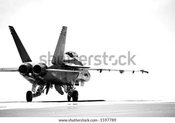
Taxiing refers to the movement of an aircraft on the ground, under its own power. The aircraft moves on wheels. An airplane uses taxiways to taxi from one place on an airport to another; for example, when moving from a terminal to the runway.
The aircrafts always moves on the ground following the yellow lines, to avoid any collision with the surrounding buildings, vehicles or other aircrafts. The taxiing motion has a speed limit. Before making a turn, the pilot reduces the speed further to prevent tire skids. Just like cars, there is a certain list of priorities during taxiing. The aircrafts that are landing or taking off have higher priority. The other aircrafts have to wait for these aircrafts before they start or continue taxiing.
5.
aim: to learn about take off power, tyre design, rolling resistance, tyre pressure, brake forces when landing.
explaination:
take off power:
• An airplane is motionless at the end of a runway. This is denoted by location O. The pilot releases the brakes and pushes the throttle to maximum takeoff power, and the airplane accelerates down the runway. At some distance from its starting point, the airplane lifts into the air. The distance the airplane cover along the runway before it lifts into the air is called the ground roll (sg). The total takeoff distance also includes the extra distance covered over the ground after the airplane is airborne but before it clears an obstacle of 50 ft for military aircraft and 35 ft for commercial aircraft. This is denoted by sa. The sum of sg and sa is the total takeoff distance.
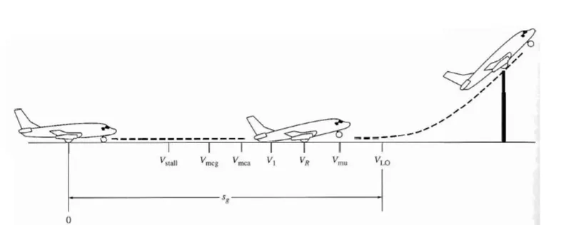
• As the airplane accelerates from zero velocity, at some point it will reach the stalling velocity VStall
• The airplane continues to accelerate until it reaches the minimum control speed on the ground, Vmcg. This is the minimum velocity at which enough aerodynamic force can be generated on the vertical fin with rudder deflection while the airplane is still rolling along the ground to produce a yawing moment sufficient to counteract that produced when there is an engine failure for a multiengine aircraft.
• If the airplane were in the air (without the landing gear in contact with the ground), the minimum speed required for yaw control in case of engine failure is slightly greater than Vmcg This velocity is called the minirnum control speed in the air, Vmca
• The airplane continues to accelerate until it reaches the decision speed, V1. This is the speed at which the pilot can successfully continue takeoff even though an engine failure (in a multiengine aircraft) would occur at this point. If an engine
fails before V1 is achieved, the takeoff must be stopped. If an engine fail after V1 is reached, the takeoff has to be completed.
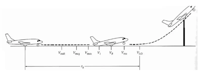
• The airplane continues to accelerate until the takeoff rotational speed, VR is achieved. At this velocity, the pilot initiates by elevator deflection a rotation of the airplane in order to increase the angle ofattack and to overcome the weight. Attention should be paid not to stall.
• the angle of attack necessary to overcome the weight may not be achievable because the tail may drag the ground. If the rotation of the airplane is limited by ground clearance for the tail, the airplane must continue to accelerate while rolling along the ground after rotation is achieved. This speed is called the minimum unstick speed, denoted by Vus.
• For increased safety, the angle of attack after rotation is slightly less than the maximum allowable by tail clearance, and the airplane continues to accelerate to a slightly higher velocity, called the lift off speed, denoted by VLO. This is the point at which the airplane actually lifts off the ground. The total distance covered along the
ground to this point is the ground roll sg.
• Generally VLO=1.1 Vstall In addition to the familiar forces of thrust, weight, lift, and drag, there is a rolling
resistance R, caused by friction between the tires and the ground.
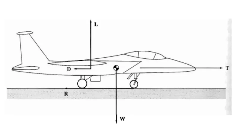
`m* ((dv)/(dt)) = T -D -R`
`R = mur (W-L)`
`m* ((dv)/(dt)) = T -D -mur(W -L)``
tyre design:
An aircraft tire or tyre is designed to withstand extremely heavy loads for short durations.The number of tires required for aircraft increases with the weight of the aircraft, as the weight of the airplane needs to be distributed more evenly. Aircraft tire tread patterns are designed to facilitate stability in high crosswind conditions, to channel water away to prevent hydroplaning, and for braking effect.
radial ply tire construction:
A typical radial tire is illustrated With their rigid belt, they provide increased landings and reduced rolling resistance. They have fewer components in their construction and are lighter than similarly sized bias ply tires. Components that differ from bias-ply construction as follows:
Overlay: A layer of reinforcing rubber coated fabric placed on top of the belts to aid in high speed operation.
Belt Plies: A composite structure that stiffens the tread area for increased landings. The belt plies increase the tire strength in the tread area.
Casing Plies: As in bias-ply tires, the casing plies are layers of rubber-coated fabric. However, unlike those in bias plies that run at opposite angles to one another, radial plies run radially from bead to bead.
Chippers: The chippers are layers of rubber-coated fabric applied at diagonal angles that improve the durability of the tire in the bead area.
bias ply tyre construction:
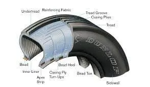
A cutaway of a typical bias-ply tire is shown in Figure 1. Bias-ply tires are popular choices for aircraft tires because of their durability and retreadability. The tire construction consists of the following components:
Tread: The tread is made of rubber mixed with other additives to obtain the desired level of toughness, durability, and resistance to wear. The tread pattern is designed to aircraft operational requirements, with the ribbed tread design used widely due to its good traction under varying runway conditions.
Sidewall: The sidewall is a protective layer of rubber that covers the outer casing ply. It extends from the tread edge to the bead area.
Tread Reinforcing Ply: One or more layers of fabric that strengthens and stabilizes the tread area for high-speed operation. It also serves as a reference for the buffing process when tires are retreaded.
Buff Line Cushion: The buff line cushion is made of rubber compound to enhance the adhesion between the tread reinforcing ply and the breakers or casing plies. It is of sufficient thickness to allow for the removal of the old tread when the tire is retreaded.
Breakers: Breakers are reinforcing plies of rubber-coated fabric placed under the buff line cushion to protect casing plies and strengthen and stabilize the tread area. They are considered an integral part of the casing construction.
Casing Plies: Alternate layers of rubber-coated fabric (running at opposite angles to one another) provide the strength of the tire.
Wire Beads: Hoops of high tensile strength steel wire that anchor the casing plies and provide a firm mounting surface on the wheel. The outer edge of the bead that fits against the wheel flange is called the bead heel. The inner bead edge is called the bead toe.
Apex Strip: A wedge of rubber affixed to the top of the bead bundle.
Flippers: Layers of rubberized fabric that help anchor the bead wires to the casing and improve the durability of the tire.
Ply Turnups: The casing plies are anchored by wrapping them around the wire beads, thus forming the ply turnups.
Chafer: A protective layer of rubber and/or fabric located between the casing plies and wheel to minimize chafing.
Liner: In tubeless tires, the liner is a layer of low permeability rubber that acts as a built-in tube and restricts gas from diffusing into the casing plies. In tube-type tires, a thinner liner is used to prevent tube chafing against the inside ply.
rolling resistance :
Rolling resistance is one of the forces that act to oppose the motion of a cyclist. It is caused mainly because of deformation of the tyre and can be understood by thinking about:
- energy losses due to heat (hysteresis)
- the forces pushing on the tyre.
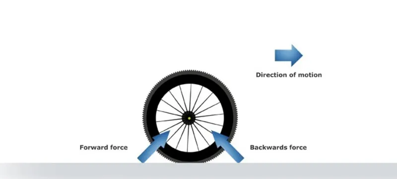
This equation is used to calculate the force of rolling resistance from each tyre:
FRR = CRR x weight
- FRR is the rolling resistance force.
- CRR is the coefficient of rolling resistance (a number used to rate each tyre at a given pressure),
- weight is the force due to gravity being exerted on each tyre (= mass (kilograms) x 9.8).
This equation shows that speed does not affect the force due to rolling resistance. The type of tyre and the mass of the bike plus rider are the only two variables.
tyre pressure:
Aircraft tires generally operate at high pressures, up to 200 psi (14 bar; 1,400 kPa) for airliners, and even higher for business jets. The main landing gear on the Concorde was typically inflated to 232 psi (16.0 bar), whilst its tail bumper gear tires were as high as 294 psi (20.3 bar).
Aircraft tires are amazing when you think about it. The typical airliner tire can handle a 38-ton load. It can meet the ground 500 times before needing a re-tread, a refresh it can take on seven times in its life.
A Boeing 777 uses 14 tires, Airbus' A380 carries 22, and the demands 32. The key to their remarkable durability is maximizing the air pressure, says Lee Bartholomew, lead test engineer for Michelin Aircraft Tires. The high-flying rubber is typically inflated to 200 psi, roughly six times what you put in an automobile tire, and the tires on an F-16 fighter are pumped to 320 psi.
brake forces:
wing spoilers
Many airplanes use wing spoilers to assist with braking when landing. Not to be confused with ailerons, spoilers are extendable flaps on the ends of an airplane’s wings. Pilots can raise the spoilers to decelerate the airplane as it approaches the runway. And even while on the runway, pilots will typically leave the wing spoilers raised. Raised wing spoilers create drag, which essentially slows down the airplane so that it’s able to brake more quickly.
disc brakes:
In addition to wing spoilers, airplanes use disc brakes. Airplane disc brakes are similar to the braking system in automobiles. They consist of a pair of calipers that, when engaged, squeeze pads against the rotors of an airplane’s landing gear.
Disc brakes are designed to remain static at all times. In other words, they don’t rotate with the wheels of an airplane’s landing gear. As the wheels turn, the disc brakes will remain static and stationary. They are a vital component of an airplane’s braking system because they are designed to apply pressure to the airplane’s wheels. Disc brakes will squeeze the wheels, thereby slowing down the speed at which they spin. In turn, this reduces the speed of the airplane so that it can come to a complete stop on the runway.
reverse thrust:
Finally, many jet airplanes use reverse thrust to assist with braking during landings. Reverse thrust is a feature in jet engine airplanes that, as the name suggests, involves the reversal of the engines’ thrust. When flying, the thrust is projected out the rear of an airplane’s engines. When landing, however, pilots may use the reverse thrust feature. Reverse thrust changes the direction of the engines’ thrust. Rather than projecting out the rear, the thrust will be projected out the front. This reversal of thrust provides deceleration that allows airplanes to slow down more quickly when landing.
6.
aim:. With necessary assumptions, calculate the force and power required to push / pull an aircraft by a towing vehicle.
calculation:
consider an aircraft AIRBUS A380
total load of the air bus = 575000 kg
1. rolling resistance
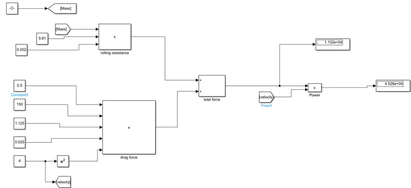
rolling resistance `Fr = mu *m*g`
`mu =`cofficient of rolling rsistance = 0.002
m = 575000 kg
g = 9.81
`Fr =`0.002*575000*9.81
= 11.281 kN
rolling resistance of the aircraft is more when compared to the towing vehicle so rolling resistance of towing vehicle is neglected
2. drag force
drag force `Fd = 0.5 * rho *Cd *A*V^2`
drag cofficient Cd = 0.025
area A= 150 `m^2`
velocity = 4 `m/sec`
density `rho`= 1.125 Kg/`m^3`
`Fd = 0.5*1.125*150*4*4` = 33.75 N
hill climbing and acceleration forces are neglected
power = force*velocity
= 11.281*4
= 45.26 Kw
minimum power required for towing vehicle is 45.26 Kw at a speed of 4 m/s
aim: Develop the model for the calculated force and power using Simulink
explaination:
simulink block diagram:
result:
using the above simulink blocks mentioned above we can calculate the power and force required for towing vehicle in order to move the aircraft
7.
aim: to design an electric powertrain with type of motor, it’s power rating, and energy requirement to fulfill aircraft towing application in Simulink. Estimate the duty cycle range to control the aircraft speed from zero to highest. Make all required assumptions. Prepare a table of assumed parameters. Draw a block diagram of powertrain
explaination:
block diagram:
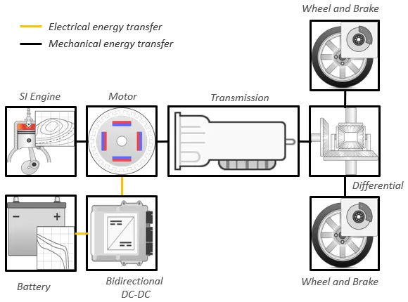
an aeropalne pushback vehicle is required to move aeroplane from aeroplane terminals and tow them across the air feild from routine maintance.the pushback maintance vehicle must be able to generate a large towing force but it also have high speed to travel quickly between pushback operation
let wheel radius be = 0.5 m
maximum torque on wheels
T = wheel radius * force
=0.5 *11950
= 59750 Nm
let us assume an induction motor of 300kw
duty cycle = `(output power )/( input power)` = 260.48/300 = 88.26 %
B.
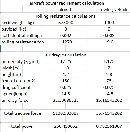
aim: Design the parameters in excel sheet.