Project-1: Powertrain for aircraft in runways
1. Search and list out the total weight of various types of aircrafts.
| Type | MTOW [kg] | MLW [tonnes] | TOR [m] | LR [m] | ICAO category | FAA category |
|---|---|---|---|---|---|---|
| Antonov An-225 | 640,000 | 591.7 | 3500 | Heavy | Super | |
| Scaled Composites Model 351 Stratolaunch | 589,670 | 3660 | Heavy | Super | ||
| Airbus A380-800[1][2][3] | 575,000 | 394 | 3100 | 1930 | Super | Super |
| Boeing 747-8F | 447,700 | 346.091 | 3100 | 1800 | Heavy | Heavy |
| Boeing 747-8 | 443,613 | 306.175 | 3100 | Heavy | Heavy | |
| Boeing 747-400ER | 412,770 | 295.742 | 3090 | Heavy | Heavy | |
| Antonov An-124-100M | 405,060 | 330 | 2520 | 900 | Heavy | Heavy |
| Boeing 747-400 | 396,900 | 295.742 | 3018 | 2179 | Heavy | Heavy |
| Lockheed C-5 Galaxy[4][5][6] | 381,000 | 288.417 | 2530 | 1494 | Heavy | Heavy |
| Boeing 747-200[7] | 377,840 | 285.700 | 3338 | 2109 | Heavy | Heavy |
| Boeing 747-300[7] | 377,840 | 260.320 | 3222 | 1905 | Heavy | Heavy |
| Airbus A340-500[8] | 371,950 | 240 | 3050 | 2010 | Heavy | Heavy |
| Airbus A340-600[8] | 367,400 | 256 | 3100 | 2100 | Heavy | Heavy |
| Boeing 777F | 347,800 | 260.816 | 2830 | Heavy | Heavy | |
| Airbus A330-900 | 352,000 | 251.5 | 3100 | Heavy | Heavy | |
| Boeing 777-300ER | 351,800 | 251.29 | 3100 | Heavy | Heavy | |
| Boeing 777-200LR | 347,450 | 223.168 | 3000 | Heavy | Heavy | |
| Boeing 747-100[7] | 340,200 | 265.300 | Heavy | Heavy | ||
| Airbus A350-1000 | 308,000 | 233.5 | Heavy | Heavy | ||
| Boeing 777-300 | 299,370 | 237.683 | 3380 | Heavy | Heavy | |
| Boeing 777-200ER | 297,550 | 213.00 | 3380 | 1550 | Heavy | Heavy |
| Airbus A340-300[8][9] | 276,700 | 190 | 3000 | 1926 | Heavy | Heavy |
| McDonnell Douglas MD-11 | 273,300 | 185 | 2990 | 1890 | Heavy | Heavy |
| Airbus A350-900 | 270,000 | 175 | 2670 | 1860 | Heavy | Heavy |
| Ilyushin Il-96M | 270,000 | 195.04 | 3115 | 2118 | Heavy | Heavy |
| McDonnell Douglas DC-10 | 256,280 | 183 | 2990 | 1890 | Heavy | Heavy |
| Boeing 787-9[10] | 254,000 | 192.777 | 2900 | Heavy | Heavy | |
| Boeing 787-10[10] | 254,000 | 201.849 | Heavy | Heavy | ||
| Airbus A340-200[8][11] | 253,500 | 181 | 2990 | Heavy | Heavy | |
| Ilyushin IL-96-300 | 250,000 | 175 | 2600 | 1980 | Heavy | Heavy |
| Airbus A330-300[12][13] | 242,000 | 185 | 2500 | 1750 | Heavy | Heavy |
| Airbus A330-200[12][13] | 242,000 | 180 | 2220 | 1750 | Heavy | Heavy |
| Lockheed L-1011-500 | 231,300 | 166.92 | 2636 | Heavy | Heavy | |
| Boeing 787-8[10] | 228,000 | 172.365 | 3300 | 1695 | Heavy | Heavy |
| Lockheed L-1011-200 | 211,400 | Heavy | Heavy | |||
| Ilyushin IL-86 | 208,000 | 175 | Heavy | Heavy | ||
| Boeing 767-400ER | 204,000 | 158.758 | 3414 | Heavy | Heavy | |
| Airbus A300-600R[14] | 192,000 | 140 | 2385 | 1555 | Heavy | Heavy |
| Boeing 767-300ER | 187,000 | 136.08 | 2713 | 1676 | Heavy | Heavy |
| Concorde | 185,000 | 111.1 | 3440 | 2220 | Heavy | Heavy |
| Airbus A300-600[14] | 163,000 | 138 | 2324 | 1536 | Heavy | Heavy |
| Boeing 767-300 | 159,000 | 136.078 | 2713 | 1676 | Heavy | Heavy |
| Airbus A310-300[14] | 157,000 | 124 | 2290 | 1490 | Heavy | Heavy |
| Vickers VC10 | 152,000 | 151.9 | Heavy | Heavy | ||
| Boeing 707-320B[15] | 151,000 | 97.5 | Heavy | Heavy | ||
| Boeing 707-320C[15] | 151,000 | 112.1 | Heavy | Heavy | ||
| Douglas DC-8-61 | 147,000 | Heavy | Heavy | |||
| Airbus A310-200[14] | 142,000 | 123 | 1860 | 1480 | Heavy | Heavy |
| Airbus A400M | 141,000 | 122 | 980 | 770 | Heavy | Heavy |
| Douglas DC-8-32 | 140,000 | Heavy | Heavy | |||
| Douglas DC-8-51 | 125,000 | Medium | Large | |||
| Boeing 757-300 | 124,000 | 101.6 | 2550 | 1750 | Medium | Large |
| Boeing 707-120B[15] | 117,000 | 86.3 | Medium | Large | ||
| Boeing 757-200 | 116,000 | 89.9 | 2347 | 1555 | Medium | Large |
| Boeing 720B[16] | 106,000 | 79.5 | Medium | Large | ||
| Boeing 720[16] | 104,000 | 79.5 | Medium | Large | ||
| Tupolev Tu-154M | 104,000 | 80 | Medium | Large | ||
| Tupolev Tu-204SM | 104,000 | 87.5 | 2250 | Medium | Large | |
| Convair 880 | 87,500 | Medium | Large | |||
| Boeing 737-900 | 85,000 | 66.36 | 2500 | 1704 | Medium | Large |
| Boeing 737-900ER | 85,000 | 71.35 | 2804 | 1829 | Medium | Large |
| Boeing 727-200 Advanced[17] | 84,000 | 70.1 | Medium | Large | ||
| Airbus A321-100[18] | 83,000 | 77.8 | 2200 | 1540 | Medium | Large |
| Boeing 737-800 | 79,000 | 65.32 | 2308 | 1634 | Medium | Large |
| Boeing 727-200[17] | 78,000 | 68.1 | Medium | Large | ||
| McDonnell-Douglas MD-83 | 73,000 | 63.28 | Medium | Large | ||
| Boeing 727-100[17] | 72,500 | 62.4 | Medium | Large | ||
| Boeing 727-100C[17] | 72,500 | 62.4 | Medium | Large | ||
| McDonnell-Douglas MD-90-30 | 71,000 | 64.41 | 2165 | 1520 | Medium | Large |
| de Havilland Comet 4 | 70,700 | Medium | Large | |||
| Boeing 737-700 | 70,000 | 58.06 | 1921 | 1415 | Medium | Large |
| Airbus A320-100[18] | 68,000 | 66 | 1955 | 1490 | Medium | Large |
| Boeing 737-400 | 68,000 | 54.9 | 2540 | 1540 | Medium | Large |
| de Havilland Comet 3 | 68,000 | Medium | Large | |||
| Boeing 377 | 67,000 | Medium | Large | |||
| Boeing 737-600 | 66,000 | 54.66 | 1796 | 1340 | Medium | Large |
| Airbus A220-300 | 65,000 | 57.61 | 1890 | 1494 | Medium | Large |
| Hawker Siddeley Trident 2E | 65,000 | Medium | Large | |||
| Airbus A319[18] | 64,000 | 62.5 | 1850 | 1470 | Medium | Large |
| Boeing 737-300 | 63,000 | 51.7 | 1939 | 1396 | Medium | Large |
| Boeing 737-500 | 60,000 | 49.9 | 1832 | 1360 | Medium | Large |
| Airbus A220-100 | 59,000 | 50.80 | 1463 | 1356 | Medium | Large |
| Airbus A318[18] | 59,000 | 57.5 | 1375 | 1340 | Medium | Large |
| Boeing 717-200HGW | 55,000 | 47.174 | 1950 | Medium | Large | |
| Douglas DC-7 | 55,000 | Medium | Large | |||
| de Havilland Comet 2 | 54,000 | Medium | Large | |||
| Boeing 717-200BGW | 50,000 | 46.265 | 1950 | Medium | Large | |
| de Havilland Comet 1 | 50,000 | Medium | Large | |||
| Douglas DC-6A | 48,600 | Medium | Large | |||
| Douglas DC-6B | 48,500 | Medium | Large | |||
| Embraer 190[19] | 48,000 | 43 | 2056 | 1323 | Medium | Large |
| Caravelle III | 46,000 | Medium | Large | |||
| Fokker 100 | 46,000 | 39.95 | 1621 | 1350 | Medium | Large |
| Douglas DC-6 | 44,000 | Medium | Large | |||
| Avro RJ-85 | 42,000 | 36.74 | Medium | Large | ||
| Handley Page Hermes | 39,000 | Medium | Large | |||
| Embraer 175[20] | 37,500 | 32.8 | 2244 | 1304 | Medium | Large |
| Bombardier CRJ900[21] | 36,500 | 33.345 | 1778 | 1596 | Medium | Large |
| Embraer 170[22] | 36,000 | 32.8 | 1644 | 1274 | Medium | Large |
| Bombardier CRJ700 | 33,000 | 30.39 | 1564 | 1478 | Medium | Large |
| Douglas DC-4 | 33,000 | Medium | Large | |||
| Vickers Viscount 800 | 30,400 | Medium | Large | |||
| Bombardier Q400 | 28,000 | 28.01 | 1219 | 1295 | Medium | Large |
| Bombardier CRJ200 | 23,000 | 21.319 | 1918 | 1479 | Medium | Large |
| ATR 72-600 | 22,800 | 22.35 | 1333 | 914 | Medium | Large |
| Saab 2000 | 22,800 | 21.5 | 1300 | Medium | Large | |
| Embraer ERJ 145 | 22,000 | 19.3 | 2270 | 1380 | Medium | Large |
| ATR 42-500 | 18,600 | 18.3 | 1165 | 1126 | Medium | Small |
| Saab 340 | 13,150 | 12.930 | 1300 | 1030 | Medium | Small |
| Embraer 120 Brasilia | 11,500 | 11.25 | 1560 | 1380 | Medium | Small |
| BAe Jetstream 41 | 10,890 | 10.570 | 1493 | 826 | Medium | Small |
| Learjet 75[23] | 9,752 | 8.709 | 1353 | 811 | Medium | Small |
| Pilatus PC-24[24] | 8,300 | 7.665 | 893 | 724 | Medium | Small |
| Embraer Phenom 300[25] | 8,150 | 7.65 | 956 | 677 | Medium | Small |
| Beechcraft 1900D | 7,765 | 7.605 | 1036 | 853 | Medium | Small |
| Cessna Citation CJ4[26] | 7,761 | 7.103 | 1039 | 896 | Medium | Small |
| de Havilland Hercules | 7,000 | Medium | Small | |||
| Embraer Phenom 100 | 4,800 | 4.43 | 975 | 741 | Light | Small |
2. Is there any difference between ground speed and air speed?
While ground speed is the airplane’s speed relative to the surface of the Earth, airspeed – at least true airspeed – is its speed relative to the air it is flying in.
Below, I will explain the two types of speed in more detail, as well as talk about the four types of airspeed that are commonly used.
As mentioned above, true airspeed is simply the speed at which an aircraft is moving relative to the air it is flying in. As such, it’s also the speed at which the air is flowing around the aircraft’s wings.
Ground speed, on the other hand, is the aircraft’s speed relative to the ground. One thing that should be noted here is that it’s its horizontal rather than vertical speed – an aircraft climbing completely vertically would have a ground speed of zero.
In other words, while airspeed is what determines whether there is enough airflow around an aircraft to make it fly, ground speed is what determines how fast an aircraft will get to its destination.
The relationship between airspeed and ground speed is fairly simple. Ground speed is simply the sum of airspeed and wind speed.
If the aircraft is flying in the same direction as the wind is blowing, the aircraft experiences tailwind, and its ground speed is higher than its airspeed. On the other hand, if the wind is blowing against the direction the aircraft is traveling in, the aircraft experiences headwind, and its ground speed is lower than its airspeed.
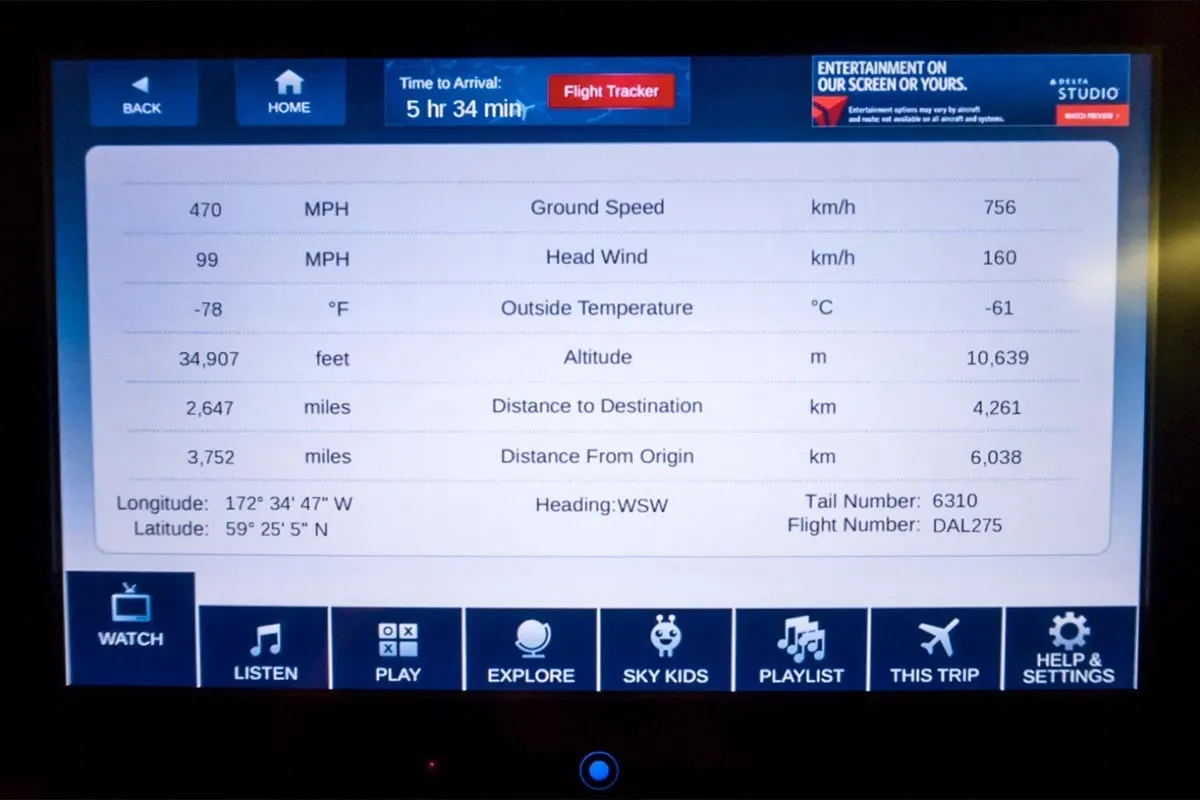
To give you an actual example, imagine an aircraft that cruises at an airspeed of 500 miles per hour that has to cover a ground distance of 2,000 miles.
If there is no wind at all, then both the aircraft’s airspeed and ground speed would be the same 500 miles per hour, and the aircraft would reach its destination in four hours.
If there was a 100 miles per hour headwind – wind blowing against the aircraft’s direction of travel – the aircraft would still be traveling at an airspeed of 500 miles per hour. However, its ground speed would be just 400 miles per hour (100 miles per hour slower than its airspeed). And as such, it would take the aircraft five hours to reach its destinations.
Finally, if there was a 100 miles per hour tailwind – wind blowing in the same direction as the aircraft’s travel – the aircraft would still be traveling at an airspeed of 500 miles per hour, but its ground speed would be 100 miles faster. And, at 600 miles an hour, the aircraft would reach its destination in just three hours and twenty minutes.
The above is the reason why some flights go “out of their way” to avoid headwinds or catch tailwinds. And, why some flights might appear to be traveling at “supersonic speeds,” even though their airspeed – the speed that would actually matter in determining whether or not the flight truly is supersonic – is subsonic.
3. Why is it not recommended to use aircraft engine power to move it on the ground at Airport?
We are assuming passenger commuter aircraft and large airliners. Aircraft move using their own engine power all the time on the airport apron and taxiways under their own power to go towards runways and after landing taxi to their assigned gate.
The only time they use external assistance is to pushback from the gate. Large turbofan aircraft need help to reverse via a pushback tractor. The engines are turned on after the pushback is complete and the aircraft can move forward under It’s own power.
To be accurate, some aircraft can reverse using a variable pitch prop or thrust reversing on turbofans but generally reversing is done via pushback tractors. Blasting jet reversers blows debris In the crowded gate area creating foreign object damage hazard for adjacent aircraft, gate equipment or terminal waiting area glass windows.
4. How an aircraft is pushed to runway when its ready to take off?

For smaller aircraft, the pushback tug doesn’t require a massive amount of power. They utilize the weight of the tug, sometimes up to 60 tons, to ensure that the wheels don’t just spin on the tarmac. “The small ones have enough power to push and tow an aircraft up to a 757,” says a pushback driver at Munich International Airport. “The functionality is pretty simple. We connect a tow-bar at the aircraft first, then at the tug.”
It takes skill to push an aircraft back using these types of tug. “You have two steering axis here at the nose gear and at the tug where the tow-bar is connected,” he said. “So when you steer right, the nose of the aircraft goes opposite.”
However, with bigger aircraft, tug designers ran into a problem. Even with a 60-ton tug, there isn’t enough weight to stop the tug wheels spinning. To get round this problem, they needed something to weigh the tug down. Something like the weight of a 560-ton A380.
Tow-barless tugs clamp around the nose wheel of the aircraft and lift it up, thus utilizing the weight of the aircraft to provide the traction for its wheels. “We need between 40 and 90 seconds to connect the tug with the aircraft and lift it up,” he added. “The Goldhofer AST-1X is the Godfather of all tugs because at 32 tons, its 16-liter 700 HP engine is enough to push all heavies easily. We use that tug for 767 up to A380.”
Engines Provide the Thrust
Once the tug has disconnected and the engines are running, the pilots call ATC for their clearance to taxi to the departure runway. They will then be issued with a series of taxiways, which will eventually take them to the departure point. At smaller airports, this may just be one taxiway. At larger airfields it could be a number of taxiways, broken up into segments to give way to other aircraft. It’s worth noting that aircraft don’t ‘taxi down the runway’. They taxi on taxiways, hence the name, taxiway. (Sometimes aircraft do have to taxi on the runway, but this is relatively infrequent. So, for the case of this article, I decided to keep it simple.)
If this was your car, you’d put the gear into drive or first gear and press the accelerator. This would inject fuel into the engine and provide power to turn the wheels and off you’d go. However, aircraft wheels aren’t connected to the engines in any way. When the pilots squeeze the thrust levers forwards, the thrust generated from the engines pushes the aircraft forwards. The wheels merely turn under this forward power allowing the aircraft to move.
5. Learn about take off power, tyre design, rolling resistance, tyre pressure, brake forces when landing.
Take off power
Takeoff is the phase of flightin which an aerospace vehicle leaves the ground and becomes airborne. For aircraft traveling vertically, this is known as liftoff.
For aircraft that take off horizontally, this usually involves starting with a transition from moving along the ground on arunway For some specialized fixed-wing aircraft aircraft such as the no runway is needed.
For light aircraft usually full power is used during takeoff. Large (airliner) aircraft may use a for takeoff, where less than full power is applied in order to prolong engine life, reduce maintenance costs and reduce noise emissions. In some emergency cases, the power used can then be increased to increase the aircraft's performance. Before takeoff, the engines, particularly , are routinely run up at high power to check for engine-related problems. The aircraft is permitted to accelerate to rotation speed (often referred to as Vr). The term is used because the aircraft pivots around the axis of its main while still on the ground, usually because of gentle manipulation of the to make or facilitate this change in (once proper air displacement occurs under / over the wings, an aircraft will lift off on its own; controls are to ease that in).
The nose is raised to a nominal 5–15° nose up attitude to increase lift from the and effect liftoff. For most aircraft, attempting a takeoff without a pitch-up would require cruise speeds while still on the runway.
Fixed-wing aircraft designed for high-speed operation (such as commercial have difficulty generating enough lift at the low speeds encountered during takeoff. These are therefore fitted with often including and usually which increase the and often area of the wing, making it more effective at low speed, thus creating more lift. These are deployed from the wing before takeoff, and retracted during the climb. They can also be deployed at other times, such as before landing.
The speeds needed for takeoff are relative to the motion of the air ). will reduce the ground speed needed for takeoff, as there is a greater flow of air over the wings. Typical takeoff air speeds for jetliners are in the range of 240–285 (130–154 149– have even lower takeoff speeds. For a given aircraft, the takeoff speed is usually dependent on the aircraft weight; the heavier the weight, the greater the speed needed.Some aircraft are specifically designed for which they achieve by becoming airborne at very low speeds.
On take-off, in order to position the aircraft to a safe height away from terrain and obstacles (i.e. a flight path of maximum height and minimum ground distance desired), the engine thrust is set to a high ‘take-off power’ setting (although this is not necessarily full power) and the aircraft attitude is pitched up to maintain a specific speed (usually in the region of V2 + 15kts). Once the ‘safe height’ is reached the engine thrust can therefore be reduced to a more appropriate (i.e. efficient) setting and the aircraft flight path can be changed to a more appropriate (i.e. efficient) flight path.
In order to achieve that described above and also to provide minimum noise disturbance to the area surrounding the airport, regulatory procedures require aircraft to fly one of the two profiles given below during every departure. The aerodrome briefing pages will state which one of the two profiles is to be flown at each particular airport:
- At 1,500ft aal reduce thrust to climb power and accelerate the aircraft towards 250 knots, retracting flaps and slats.
- At 1,500ft aal reduce thrust to climb power maintaining V2 + 15kts. At 3,000ft accelerate the aircraft.
Operator’s SOPs must therefore enable the above procedures to be flown and, as such, controllers will witness flight crews performing certain actions and verbal SOP callouts during the initial climb in order to accomplish this. Aircraft that have highly automated systems will perform the thrust reduction and acceleration manoeuvre with minimal input from the flight crew. Note that the flight crew must input the required data into the FMS during the pre-flight procedure to enable such aircraft to accomplish this. In such aircraft it may be the case that the only physical action required by the flight crew is to move the flap lever, the remainder of the actions are of a monitoring nature to ensure that the correct Flight Mode Annunciator (FMA) modes engage and that the aircraft physically performs the manoeuvre correctly. In less automated aircraft it will require an increased amount of button pushing, knob turning and verbal calls to perform the thrust reduction and acceleration manoeuvre. During the initial climb, at the heights stated above, the thrust reduction and acceleration procedure therefore gives rise to issues regarding increased workload in the flight deck.
Tyre Design
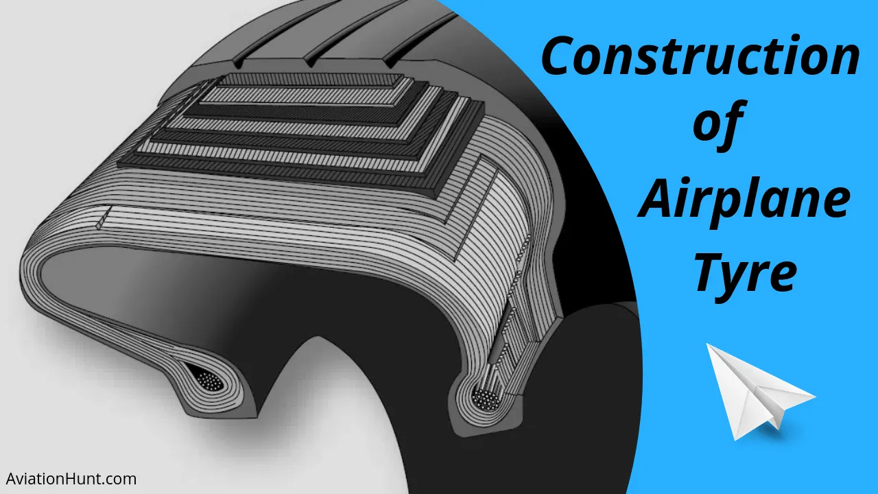
Many aviation technicians are not aware of the critical design factors of aircraft tyre in use today. I will discuss step by step, but first, I would like to ask the importance of tyre in aircraft.
When it comes to safety tyres are one of the most important components of aircraft. They help to absorb the shock of landing and provide cushioning. It also provides the necessary traction for braking and stopping of an aircraft.
An aircraft tyre is designed to withstand extremely heavy loads while landing, take off, taxing, and parking. The number of wheels required for aircraft increases with the weight of the aircraft, as the weight of the aeroplane needs to be distributed more evenly.
A Boeing 737NG & 737MAX uses 6 wheels, Boeing 787 uses 10 wheels, Boeing 777 uses 14 wheels and Airbus A380 uses 22 wheels. Aircraft tyres work under extreme conditions, carrying up to 340 tons and accelerating at over 250 km/hour at takeoff, in addition to enduring varied environmental stress when in flight and taxiing.
Carcass plies are used to form the tire. They are sometimes called casing plies. An aircraft tyre is constructed for the purpose it serves.
- They support the weight of an aircraft while it is on the ground.
- It also provides the necessary traction for braking and stopping of an aeroplane.
- Tyre also helps to absorb the shock of landing and provide cushioning the roughness of takeoff, roll-out, and taxi operations.
Unlike an automobile or truck tyre, it does not have to carry a load for a long period of continuous operation. However, an aircraft tyre absorbs the high impact loads of landing, and also it’s operating at high speeds for a short time when required.
Let’s go through some technical aspects of the tyre.
Retreading – Retreading is methods of restoring a worn tyre by renewing the tread area or by renewing the tread area plus one or both sidewalls. Repairs are included in the tyre retreading process.
Load Rating – Load rating is the maximum permissible load at a specified inflation pressure.
Ply Rating – Ply Rating is used to identify the maximum recommended load rating and inflation pressure for a specified tyre. It is an index of tyre strength.
Speed Rating – The speed rating is the maximum takeoff speed to which the tyre has been tested.
Skid Depth – Skid depth is the distance between the tread surface and the deepest groove as measured in the mould.
Aircraft tyres must have an approved speed and load rating and have sufficient clearance when retracted through landing gear to allow for tyre growth. Tyre growth is the increase in the size of the tyre due to centrifugal forces at high speed.
Tubeless tyres are more advantageous over tube-type. There is no longer the use of tube-type tyre in recent aviation. Nowadays all airliners are using tubeless tyres. Tubeless that are meant to be used without a tube has the word TUBELESS on the sidewall of the tyre.
Rolling Resistance:
Force resisting the motion when body rolls on the surface.
Rolling Resistance coefficient:
is the indication of how great the rolling resistance is for a given normal force between the wheel and the surface upon which its rolling .
equation is Fr=UrN
Ur= coefficient of rolling friction
Fr= is the resistive force of rolling friction
N is the normal or perpendicular force of the wheel on a surface.
Tyre Pressure
An aircraft tire or tyre is designed to withstand extremely heavy loads for short durations. The number of tires required for aircraft increases with the weight of the aircraft, as the weight of the airplane needs to be distributed more evenly. Aircraft tire tread patterns are designed to facilitate stability in high conditions, to channel water away to prevent and for braking effect.
Aircraft tires also include (which are assembled on the inside of the wheels), designed to melt at a certain temperature. Tires often overheat if maximum braking is applied during an aborted takeoff or an The fuses provide a safer failure mode that prevents tire explosions by deflating in a controlled manner, thus minimizing damage to aircraft and objects in the surrounding environment.
Aircraft tires are usually inflated with nitrogen to minimize expansion and contraction from extreme changes in ambient temperature and pressure experienced during flight. Dry nitrogen expands at the same rate as other dry atmospheric gases (normal air is about 80% nitrogen), but common compressed air sources may contain moisture, which increases the expansion rate with temperature.
The requirement that an inert gas, such as nitrogen, be used instead of air for inflation of tires on certain transport category airplanes was prompted by at least three cases in which the oxygen in air-filled tires had combined with volatile gases given off by a severely overheated tire and exploded upon reaching autoignition temp. The use of an inert gas for tire inflation eliminates the possibility of tire explosion.
Brake forces when landing
The brake disks themselves are made up of two parts. Firstly, there are the rotors. These are connected to the wheel by drive tabs (in the video below they are the black rectangles on the rotor disks). As these drive tabs are in contact with the inside of the wheel, they spin at the same speed. Depending on the brake manufacturer, there are either four or five of these rotors on each brake assembly.
The second part of the disks are the stators. These sit around each rotor and are fixed in place and thus don’t move. As the wheel turns, the rotors spin round inside the stators.
When the brakes are applied, the four EBAs apply pressure to the first stator. This in turn squeezes the stationary stators up against the spinning rotors and it’s this friction which slows the wheel down. https://www.youtube.com/watch?v=n0nXiQPwHE8
Anti-skid protection
When landing on slippery runways, there’s a chance that the wheels may start to skid as the brakes are applied. To stop this from happening and to maintain maximum effective braking, each wheel has anti-skid protection.
Using a variety of sources to determine the aircraft speed, the brake units know how fast the wheels should be spinning. If that speed drops significantly, it’s because the current brake pressure on that wheel is too great and the wheel is just skidding over the surface.
In this situation, the anti-skid system automatically reduces the braking on that wheel to a point where the skid stops before reapplying the pressure. All this is done in a fraction of a second.
Autobrake
Pressing on the brakes is pretty straight forward when at low speed. However, when we’re landing in strong winds, it can be a little tricky. We need to use our feet on the rudder pedals to line the nose of the aircraft up with the runway centerline at the last moment. Then, whilst holding that position, slide our feet up to press the toe brakes. Really not very easy when moving at 160 mph.
To help us get the braking underway as soon as we touch down, we have the autobrake system.This provides automatic braking at a preselected rate as soon as the aircraft senses that it is on the ground. It also provides full braking pressure in the case of a rejected takeoff if the speed is above 85 knots (98 mph).
Brake temperature indication
With friction comes heat. As a result, each brake unit displays its temperature on the wheel synoptic page in the flight deck. Here, numerical values relating to brake temperature are shown next to each wheel. A value of 0-4.9 is in the normal range. When a temperature becomes 5.0 or above, an advisory message is displayed to the pilots.
Should the brakes become too hot, there’s a chance that the heat transferred to the wheels could cause the tires to explode. To stop this from happening, when a certain temperature is reached, fuse plugs in the tires melt. This allows the air to be released safely and slowly deflate the tires.
Parking brake
Every so often we need to engage the brakes and keep them on. This is particularly useful on long taxis to the runway and obviously . The park brake is set by fully pressing down both toe brakes and pulling the parking brake lever up. With this set, we can then release the pressure from the pedals. To release, we just press the brake pedals again.
In addition to the brakes, there are two other systems which help slow the aircraft down on landing. The spoilers and the reverse thrust.
Spoilers
Have you noticed the large panels on the top of the wings raise up on touch down? These are the called the spoilers as they literally spoil the airflow over the wing. This dumps any remaining lift the wings are generating, allowing the wheels to take all the weight and achieve maximum efficiency from the brakes.
Reverse thrust
The final part of the braking process comes from reverse thrust. Just after we have touched down, we pull two levers on top of the thrust levers to engage the reverse thrust, a sort of “reverse gear” for jet engines.
This causes to deploy and a door in the side of the engine to slide backward. The air which normally leaves the engine out the back is deflected forward by the blockers and out through the door.
6. A. With necessary assumptions, calculate the force and power required to push / pull an aircraft by a towing vehicle.
Let the assumptions be
Weight of the Aircraft (Airbus A-380) = 575000kg
Rolling Resistance Coefficient of an aircraft tire(urr ) = 0.004
Wight of the Towing Tractor = 50000kg
Rolling Resistance Coefficient of Towing Vehicle(urr ) = 0.001
Then,
Rolling Resistance Force of Tow Tractor =urrxm.g=0.49KN
Rolling Resistance Force of aircraft =22.56KN
Total Rolling Resistance Force = Rolling Resistance Force of aircraft + Towing Tractor = 0.49 + 22.56
Total Rolling Resistance Force = 23.05KN
Air Drag Force.
The Aerodynamic Drag is given by the following expression.Where,
Fad=1/2 p.A.V^2.Cd
p= Density of Air Medium
A = Frontal Area Of the Vehicle which strike the Air
V = Velocity with the vehicle moves
Cd= Coefficient of Dragwhich varies different shapes of the frontal area.
Calculation:
Let us assume
The Velocity of the Aircraft while Towing = 30KMPH = 8.33m/s
Dnsity of Air medium(p ) = 1.225
The Frontal area of the Aircraft = 20
The Coefficient of Drag of the Aircraft = 0.026
Air drag force = 0.5*rho*A*V^2*Cd = 0.022KN
The Air Drag Force of the Aircraft = 0.022KN
Therefore the total force that the motor needs to overcome = Rolling Resistance of the aircraft + Drad Force Acting on the Aircraft hence the total forces acting =23.05 + 0.022
The Total Force that the Motor needs to overcome in order to push/pull the Aircraft = 23.07KN
Power Required
The power required by the motor is given by the velocity with which the towing operation takes place.
The average speed of push/pull = 20 kmph = 5.5m/s
Power required by the motor = Total Force*Velocity = 23.07*5.5
Power Required by The Motor = 126.8kw
The torque output of the towing tractor can also be calculated by the below steps.μrr
Fte=TxG/r
Fte= The Total Tractive Force(Rolling resistance force + Air drag force)
T = Torque Output
r = Radius of Tire
G = Gear Ratio
For Heavy Duty Towing Tractor we Assume,
G = 11(for delivering high torque)
r = 25inches = 0.635m
The Torque required to Push/Pull for the above stated condition = 1.327 KNm
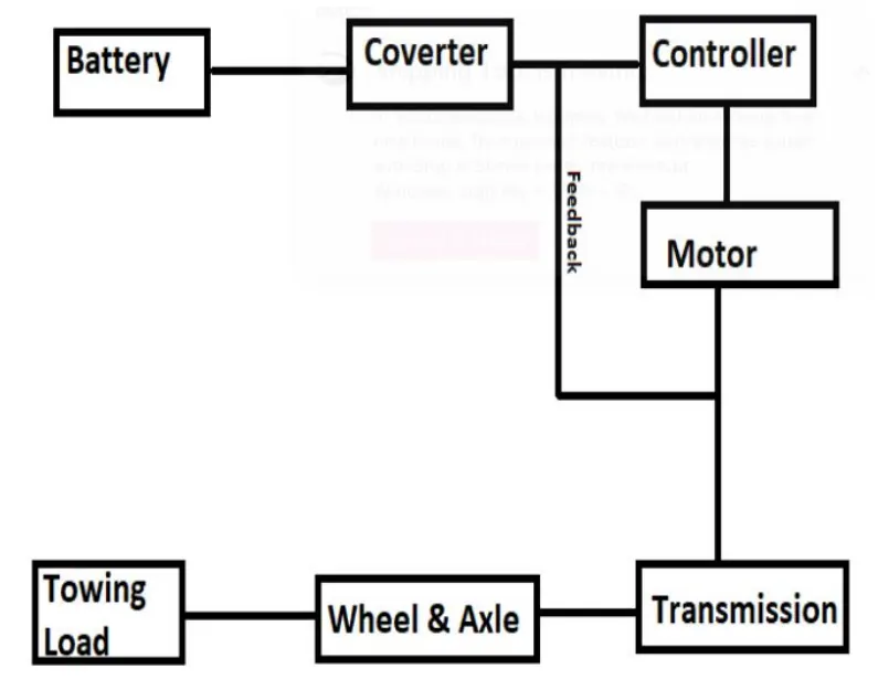
7. Design an electric powertrain with type of motor, it’s power rating, and energy requirement to fulfill aircraft towing application. Estimate the duty cycle range to control the aircraft speed from zero to highest. Make all required assumptions. Prepare a table of assumed parameters. Draw a block diagram of
powertrain.
The parameters assumed for designing this vehicle is taken from online references
1. Weight of the Aircraft 575000 kg
2. Weight of the Towing Tractor 50000 kg
3. Rolling Resistance Coefficient of Aircraft 0.004
4. Rolling Resistance Coefficient of Towing Tractor 0.001
5. The velocity of the Aircraft while Towing 8.33 m/s
6. Density of Air medium(rho) 1.225 kg/m^3
7. The Frontal area of the Aircraft 20 m^2
8. The Coefficient of Drag of the Aircraft 0.026
9. Towing Tractor Gear ratio(G- for high torque output) 11
10. Towing Tractor tyre radus(r) 0.635 m
11. Operational time of the Towing for one cycle 0.33 Hour
12. The Battery Armature Voltage 350 V
13. The Battery Armature Current 350 A
14. The Motor Terminal Voltage for full power output 630 V @ motor terminals
15. Power converters used Bidirectional DC-DC Boost Converter
16. The maximum duty ratio for acieving full power 70%
Assuming the operational time of the Towing Truck is around 20 minuts for one cycle
20 minuts = 0.33 hour
Energy(kwh) = power(kw)*Time(h) = 162.8*0.33
Energy= 41.8kwh
Therefore the battery must be able to store the energy 41.8 kwh and should deliver the energy throughout the run time in order for the motor to produce the 1.32
KNm of torque instantaneously. Thus the storage of energy in batteries with high performance Ultracapacitors are selected to fulfill the required power deliver.
Motor Selection:
Here we have selected a BLDC Motor type that has a power rating of 126.8kw and with the gear ratio and the transmission it should be able to deliver 1.32KNm of
torque instantaneously.
The Battery Armature Voltage (V) 350 V
The Battery Armature Current (A) 350 A
Power Converter:
A boost converter (step-up converter) is a DC-to-DC power converter that steps up voltage (while stepping down current) from its input (supply) to its output
(load). It is a class of switched-mode power supply (SMPS) containing at least two semiconductors (a diode and a transistor) and at least one energy storage
element: a capacitor, inductor, or the two in combination. To reduce voltage ripple, filters made of capacitors (sometimes in combination with inductors) are
normally added to such a converter's output (load-side filter) and input (supply-side filter).
Speed Control of the Vehicle:
The Electric Vehicle uses power from the battery source to drive the motor and then further to drive the wheels in order to move the vehicle. The speed and
torque generated from the motor is very important to drive the vehicle as per the driver's desire. If we connect the battery directly to the motor the motor will spin
with a speed and torque characteristics which will be based on the full power of the battery voltage. We does not require full power in all the driving conditions so we need to adopt a power controller between the bettery and the motor so that the motor speed may be controlled by the driver to drive the vehicle as desired.
For controlling the vehicle power we use the soft switching operation technique here. The amount of power can be controlled by changing the Duty Cycle value.
Considering the losses we take 70% of the duty cycle to deliver the maximum power of the motor.
Motor Terminal Voltage = Armature Voltage * Duty Cycle = 900*0.7
With 70% Duty Cycle the voltage at motor terminals = 630V, Which gives the full power with all the gearings instantaneously. Thus by varying the Duty Cycle
value the speed of the vehicle is controlled.