Project-1: Powertrain for aircraft in runways
AIM: Search and list out the total weight of various types of aircrafts.
Maximum Take off Weight (MTOW): The maximum takeoff weight (also known as the maximum brake-release weight) is the maximum weight authorised at brake release for takeoff, or at the start of the takeoff roll. The maximum takeoff weight is always less than the maximum taxi/ramp weight to allow for fuel burned during taxi by the engines and the APU.
Maximum Landing Weight (MLW): The maximum weight authorised for normal landing of an aircraft. The MLW must not exceed the MTOW.
TOR: Takeoff Run.
| Type | MTOW [kg] | MLW [tonnes] | TOR [m] |
|---|---|---|---|
| Antonov An-225 | 640,000 | 591.7 | 3500 |
| Airbus A380-800 | 575,000 | 394 | 3100 |
| Boeing 747-8F | 447,700 | 346.091 | 3100 |
| Boeing 747-8 | 443,613 | 306.175 | 3100 |
| Boeing 747-400ER | 412,770 | 295.742 | 3090 |
| Antonov An-124-100M | 405,060 | 330 | 2520 |
| Boeing 747-400 | 396,900 | 295.742 | 3018 |
| Lockheed C-5 Galaxy | 381,000 | 288.417 | 2530 |
| Boeing 747-200 | 377,840 | 285.700 | 3338 |
| Boeing 747-300 | 377,840 | 260.320 | 3222 |
| Airbus A340-500 | 371,950 | 240 | 3050 |
| Airbus A340-600 | 367,400 | 256 | 3100 |
| Boeing 777F | 347,800 | 260.816 | 2830 |
| Airbus A330-900 | 352,000 | 251.5 | 3100 |
| Boeing 777-300ER | 351,800 | 251.29 | 3100 |
| Boeing 777-200LR | 347,450 | 223.168 | 3000 |
| Airbus A350-1000 | 308,000 | 233.5 | |
| Boeing 777-300 | 299,370 | 237.683 | 3380 |
| Boeing 777-200ER | 297,550 | 213.00 | 3380 |
| McDonnell Douglas MD-11 | 273,300 | 185 | 2990 |
| Airbus A350-900 | 270,000 | 175 | 2670 |
| Ilyushin Il-96M | 270,000 | 195.04 | 3115 |
| McDonnell Douglas DC-10 | 256,280 | 183 | 2990 |
| Boeing 787-9 | 254,000 | 192.777 | 2900 |
| Boeing 787-10 | 254,000 | 201.849 | |
| Airbus A340-200 | 253,500 | 181 | 2990 |
| Ilyushin IL-96-300 | 250,000 | 175 | 2600 |
| Airbus A330-300 | 242,000 | 185 | 2500 |
| Airbus A330-200 | 242,000 | 180 | 2220 |
| Lockheed L-1011-500 | 231,300 | 166.92 | 2636 |
| Boeing 787-8 | 228,000 | 172.365 | 3300 |
| Boeing 767-400ER | 204,000 | 158.758 | 3414 |
| Airbus A300-600R | 192,000 | 140 | 2385 |
| Boeing 767-300ER | 187,000 | 136.08 | 2713 |
| Concorde | 185,000 | 111.1 | 3440 |
| Boeing 767-300 | 159,000 | 136.078 | 2713 |
| Vickers VC10 | 152,000 | 151.9 | |
| Airbus A400M | 141,000 | 122 | 980 |
| Boeing 757-300 | 124,000 | 101.6 | 2550 |
| Boeing 757-200 | 116,000 | 89.9 | 2347 |
| Tupolev Tu-154M | 104,000 | 80 | |
| Tupolev Tu-204SM | 104,000 | 87.5 | 2250 |
| Boeing 737-900 | 85,000 | 66.36 | 2500 |
| Boeing 737-900ER | 85,000 | 71.35 | 2804 |
| Boeing 737-800 | 79,000 | 65.32 | 2308 |
| McDonnell-Douglas MD-83 | 73,000 | 63.28 | |
| McDonnell-Douglas MD-90-30 | 71,000 | 64.41 | 2165 |
| Boeing 737-700 | 70,000 | 58.06 | 1921 |
| Boeing 737-400 | 68,000 | 54.9 | 2540 |
| Boeing 737-600 | 66,000 | 54.66 | 1796 |
| Airbus A220-300 | 65,000 | 57.61 | 1890 |
| Airbus A319[18] | 64,000 | 62.5 | 1850 |
| Boeing 737-300 | 63,000 | 51.7 | 1939 |
| Boeing 737-500 | 60,000 | 49.9 | 1832 |
| Airbus A220-100 | 59,000 | 50.80 | 1463 |
| Boeing 717-200HGW | 55,000 | 47.174 | 1950 |
| Boeing 717-200BGW | 50,000 | 46.265 | 1950 |
| Fokker 100 | 46,000 | 39.95 | 1621 |
| Avro RJ-85 | 42,000 | 36.74 | |
| Bombardier CRJ700 | 33,000 | 30.39 | 1564 |
| Bombardier Q400 | 28,000 | 28.01 | 1219 |
| Bombardier CRJ200 | 23,000 | 21.319 | 1918 |
| ATR 72-600 | 22,800 | 22.35 | 1333 |
| Saab 2000 | 22,800 | 21.5 | 1300 |
| Embraer ERJ 145 | 22,000 | 19.3 | 2270 |
| ATR 42-500 | 18,600 | 18.3 | 1165 |
| Saab 340 | 13,150 | 12.930 | 1300 |
| Embraer 120 Brasilia | 11,500 | 11.25 | 1560 |
| BAe Jetstream 41 | 10,890 | 10.570 | 1493 |
| Beechcraft 1900D | 7,765 | 7.605 | 1036 |
| Embraer Phenom 100 | 4,800 | 4.43 | 975 |
AIM: Is there any difference between ground speed and air speed?
Ground Speed: Ground speed is how fast an airplane's shadow would move across the land. If there's a strong wind pushing an aircraft, that's reflected in the ground speed. Ground speed is the horizontal speed of an aircraft relative to the Earth's surface. It is vital for accurate navigation to the destination that the pilot has an estimate of the ground speed that will be achieved during a flight. An aircraft diving vertically would have a ground speed of zero.
Air Speed: Airspeed, in contrast, is how fast an airplane is really flying strictly under its own power, which is calculated by subtracting the wind speed from the ground speed or Airspeed is the vector difference between the ground speed and the wind speed. On a perfectly still day, the airspeed is equal to the ground speed. But if the wind is blowing in the same direction that the aircraft is moving, the airspeed will be less than the ground speed.
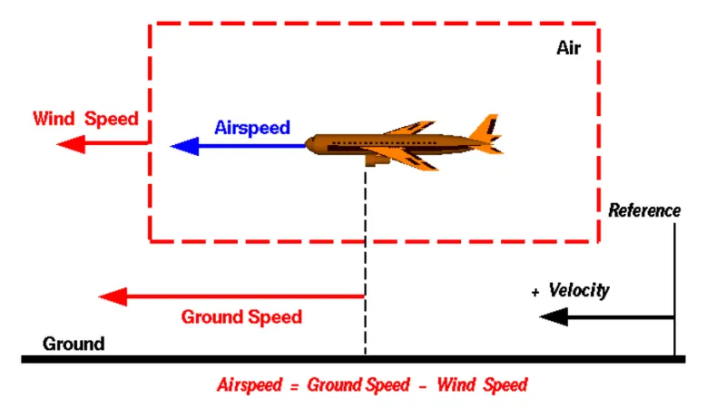
Note: The airspeed is equal to the ground speed. But if the wind is blowing in the same direction that the aircraft is moving, the airspeed will be less than the ground speed.
AIM: Why is it not recommended to use aircraft engine power to move it on the ground at Airport?
Boeing commercial airplanes are equipped with engines rated from 18,000 to nearly 100,000 lb of thrust. Such thrust levels provide for safe takeoff, flight, and landing over a wide range of temperatures, altitudes, gross weights, and payload conditions.It is not recommended to use FULL engine power to move the aircraft in the airport because of safety reasons and to prevent hazards. Aircraft operated at full thrust could create high volumes of air spreading debris or damaging other aircraft or ground vehicles.
Some of the disadvantages of using aircraft power include:
- Risk of injury to the ground staff personnel who may be in close.
- The pilot who is in the cockpit may not have the better view to taxi the aircraft when compared to the view of the pushback truck driver.
- Using aircraft engine power could also consume a considerable amount of the fuel.
- Aircrafts when using engine power are prone to much noise and can run too fast to Control.
However, when we are assuming passenger commuter aircraft and large airliners, Aircraft move using their own engine power (Limited Power) all the time on the airport apron and taxiways under their own power to go towards runways and after landing taxi to their assigned gate.The only time they use external assistance is to pushback from the gate. Large turbofan aircraft need help to reverse via a pushback tractor. The engines are turned on after the pushback is complete and the aircraft can move forward under It’s own power. To be accurate, some aircraft can reverse using a variable pitch prop or thrust reversing on turbofans but generally reversing is done via pushback tractors. Blasting jet reversers blows debris In the crowded gate area creating foreign object damage hazard for adjacent aircraft, gate equipment or terminal waiting area glass windows.
AIM: How an aircraft is pushed to runway when its ready to take off?
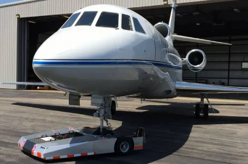
In aviation, pushback is an airport procedure during which an aircraft is pushed backwards away from its parking position, usually at an airport gate by external power. Pushbacks are carried out by special, low-profile vehicles called pushback tractors or tugs.
Although many aircraft are capable of moving themselves backwards on the ground using reverse thrust (a procedure referred to as a powerback), the resulting jet blast or prop wash would cause increased noise, damage to the terminal building or equipment, and hurt airport staff due to high-speed debris. This debris would also be sucked into the engine, as it is in normal use, and cause excessive wear - a major cause of wear on aircraft engines is during ground use. A pushback is therefore the preferred method when ground-handling aircraft.
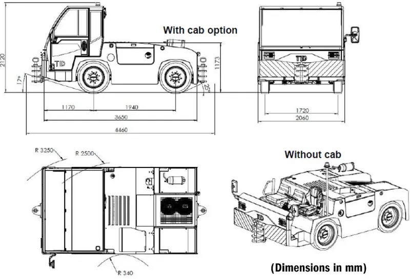
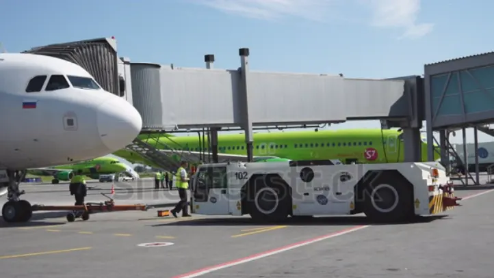
Airplanes have engines, and they can use them to move forward along the ground. So they push themselves to the runway. It true that most of the time, a small vehicle is needed to push the airplane backwards away from the terminal building, because even if a plane can reverse it’s thrust, it’s not always safe to hit the buildings with a jet blast. So the little trucks push the jets back away from the buildings, but after that, the plane can apply a small amount of engine power to roll forward.
The modern approach to this pushback is electric. It involves employing motor on the front wheels of the aircraft to move the aircraft either forward, reverse or a 180 degree tilt. This has numerous advantages over pushback trucks such as lesser taxing times, less labor, less maintanence etc. The FUTURE of PUSHBACK is ELECTRIC Without a pushback truck.
Pocedure:
- Pushbacks at busy aerodromes are usually subject to ground control clearance to facilitate ground movement on taxiways.
- Once clearance is obtained, the pilot will communicate with the tractor driver (or a ground handler walking alongside the aircraft in some cases) to start the pushback.
- To communicate, a headset may be connected near the nose gear.
- Since the pilots cannot see what is behind the aircraft, steering is done by the pushback tractor driver and not by the pilots.
- Depending on the aircraft type and airline procedure, a bypass pin may be temporarily installed into the nose gear to disconnect it from the aircraft's normal steering mechanism.
- Once the pushback is completed, the towbar is disconnected, and any bypass pin removed.
- The ground handler will show the bypass pin to the pilots to make it clear that it has been removed.
- The pushback is then complete, and the aircraft can taxi forward under its own power.
AIM: Learn about take off power, tyre design, rolling resistance, tyre pressure, brake forces when landing.
Takeoff: is the phase of flight in which an aerospace vehicle leaves the ground and becomes airborne. For aircraft traveling vertically, this is known as liftoff. On take-off, in order to position the aircraft to a safe height away from terrain and obstacles (i.e. a flight path of maximum height and minimum ground distance desired), the engine thrust is set to a high ‘take-off power’ setting (although this is not necessarily full power) and the aircraft attitude is pitched up to maintain a specific speed.
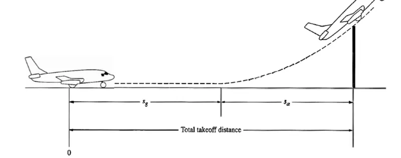
An airplane is motionless at the end of a runway. This is denoted by location O. The pilot releases the brakes and pushes the throttle to maximum takeoff power, and the airplane accelerates down the runway. At some distance from its starting point, the airplane lifts into the air. The distance the airplane cover along the runway before it lifts into the air is called the ground roll (sg). The total takeoff distance also includes the extra distance covered over the ground after the airplane is airborne but before it clears an obstacle of 50 ft for military aircraft and 35 ft for commercial aircraft. This is denoted by sa. The sum of sg and sa is the total takeoff distance.
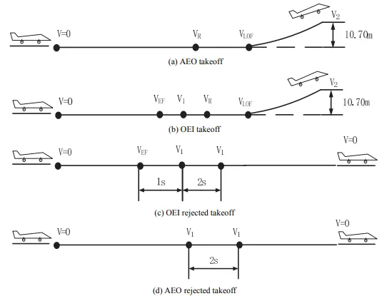
Takeoff Power: When an aircraft takes off, one or more engines may fail suddenly and it may encounter a variety of situations. There are four basic situations which should be researched for calculating the takeoff performance of an aircraft, including:
- Takeoff with all engines operating(AEO),
- Takeoff with one engine inoperative(OEI),
- Rejected takeoff with all engines operating,
- Rejected takeoff with one engine inoperative.
Figure, shows the above four takeoff situations and marks several important takeoff speeds.
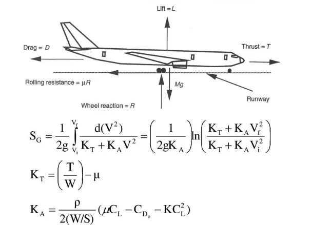
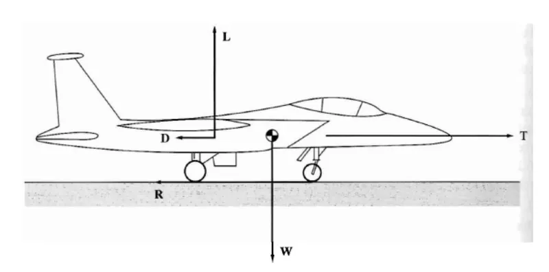
Take off performance can be predicted using a simple measure of the acceleration of the aircraft along the runway based on force equilibrium.
The forces involve: `(dV)/dt=(T−D−F)/m`
where,
- dV/dt is the acceleration along the runway and m is the mass of the vehicle.
- T – Thrust of propulsion system pushing aircraft along runway.
- D – Aerodynamic Drag of vehicle resisting the aircraft motion.
- F – Rolling resistance friction due to the contact of wheels or skids on the ground.
- During take-off run the imbalance in these forces will produce an acceleration along the runway.
- The procedure for take-off will be that the vehicle will accelerate until it reaches a safe initial flying speed. The pilot can then rotate the vehicle to an attitude to produce climb lift and it will ascend from the ground. The determination of this safe flying speed or rotation speed, VR, is a critical factor in determining take-off performance.
Take-off rules vary slightly depending on the aircraft category. Small commuter aircraft should be considered as FAR 23 rules, transport category aircraft should comply with FAR 25 rules. For safety reasons VR is usually determined as being 1.1 × VSTALL or 1.05 × VMIN CONTROL.
Use of Tyre: An aircraft tyre is designed to withstand extremely heavy loads while landing, take off, taxing, and parking. The number of wheels required for aircraft increases with the weight of the aircraft, as the weight of the aeroplane needs to be distributed more evenly.
Construction and Design of Tyre: Carcass plies are used to form the tire. They are sometimes called casing plies. An aircraft tyre is constructed for the purpose it serves.
- They support the weight of an aircraft while it is on the ground.
- It also provides the necessary traction for braking and stopping of an aeroplane.
- Tyre also helps to absorb the shock of landing and provide cushioning the roughness of takeoff, roll-out, and taxi operations.
They are design based on above Parameters:
- Retreading: Retreading is methods of restoring a worn tyre by renewing the tread area or by renewing the tread area plus one or both sidewalls. Repairs are included in the tyre retreading process
- Load Rating: Load rating is the maximum permissible load at a specified inflation pressure
- Ply Rating: Ply Rating is used to identify the maximum recommended load rating and inflation pressure for a specified tyre. It is an index of tyre strength.
- Speed Rating: The speed rating is the maximum takeoff speed to which the tyre has been tested.
- Skid Depth: Skid depth is the distance between the tread surface and the deepest groove as measured in the mould.
Unlike an automobile or truck tyre, it does not have to carry a load for a long period of continuous operation. However, an aircraft tyre absorbs the high impact loads of landing, and also it’s operating at high speeds for a short time when required.
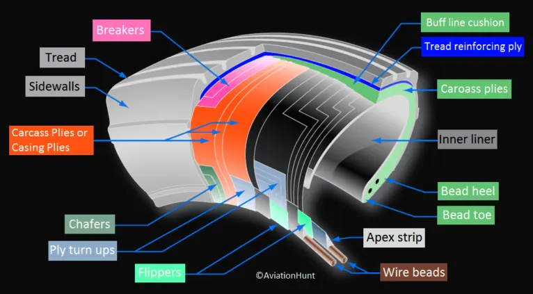
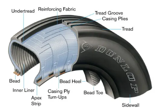
Types of Tyres Can be used:
- Tube-Type or Tubeless
- Radial or Bias
All commercial aircraft tyres approved under FAA Requirement Technical Standard Order (TSO) C62. A TSO is a minimum performance standard for specified materials, parts, and appliances used on civil aircraft.
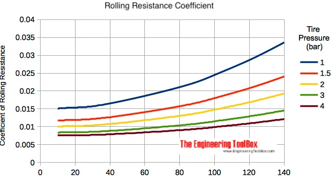
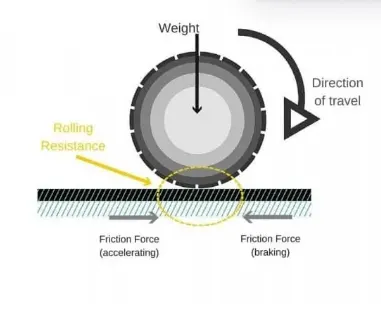
Rolling Resistance: Rolling resistance is the combination of forces that work against the forward motion of your vehicle. The weight of the vehicle, gravity and inertia, the amount of friction between the tires and the road surface, and air drag all play a part. The more rolling resistance, the more power it takes to propel a vehicle.
Rolling resistance can be expressed as: `F_(rr)=μ_(rr)⋅m⋅g`
where,
- `F_(rr` is the rolling resistance force,
- `μ_(rr` is the coefficient of rolling resistance
- `m` is the mass (in kg)
- `g` is the acceleration due to gravity
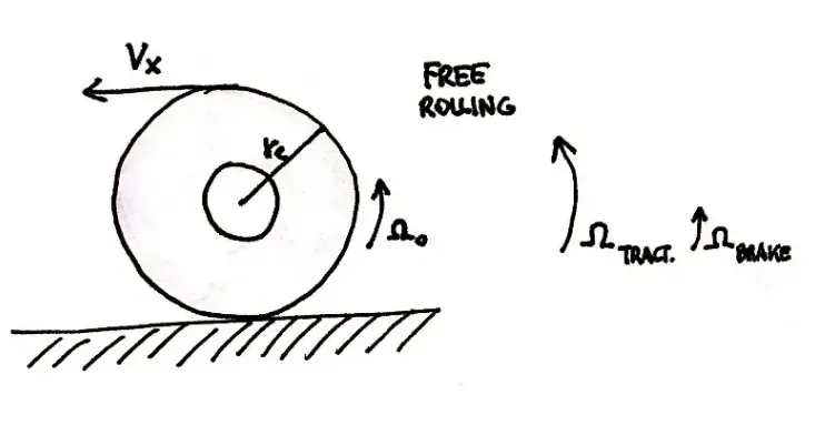
`r_e=V_x/Ω_0`
Longitudinal slip:`κ=−(V_x−r_eΩ)/V_x=−(Ω_0−Ω)/Ω_0`
where Ω denotes the angular velocity in traction or braking; the lateral slip is defined as tanα=−VyVx
The friction between aircraft and runway will be proportional to the normal force exerted by the aircraft on the runway.F=μ(W−L) The normal force will be the difference between Weight of aircraft and Lift, the friction coefficient will be typically of a magnitude of 0.02 for a standard tarmac runway.
Tyre pressure: Air pressure in tires is measured in pounds per square inch, or PSI; usually, the recommended pressure ranges between 30 and 35 PSI for Vehicles And for Planes Typically upto 200PSI.
Aircraft tires generally operate at high pressures, up to 200 psi (14 bar; 1,400 kPa) for airliners, and even higher for business jets. The main landing gear on the Concorde was typically inflated to 232 psi (16.0 bar), while its tail bumper gear tires were as high as 294 psi (20.3 bar).
Tests of airliner aircraft tires have shown that they are able to sustain pressures of maximum 800 psi (55 bar; 5,500 kPa) before bursting. During the tests the tires have to be filled with water, to prevent the test room being blown apart by the energy that would be released by a gas when the tire bursts. Aircraft tires are usually inflated with nitrogen to minimize expansion and contraction from extreme changes in ambient temperature and pressure experienced during flight.
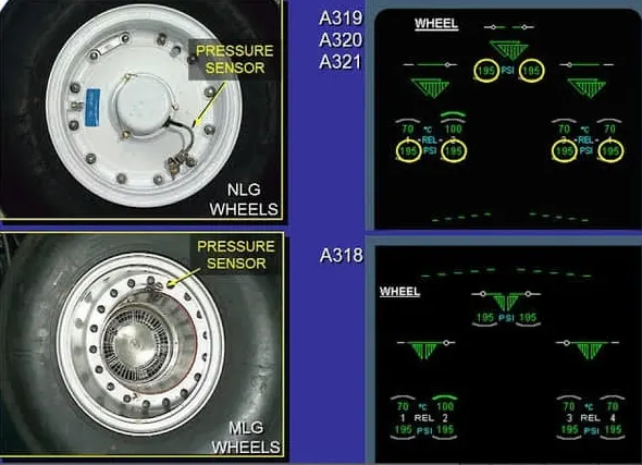
Dry nitrogen expands at the same rate as other dry atmospheric gases (normal air is about 80% nitrogen), but common compressed air sources may contain moisture, which increases the expansion rate with temperature. The requirement that an inert gas, such as nitrogen, be used instead of air for inflation of tires on certain transport category airplanes was prompted by at least three cases in which the oxygen in air-filled tires had combined with volatile gases given off by a severely overheated tire and exploded upon reaching autoignition temperature. The use of an inert gas for tire inflation eliminates the possibility of tire explosion.
Several precautions can be taken to prevent these types of accidents, including:
- Using a regulator.
- Using inflation cages.
- Following established maintenance manual procedures.
- Outfitting all servicing equipment with regulators.
- Inflating wheel/tire assemblies only with nitrogen.
Brake Forces When Landing: Airplanes rely on a braking system to safely land on runways. At cruising altitude, most commercial airplanes fly at a speed of roughly 500 to 600 mph. When landing, however, they must reduce their speed. A typical 747, for instance, has a landing speed of about 160 to 170 mph. And upon touching the runway, airplanes must quickly brake until they come to a complete stop.
Different Brakings Systems-
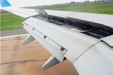
- Wing Spoilers: Many airplanes use wing spoilers to assist with braking when landing. Not to be confused with ailerons, spoilers are extendable flaps on the ends of an airplane’s wings. Pilots can raise the spoilers to decelerate the airplane as it approaches the runway. And even while on the runway, pilots will typically leave the wing spoilers raised. Raised wing spoilers create drag, which essentially slows down the airplane so that it’s able to brake more quickly.
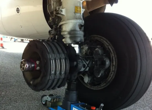
- Disk Brake: In addition to wing spoilers, airplanes use disc brakes. Airplane disc brakes are similar to the braking system in automobiles. They consist of a pair of calipers that, when engaged, squeeze pads against the rotors of an airplane’s landing gear. Disc brakes are designed to remain static at all times. In other words, they don’t rotate with the wheels of an airplane’s landing gear.
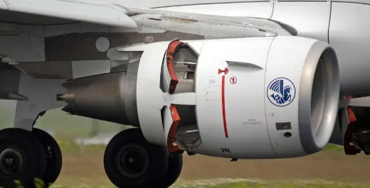
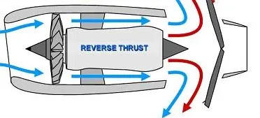
- Reverse Thrust: many jet airplanes use reverse thrust to assist with braking during landings. Reverse thrust is a feature in jet engine airplanes that, as the name suggests, involves the reversal of the engines’ thrust. When flying, the thrust is projected out the rear of an airplane’s engines. When landing, however, pilots may use the reverse thrust feature. Reverse thrust changes the direction of the engines’ thrust. Rather than projecting out the rear, the thrust will be projected out the front. This reversal of thrust provides deceleration that allows airplanes to slow down more quickly when landing.
AIM: With necessary assumptions, calculate the force and power required to push / pull an aircraft by a towing vehicle.
Assumptions:
- Let's consider Weight of Airbus A380 = 79 tonnes = 79,000 Kg.
- Consider the towing vehicle to be Mototok Spacer 8600, Weight of the Mototok Space 8600 = 5400 Kg.
- let `μ_(rr)`=0.002
- Drag coefficient (Cd)= 0.025
- Air Density ρ = 1.125 kg/m^3.
- Frontal Area (A): 150 m^2
- Velocity (V)= 5.4 kmph or 1.5 m/s
Let us analyse various forces to be overcome to push the aircraft:
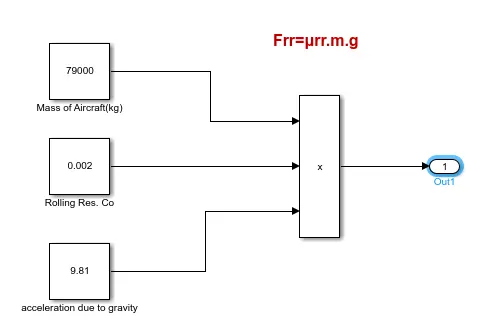
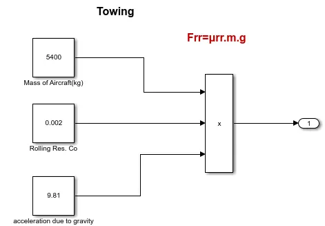
Rolling resistance force(`F_(rr`): Rolling resistance is the force resisting the motion when a body rolls on a surface. It is the friction force that is needed to beovercome to move a vehicle. The kinetic energy of the wheels is partially converted into heat. The rolling resistance is proportional to the normalforce perpendicular to the rolling wheel and is approximated by the rolling resistance coefficient urr. Therefore, Equation that can be used for the rollingresistance force of the entire system is-
`F_(rr)=μ_(rr).m.g`
Where,
- `mu_(rr)` is Rolling Resistance Coeficient.
- `m` Mass of Aircraft.
- `g` is the acceleration due to gravity.
`F_(rr)= 0.002*79000*9.81= 1550 N` For Aircraft.
`F_(rr)= 0.002*5400*9.81= 105.9 N` For Towing Vehicle
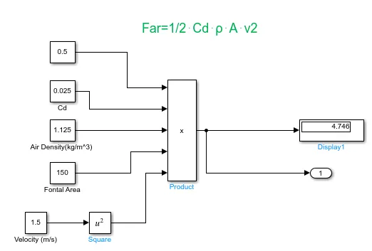
Aerodynamic resistance force`F_(ar)`: Aerodynamic drag force is the force which is required to keep a vehicle moving. There are two component of this force , one isshape drag (due to the shape of the vehicle) and another is skin friction (due to friction between air and skin of the vehicle). When the vehicle moves the velocityof air near boundary is higher than the air surrounding. Both the tug and the aircraft will experience some aerodynamic drag. For completeness, the aerodynamicdrag force caused by the aircraft and towing vehicle can be given by Equation below-
`F_(ar)=1/2⋅C_d⋅ρ⋅A⋅v^2`
Where,
- V is Velocity of Aircraft.
- `C_d` Drag coefficient.
- ρ is Air Density.
- A is Frontal Area.
`F_(ar)=1/2⋅0.025⋅1.125⋅150⋅1.5^2`
Therefore, Airdrag force `F_(ar` is 4.746 N
Note: Generally Towing vehicles are designed such that their frontal area is very less. Hence the air drag force due to them is very small and can be neglected.
Hill climb resistance(`F_(hc`): Hill climbing force is the force needed to move the vehicle in up gradient. To Hill Climbing force the expression of the equation isgiven below-
`F_(hc)=m*g*sin(φ)`
where,
- m = Total mass of the vehicle(vehicle mass + payload) in kg.
- g = Gravitational constant that is 9.8 m/s^2
- φ = up gradient angle or inclination angle in radian
The taxiways on the airport are constructed flat. In this case up gradient angle(φ) = 0, Hence gradient or hill climb force is neglected.
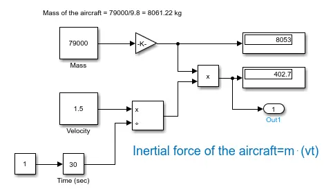
Inertia force of the aircraft: Mass of the aircraft = `79000/9.8= 8061.22` kg.
Inertial force of the aircraft=`m⋅(v/t)`
where,
- t is the towing time, which is for 30 sec(Let).
- m is mass.
- v is velocity is m/s.
Inertial force of the aircraft is `8061.22*(1.5/30)= 403 N`
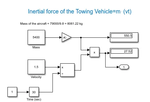
Inertial force of the Towing Vehicle:
Mass of the towing vehicle= `5400/9.8= 551 kg`
Inertial force = `551* (1.5/30)= 27.55 N`
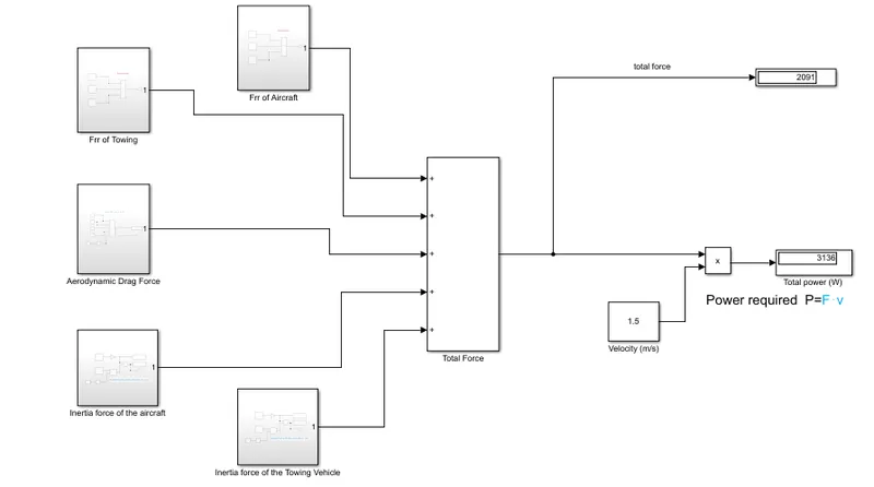
Therefore, Total force requirement = Rolling Resistance force(Aircraft + Towing Vehicle) +Aerodynamic Drag Force +Total Ineria Force(Towing Vehicle + Aircraft)
`(1550+105.9)+4.74+(403+27.55)= 2.091` KN(approx).
Power required `P=F⋅v`
`P=2091⋅1.5`
`3136 W = 3.136`kw
Therefore, the power required to push / pull an Airbus A320 at 5.4 km/hr by the Mototok Spacer 8600 towing vehicle is 3.136 kW.
AIM: Develop the model for the calculated force and power using Simulink.
Simulink Model: For Calculating All forces related and power required by Towing Vehicle/Tractor.
Rolling Resistance Calculation Model: For both Aircraft and Towing vehicles Tyres.
Aerodynamic Drag Force Calculation Model: Towing avehicles are having very small frontal area so, aerodynamic drag forces are very small. Therefore, Neglected.
Inertia Forces Calculation Model: Inertia Forces are causes by both Vehicle and Aircraft due to their weight.
AIM: Design an electric powertrain with type of motor, it’s power rating, and energy requirement to fulfill aircraft towing application in Simulink. Estimate the duty cycle range to control the aircraft speed from zero to highest. Make all required assumptions. Prepare a table of assumed parameters. Draw a block diagram of powertrain.
Assumption For Powertrain Design:
- Aircraft Mass(kg) 575,000 kg
- Towing Vehicle mass(kg) 50,000 kg
- Rolling Resistance Co-efficient 0.013
- Air Density1.225 kg/m3
- Towing Vehicle Drag Co-efficient 0.5
- Aircraft Drag Co-efficient0.09
- Frontal area 20 m^2
- Inclination angle 0 rad
- Tyre Pressure 203 PSI /14 bar
- Towing Velocity(V) 10 km/h = 2.778 m/s
- Towing Time(t) 2 min = 120sec
- Radius of thetowing vehicle wheel 0.15 m
Block Diagram of powertrein Towing Vehicle: The block diagram shows the basic topology of an electric power train. The Design of the each and every component of the power train based on our need.
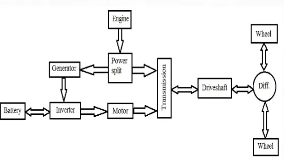
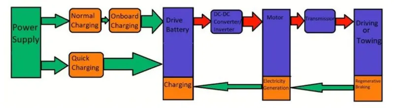
Selection Of Motor & Design: From Above Question We have seen that Power required is 3136W (i.e. 3.136KW) So, We must choose motor power power rating at least to full fill this Load Capacity, Now Lets Try to Analysis Torque required: `T=(F⋅r)/(G⋅η_g)`
Where,
- G is the gear ratio of the transmission system, & Let G = 27.
- `η_g` is the gear efficiencyFor Mototok's towing vehicles & Let efficiency is 95%.
- Radius of the wheels (r) = 0.15 m
So, Torque `T= (2091* 0.15)/(27* 0.95)= 12.228`Nm
Now, Lets Find Angular Speed for Towing: `w = P_(out)/T_(out)`
`w=3136/12.228` = 255.3745 rad/sec (Approx 2444RPM)
So, the Motor Required-
- 3.1KW
- 12.5Nm
- 2450 RPM
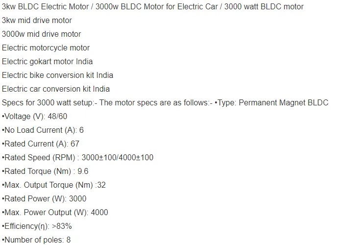
Battery Selection/Design: As the rated torque of the motor is almost equal to the required torque, let us assume that the full load current is supplied by the battery to the motor. `I_i=P_i/(√3⋅V_i⋅cosϕ`
Input Power = Output Power / Efficiency
Input Power = 3136/0.83 = 3778W
`I_i= 3778/(1.732*45*1)= 48~33 A`
From the data sheet, voltage `V_i`=60V Therefore, current supplied by the battery is 33~48 A.That implies Battery voltage `V_(bat)=P_i/I_i`
`3778/60`= 62~83 Volts, Therefore battery voltage must be 85 Volts(approx).
Energy requirement of the battery `E=P_i⋅t`
where, t is the total time time of discharge of battery. Assuming total time of discharge as 120 seconds.
E= 3778*120= 453360 J = 453.3KJ
E= 453360/(3600)= 126 Wh
Chopper/Controller Design: In a DC chopper `V_o= D. V_(i n)`
where,
- D is the duty cycle.
- `V_(i n` is input voltage.
Here, Maximum Output Voltage(Vo) allowed is the voltage rating of the motor. Vo cannot exceed 65V as it is the rated voltage of the motor. Vin= 83V
`D_(max)= 60/83`= 0.722 Therefore, the duty cycle can range from 0 to 0.7228 to control the speed of the towing vehicle from zero to highest.
Here, I have selected BLDC Motor based on calculated parameter and futher calculaion done by accordingly. But Designer can take Induction Motor also Based on above parameters and all calculation can be done accordingly, only change will be in above calculation is Power Factor came into consideration.
Design the parameters in excel sheet:
In Sheet given, Voltage rating taken is Minimum and that's why Duty cycle is also minimum. if we consider Max voltages then duty cycle will also be Max(like in Above Question).

In Excel Sheet Desiger can add any kind of motor Charateristics and can find the required Battey parameter, and Chopper parameters.
- Time taken here in sec, which is active time of Towing vehicle
- This time will help to calculate Required battery energy.
- Duty Cycle is calculated Out/inp.
- Battery voltage is rated voltage required by motor.