Project-1: Powertrain for aircraft in runways
1. Search and list out the total weight of various types of aircrafts.
Here below I have attached the list of the total weight of various types of aircrafts.
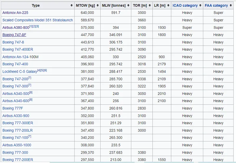
- The aircraft gross weight (also known as the all-up weight and abbreviated AUW) is the total aircraft weight at any moment during the flight or ground operation.
- An aircraft's gross weight will decrease during a flight due to fuel and oil consumption. An aircraft's gross weight may also vary during a flight due to payload dropping or in flight refuelling.
- At the moment of releasing its brakes, the gross weight of an aircraft is equal to its takeoff weight. During flight, an aircraft's gross weight is referred to as the en-route weight or in-flight weight.
- An aircraft's gross weight is limited by several weight restrictions in order to avoid overloading its structure or to avoid unacceptable performance or handling qualities while in operation.
- Aircraft gross weight limits are established during an aircraft's design and certification period and are laid down in the aircraft's type certificate and manufacturer specification documents.
- The absolute maximum weight capabilities of a given aircraft are referred to as the structural weight limits. The structural weight limits are based on aircraft maximum structural capability and define the envelope for the CG charts (both maximum weight and CG limits).
- An aircraft's structural weight capability is typically a function of when the aircraft was manufactured, and in some cases, old aircraft can have their structural weight capability increased by structural modifications.
- There various types of weight included in aircrafts here we can see brifly of each types.
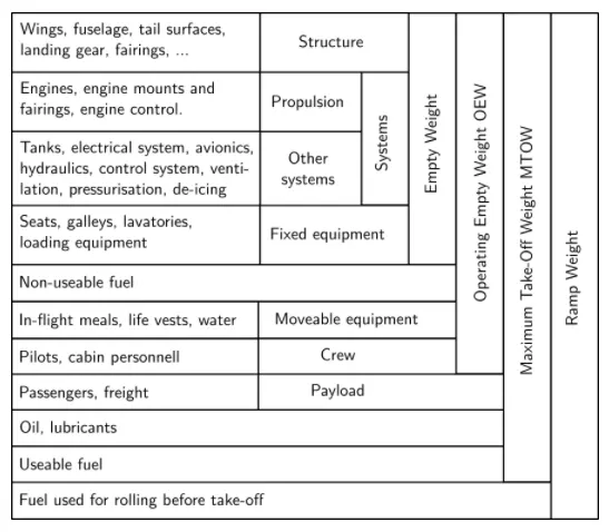
There two types of weight limitations.
I. Design weight limits:
- An aircraft's gross weight is limited by several weight restrictions in order to avoid overloading its structure or to avoid unacceptable performance or handling qualities while in operation.
- Aircraft gross weight limits are established during an aircraft's design and certification period and are laid down in the aircraft's type certificate and manufacturer specification documents.
1. Manufacturer's Weight Empty (MWE)
- It is also called as Licensed Empty Weight.
- It is the weight of the aircraft "as built" and includes the weight of the structure, power plant, furnishings, installations, systems and other equipment that are considered an integral part of an aircraft.
- This excludes any baggage, passengers, and usable fuel.
2. Maximum design taxi weight (MDTW)
- The maximum design taxi weight (also known as the maximum design ramp weight (MDRW)) is the maximum weight certificated for aircraft manoeuvring on the ground (taxiing or towing) as limited by aircraft strength and airworthiness requirements.
3. Maximum design takeoff weight (MDTOW)
- Is the maximum certificated design weight when the brakes are released for takeoff and is the greatest weight for which compliance with the relevant structural and engineering requirements has been demonstrated by the manufacturer.
4. Maximum design landing weight (MDLW)
- The maximum certificated design weight at which the aircraft meets the appropriate landing certification requirements. It generally depends on the landing gear strength or the landing impact loads on certain parts of the wing structure.
- The MDLW must not exceed the MDTOW.
- The maximum landing weight is typically designed for 10 feet per second (600 feet per minute) sink rate at touch down with no structural damage.
5. Maximum design zero-fuel weight (MDZFW)
- The maximum certificated design weight of the aircraft less all usable fuel and other specified usable agents (engine injection fluid, and other consumable propulsion agents).
- It is the maximum weight permitted before usable fuel and other specified usable fluids are loaded in specified sections of the airplane. The MDZFW is limited by strength and airworthiness requirements.
- At this weight, the subsequent addition of fuel will not result in the aircraft design strength being exceeded.
- The weight difference between the MDTOW and the MDZFW may be utilised only for the addition of fuel.
6. Minimum flight weight (MFW)
- Minimum certificated weight for flight as limited by aircraft strength and airworthiness requirements.
II. Authorised weight limits
- Aircraft authorised gross weight limits (also referred to as certified weight limits) are laid down in the aircraft flight manual(AFM) and/or associated certificate of airworthiness (C of A). The authorised or permitted limits may be equal to or lower than the Design weight limits.
- The authorised weight limits that can legally be used by an operator or airline are those listed in the AFM and the weight and balance manual.
- The authorised (or certified) weight limits are chosen by the customer/airline and they are referred to as the "purchased weights". An operator may purchase a certified weight below the maximum design weights because many of the airport operating fees are based on the aircraft AFM maximum allowable weight values. An aircraft purchase price is, typically, a function of the certified weight purchased.
- Maximum weights established, for each aircraft, by design and certification must not be exceeded during aircraft operation (ramp or taxying, takeoff, en-route flight, approach, and landing) and during aircraft loading (zero fuel conditions, centre of gravity position, and weight distribution).
- Weights could be restricted on some type of aircraft depending on the aircraft handling requirements; for example aerobatic aircraft, where certain aerobatic manoeuvres can only be executed with a limited grossweight.
- In addition, the authorised maximum weight limits may be less as limited by centre of gravity, fuel density, and fuel loading limits.
Maximum taxi weight (MTW)
- The maximum taxi weight (MTW) is the maximum weight authorized for maneuvering (taxiing or towing) an aircraft on the ground as limited by aircraft strength and airworthiness requirements. It includes the weight of taxi and run-up fuel for the engines and the APU.
- It is greater than the maximum takeoff weight due to the fuel that will be burned during the taxi and runup operations.
- The difference between the maximum taxi/ramp weight and the maximum take-off weight (maximum taxi fuel allowance) depends on the size of the aircraft, the number of engines, APU operation, and engines/APU fuel consumption, and is typically assumed for 10 to 15 minutes allowance of taxi and run-up operations.
Maximum takeoff weight (MTOW)
- The maximum takeoff weight (also known as the maximum brake-release weight) is the maximum weight authorised at brake release for takeoff, or at the start of the takeoff roll.
- The maximum takeoff weight is always less than the maximum taxi/ramp weight to allow for fuel burned during taxi by the engines and the APU.
- In operation, the maximum weight for takeoff may be limited to values less than the maximum takeoff weight due to aircraft performance, environmental conditions, airfield characteristics (takeoff field length, altitude), maximum tire speed and brake energy, obstacle clearances, and/or en route and landing weight requirements.
Maximum landing weight (MLW)
- The maximum weight authorised for normal landing of an aircraft.
- The MLW must not exceed the MTOW.
Maximum zero-fuel weight (MZFW)
- The maximum permissible weight of the aircraft less all usable fuel and other specified usable agents (engine injection fluid, and other consumable propulsion agents). It is the maximum weight permitted before usable fuel and other specified usable fluids are loaded in specified sections of the airplane.
2. Is there any difference between ground speed and air speed?
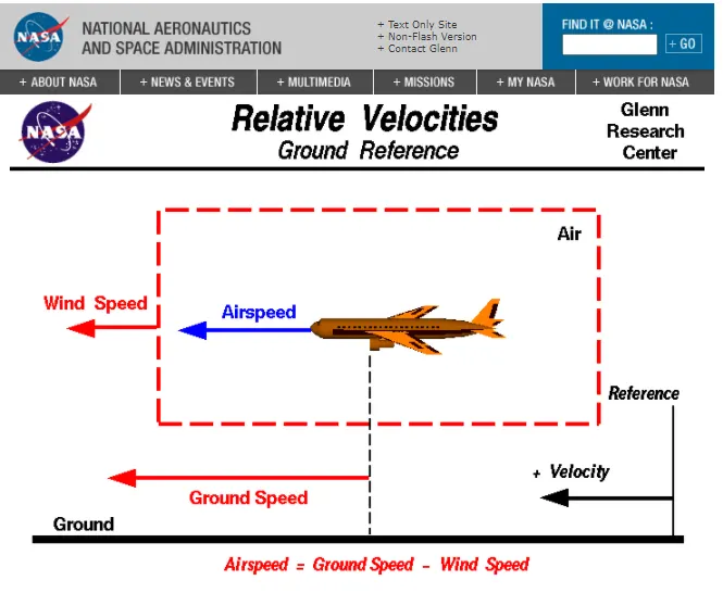
Air speed :
- It is the speed of the aircraft relative to the airflow around the aircraft
- Airspeed is also the speed with which air is flowing around the aircraft
- body. It affects the aircraft speed in all directions
- Airspeed determines if there is enough flow of air around aircraft body to provide the lift force.
- Airspeed is the difference between the aircraft speed and wind speed
- During tailwind, airspeed is comparatively lower
- During headwind, airspeed is higher
Ground speed:
- It is the speed of an aircraft relative to the surface of earth.
- Ground speed is the horizontal speed of an aircraft and it is zero if the aircraft moves vertically.
- Ground speed determines the time taken to reach the destination.
- Groundspeed is the sum of aircraft speed and wind speed.
- During tailwind, Ground speed is aided by wind speed and it is comparatively higher
- Headwind offers resistance to aircraft and slows down the groundspeed.
3. Reasons for not using airplane engine to move on the ground:
- Ground has more obstruction due to which the airplane requires precise maneuring.
- The pilot in the cockpit does not have good view of the ground obstructions. Hence towing truck is assists the plane to maneure properly.
- Airplane engine has very low eficiency at low power setting required for taxiing or moving on the ground. Taxiing is the movement of plane to reach runway or hangar and this operation requires hundreads of liters of fuel. In order to save fuel, engine power is not required.
- Engine can be used in powerback mode, wherein engine runs to provide reverse thrust. But the airplane is required to move backwards at the terminal gate. So the reverse thrust can damage the terminal building or push the debris and dirt in front of the engine which could get sucked into engine when it powers forward damaging the engine.
- Airplane engines make harsh noise which disturbs the surrounding.
- The thrust obtained at the rear end of the engine is so powerful that could cause serious damage to the objects on the backside of the plane.
- There is high chance of accident due to the thrust on ground. For the safety concerns, airplane is towed.
4. How an aircraft is pushed to runway:
- The process of moving the airplane to runway when it is ready to take-off is called as Taxiing.
- During Taxiing the plane runs on its own power on its wheels. The wheels on the front-side of plane are called nose wheels
- and the wheels on rear-side are called tail wheels.
- The steering maneuer is achieved by turning either the nose wheels or tail wheels. The thrust to move forward is gained by propellers or jet engines.
- During taxiing, plane moves slow on taxiway at speed of 30-35 km/h
5. Learn about take off power, tyre design, rolling resistance, tyre pressure, brake forces when landing.
Take-Off Power
- Take-off is the phase of flight in which an aerospace vehicle leaves the ground and becomes airborne.
- For aircraft that take off horizontally, this usually involves starting with a transition from moving along the ground on a runway.
- For light aircraft, usually full power is used during take-off. Large transport category aircraft may use a reduced power for take-off, where less than full power is applied in order to prolong engine life, reduce maintenance costs and reduce noise emissions.
- The aircraft is permitted to accelerate to rotation speed. The term rotation is used because the aircraft pivots around the axis of its main landing gear while still on the ground, usually because of gentle manipulation of the flight controls to make or facilitate this change in aircraft attitude and once proper air displacement occurs under or over the wings, an aircraft will lift off on its own.
- The ground roll is the distance from brake release to the initiation of the rotation, when the pilot pulls the control wheel (or stick or yoke) backward in order to raise the nose of the aircraft. This maneuver is required to increase the area of attack of the airplane to help it become airborne.
- The aircraft typically remains in this attitude for some 1-3 seconds, depending on aircraft size, before the tires lose contact with the ground. This segment is called the rotation. The rotation phase concludes as the aircraft lifts off the ground and begins the transition and subsequent climb phase.
Why are tyres important in Aircraft?
- When it comes to safety tyres are one of the most important components of aircraft. They help to absorb the shock of landing and provide cushioning. It also provides the necessary traction for braking and stopping of an aircraft.
- An aircraft tyre is designed to withstand extremely heavy loads while landing, take off, taxing, and parking. The number of wheels required for aircraft increases with the weight of the aircraft, as the weight of the aeroplane needs to be distributed more evenly.
Design and Construction of Aircraft tyre
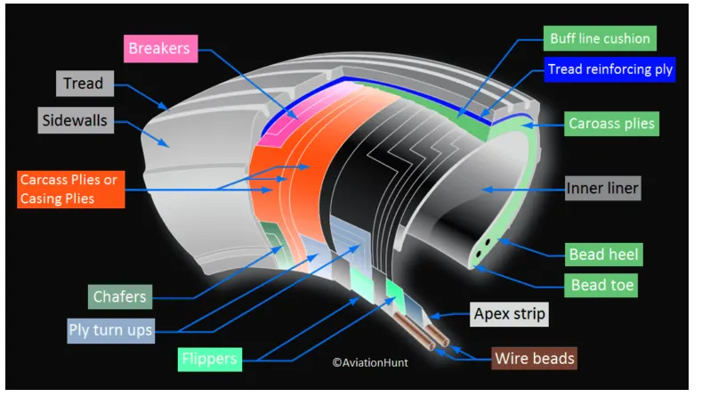
- Carcass plies are used to form the tire. They are sometimes called casing plies. An aircraft tyre is constructed for the purpose it serves.
- They support the weight of an aircraft while it is on the ground.
- It also provides the necessary traction for braking and stopping of an aeroplane.
- Tyre also helps to absorb the shock of landing and provide cushioning the roughness of takeoff, roll-out, and taxi operations.
- Unlike an automobile or truck tyre, it does not have to carry a load for a long period of continuous operation. However, an aircraft tyre absorbs the high impact loads of landing, and also it’s operating at high speeds for a short time when required.
Let’s go through some technical aspects of the tyre:
- Retreading – Retreading is methods of restoring a worn tyre by renewing the tread area or by renewing the tread area plus one or both sidewalls. Repairs are included in the tyre retreading process.
- Load Rating – Load rating is the maximum permissible load at a specified inflation pressure.
- Ply Rating – Ply Rating is used to identify the maximum recommended load rating and inflation pressure for a specified tyre. It is an index of tyre strength.
- Speed Rating – The speed rating is the maximum takeoff speed to which the tyre has been tested.
- Skid Depth – Skid depth is the distance between the tread surface and the deepest groove as measured in the mould.
Aircraft tyres must have an approved speed and load rating and have sufficient clearance when retracted through landing gear to allow for tyre growth. Tyre growth is the increase in the size of the tyre due to centrifugal forces at high speed.
Aircraft tyres may be Tube-type or Tubeless
Tubeless tyres are more advantageous over tube-type. There is no longer the use of tube-type tyre in recent aviation. Nowadays all airliners are using tubeless tyres. Tubeless that are meant to be used without a tube has the word TUBELESS on the sidewall of the tyre.
Aircraft tyres may be Radial or Bias
Almost all airliners are using Radial tyre. Bias is an older design, and it’s mainly used for road vehicles. Radial tyres have the word RADIAL on the sidewall. Radial tires are more expensive than bias-ply tyres. Radial tires are in demand because of their lower life cycle cost and long term value.
Aircraft tyres are cconductive:
- Today’s tyres are conductive. Aircraft tyres are manufactured with tread rubber with conducting compounds to permit earthing of static charges.
- In early days when tyres were not sufficiently conductive, aircraft used to have a conductive strip hanging down from the axle of the landing gear. Upon landing, this strip would be the first part of the aircraft to touch the earth. This discharges any static electricity accumulated on the outer surfaces of the aircraft. Now you don’t see them anymore.
What is the purpose of Chines in aviation tyre
- Chines are also called deflectors. Chine tyre used on the nose wheel of aircraft, specially fuselage-mounted jet engines. It diverts runway water away from the engine inlets.
- Chines are circumferential protrusions that are moulded into the sidewall of nose tyres that deflect water sideways to help reduce excess water ingestion into the engines. Tyres may have chines on one or both sides, depending on the number of nose tyres on the aircraft.
Aircraft Tyre Standards
- Each tyre manufacturer produces their own designs of the tyre with different tread patterns, wear patterns, wear limits etc, and in some cases, different names for the same part of the tyre. But all tyres must meet the approved standards before being accepted by the FAA or CAA.
- All commercial aircraft tyres approved under FAA Requirement Technical Standard Order (TSO) C62. A TSO is a minimum performance standard for specified materials, parts, and appliances used on civil aircraft.
Tyre pressure:
- The tyre is inflated according to the aircraft manufacturer's maintenance manual.
- The tyre is not inflated directly according to the sidewall information or how the tyre appears.
- The tyre pressure in unloaded condition and loaded condition can vary as much as 4% .
- Under-inflated tyre can flex beyond the design limits of tyre. This can weaken the carcass construction and cause internal damage that is invisible externally.
- Tyre pressure changes ccording to the ambient temperature. For every 5 degree Fahrenheit change in the temperature, the tyre pressure changes by 1%. If the airplane is flying to colder ambient temperature, then the tyre might be in
- under-inflated condition. This problem is overcome by over-inflating tyres at hotter ambient temperature departure regions. But this infltion is made sure to be in design limits.
- The aircraft tyre pressure is checked 3 hours after landing so that it cools to ambient temperature. The manufacturer of tyre provides table of appropriate pressure at different ambient temperature.
- Under-inflation of tyre causes uneven wear of tread and premature replacement of tyre. It causes the sidewall to be pinched between wheel rim and runway. It causes the slip of beads on the rim.
- Over-inflation causes tread wear at the center of tyre periphery and the tyre is not completely in touch with ground.
- Under-inflation causes tread wear at shoulders of tyre.
Rolling resistance:
Rolling resistance is the force opposing the motion of airplane on the ground when the tyres are in touch with the runway. This force depends on the rolling resistance co-efficient, weight of aircraft and the lift forces acting on the aircraft. The rolling resistance is not constant, because as the velocity changes during take-off roll and landing rollout, the lift force varies accordingly which impacts the normal force acting at the tyre-road interface.
Braking power:
- During the landing roll-out or rejected take-off, the airplane is required to decelerate and stop in a smooth way. Three airplane components can be used in coordination to generate required braking force. Those components are engine, brakes and mechanical spoilers. Braking force required to stop airplane is directly proportional to its weight.
- Engine: The engine thrust lever is put to idle position to reduce the forward moving thrust to zero.
- Due to inertia, the plane still keeps moving in the same direction. This can be overcome by putting the engine in reverse thrust or reverse propeller pitch mode. Reverse thrust is used only at high speeds when the brakes cannot generate sufficient force.
- Once the airplane groundspeed reduces sufficiently, thrust lever should be put to idle position so that engine don't consume foreign object debris.
Part B:
6. A. With necessary assumptions, calculate the force and power required to push / pull an aircraft by a towing vehicle.
Fromula Requered for this calculations:
1. Rolling Resistance force (Frr)=μrr*m*g (Newton)
Where, μrr- rolling resistance co-efficient
m- mass of the vehicle, here m=(Kerb Weight (kg)+ Payload (kg))
g- gravitation force due to gravity
The coefficient of rolling resistance is a function of the tire material, tire structure, tire temperature,tire inflation pressure,tread geomentry(design),road roughness,road material.
The value of coefficient of rolling resistance is inversly proposional to tire pressure. If tire pressure increases means the value of coefficient of rolling resistance is decreases, If the tire pressure decreases means the value of coefficent of rolling resistance is increases.
2. Aerodynamic drag force (Fad)=1/2*ρACdV^2 (Newton)
Where ρ= air density Kg/m^3, A- Frontal area m^2, Cd- Drag coefficent, V- velocity
The drag coefficent Cd is depends upon shape of the vehicle.
3. Total power of the vehicle at the given speed in kw (P)=[(Frr+Fad)*Vehicle speed(V)]KW
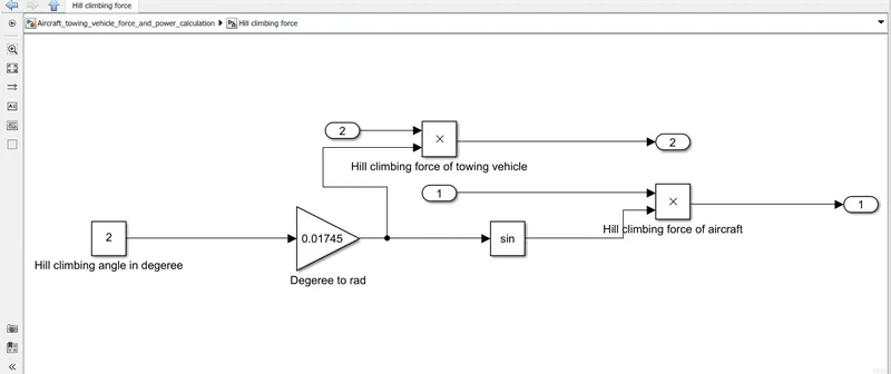
4. Hill climbing force Fh=m*g*sinΦ (Newton)
Where m- mass of the vehicle
g- gravitation force due to gravity
Φ- angle of slop or hill in radian
Hill climbing power (P)= [Fh* speed of the vehicle (V)] KW
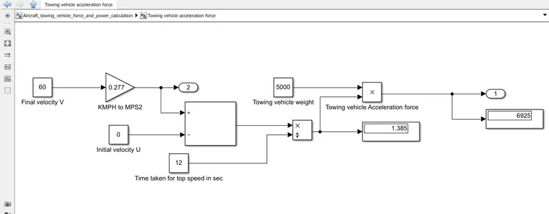
5. Acceleration (0 to top speed in specified seconds) A= [Final velocity(V) - Initial velocity(U) /Acceleration time requred to attain the top speed(T)] m/sec^2.
A=(V-U)/T
I. Acceleration force= M*A (Newton)
Where M= mass of the vehicle, here m=(Kerb Weight (kg)+ Payload (kg))
A=Acceleration of the vehicle form 0 to top speed in specified time
II. Acceleration power=[Acceleration force* top speed of the vehicle]
Aircraft Assumptions:
- Mass of the aircraft: m = 75,000 Kg
- Rolling resistane coefficient μ = 0.03
- Acceleration due to gravity: g = 9.81ms^2
- Frontal area of an aircraft: A = 100m^2
- Speed of aircraft=50Kmph
- Final speed of an aircraft: v = 0
- Initial speed of an aircraft: u = 0
- Coefficient of drag of an aircraft: Cd = 0.015
- Density of air: ρ = 1.25kgm^3
- Acceleration time of aircraft: t = 0
Tow vehicle assumptions:
- Mass of the tow vehicle: m = 5,000 Kg
- Rolling resistane coefficientμ = 0.4
- Acceleration due to gravity: g = 9.81ms^2
- Frontal area of tow vehicle: A = 3.2m/s
- Speed of tow vehicle=50Kmph
- Final speed of tow vehicle: v = 60kmph
- Initial speed of tow vehicle: u = 0
- Coefficient of drag of tow vehicle Cd = 0.5
- Density of air: ρ = 1.25kgm^3
- Acceleration time of tow vehicle: t = 12s
Here below i have attached the power calculation Excel sheet for your reference.
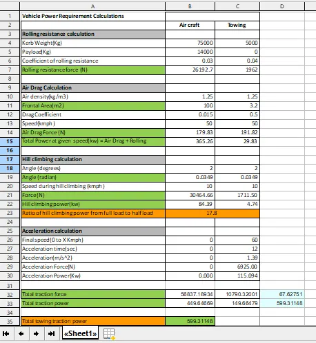
As per calculation, Total Towing Power required is 599.3Kw
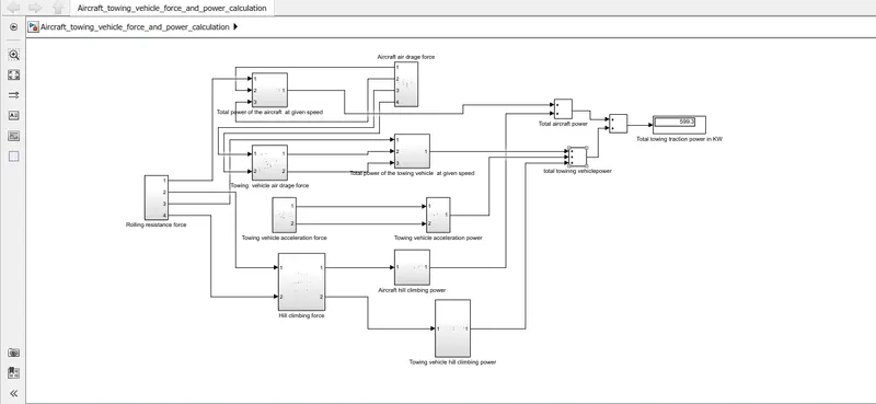
B. Develop the model for the calculated force and power using Simulink.
Here below i have attached the simulink model for calculate force and power of tow vehicle.
Rolling resistance subsystem:

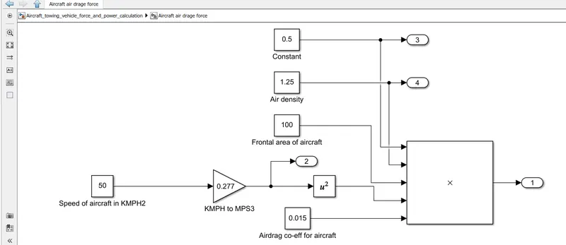
Airdrag force subsystem:
Hill climbing force subsystem:
Acceleration force subsystem:
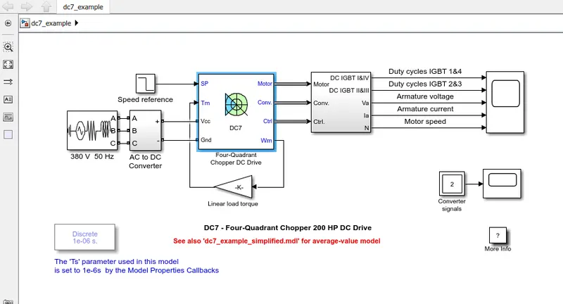
7. A. Design an electric powertrain with type of motor, it’s power rating, and energy requirement to fulfill aircraft towing application in Simulink. Estimate the duty cycle range to control the aircraft speed from zero to highest. Make all required assumptions. Prepare a table of assumed parameters. Draw a block diagram of powertrain.
(Hint :DC7 Block)
Assumed parameters of aircraft towing vehicle:
- Mass of the tow vehicle: m = 5,000 Kg
- Rolling resistane coefficientμ = 0.4
- Acceleration due to gravity: g = 9.81ms^2
- Frontal area of tow vehicle: A = 3.2m/s
- Speed of tow vehicle=50Kmph
- Final speed of tow vehicle: v = 60kmph
- Initial speed of tow vehicle: u = 0
- Coefficient of drag of tow vehicle Cd = 0.5
- Density of air: ρ = 1.25kgm^3
- Acceleration time of tow vehicle: t = 12s
- Gradeability 2 %
Assumed parameters of aircraft:
- Mass of the aircraft: m = 75,000 Kg
- Rolling resistane coefficient μ = 0.03
- Acceleration due to gravity: g = 9.81ms^2
- Frontal area of an aircraft: A = 100m^2
- Speed of aircraft=50Kmph
- Final speed of an aircraft: v = 0
- Initial speed of an aircraft: u = 0
- Coefficient of drag of an aircraft: Cd = 0.015
- Density of air: ρ = 1.25kgm^3
- Acceleration time of aircraft: t = 0
Total traction force required 67.62KN
Total power required 599.31 kW
Assum wheel radius of towing vehicle as 0.5m
Torque required at the wheels= (Total Traction force required)*(wheel radius of towing vehicle)
Tw=(67.62*0.5*1000)= 33810Nm
Selection of motor:
- From the above assumed parameters i have calculated total torque and power required.
- This aircraft towing vehicle is low speed and high torque application.
- So the motor that best suits for this towing vehicle is choosen by study the diffrent charactristics of different motors.
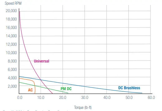
- from the above graph for the different motor types individually, it is difficult to accurately compare each motor’s performance against the others.
- The Motor Types Graph maps the speed-torque curves of all four motor types on one graph, using the same scale to clearly illustrate the differences between the motors.
- This comparison shows the dramatically higher no-load speed of a universal and the significantly higher starting torques of PMDC and BLDC motors.
- So for this towing vehicle application we have choosen the Permanent magnet DC motor.
- This motor is capable at providing very high torque at very low speeds.
Here below i have attached the block diagram of powertrain.
Duty cycle:
- Duty cycle is an important parameter for the power electronics switch between the battery and motor.
- The motor is required to be supplied with gradually changed voltage values but if the batter is directly connected to the motor, motor receives full battery voltage and runs at rated speed instantaneously.
- So in order to regulate the voltage in gradual manner power electronics switches
- come into picture.
- Duty cycle is the ratio of amount of time the switches are required to be ON to the total time period (sum of ON and OFF period).
- Duty cycle can be calculated with the ratio of power supplied to the motor (or output power of power electronics circuit) to the power supplied by the battery (or input power to the power electronics circuit).
- Required output power of the motor for towing application at highest speed of 60 km/h
Assume parameters to calculate duty cycle:
Motor requried outpur power from calculation is Pout=599.31 kW
Motor efficiency=87%
We know that Motor efficiency=(Pout/Pin) from this we can calculate the motor requried input power.
Pin=(599.31KW/87)=688.86KW
Therefore the output required from power electronic circuit to feed to motor is 688.86KW.
Assume source voltage and current parameters:
Source voltage Vs=400V
Source current Is=1800A
We know that Power=(Voltage*Current) Watts
Source power=(400*1754)
Therefore source power= 720KW
We already know that duty cycle D= Pout/Pin
D=688.86/720= 0.956
Therefore the duty cycle range required to control the aircraft towing vehicle speed from zero to highest is 95.6%