Project-1: Powertrain for aircraft in runways
Aim:
Part A:
- Search and list out the total weight of various types of aircrafts.
- Is there any difference between ground speed and air speed?
- Why is it not recommended to use aircraft engine power to move it on the ground at Airport?
- How an aircraft is pushed to runway when its ready to take off?
- Learn about take off power, tyre design, rolling resistance, tyre pressure, brake forces when landing.
Part B:
- A. With necessary assumptions, calculate the force and power required to push / pull an aircraft by a towing vehicle.
- Develop the model for the calculated force and power using Simulink.
- A. Design an electric powertrain with type of motor, it’s power rating, and energy requirement to fulfill aircraft towing application in Simulink. Estimate the duty cycle range to control the aircraft speed from zero to highest. Make all required assumptions. Prepare a table of assumed parameters. Draw a block diagram of powertrain.
(Hint :DC7 Block)
B. Also, Design the parameters in excel sheet.
- Search and list out the total weight of various types of aircrafts.
When looking at different aircraft's specifications or in POHs/AFMs, there are several different weights of the aircraft mentioned (e.g. maximum take-off weight, maximum landing weight, operating empty weight).
The different terms represent different weights or masses. For each flight, the weights are taken into account for several reasons.
Manufacturer's empty weight (MEW)
Also called Manufacturer's Weight Empty (MWE) or Licensed Empty Weight . It is the weight of the aircraft "as built" and includes the weight of the structure, power plant, furnishings, installations, systems and other equipment that are considered an integral part of an aircraft. This excludes any baggage, passengers, or usable fuel2.
Zero-fuel weight (ZFW)
This is the total weight of the airplane and all its contents (including unusable fuel), but excluding the total weight of the usable fuel on board. As a flight progresses and fuel is consumed, the total weight of the airplane reduces, but the ZFW remains constant.
Maximum zero fuel weight (MZFW) is the maximum weight allowed before usable fuel and other specified usable agents (engine injection fluid, and other consumable propulsion agents) are loaded.
Operating empty weight (OEW) (Roughly equivalent to basic empty weight on light aircraft)
It is the basic weight of an aircraft including the crew, all fluids necessary for operation such as engine oil, engine coolant, water, unusable fuel and all operator items and equipment required for flight but excluding usable fuel and the payload.
Payload
It is the carrying capacity of an aircraft. It includes cargo, people, extra fuel. In the case of a commercial airliner, it may refer only to revenue-generating cargo or paying passengers.
Maximum takeoff weight (MTOW)
This is the maximum weight at which the pilot of the aircraft is allowed to attempt to take off3.
Regulated takeoff weight (RTOW)
Depending on different factors (e.g. flap setting, altitude, air temperature, length of runway), RTOW or maximum permissible takeoff weight varies for each takeoff. It can never be higher than MTOW. More information is on this answer.
Maximum landing weight (MLW)
This maximum weight at which an aircraft is permitted to land3.
The following image depicts takeoff weight components.
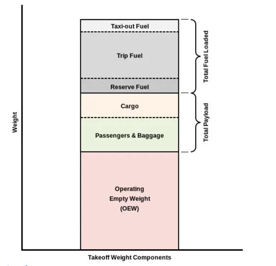
Maximum ramp weight (MRW)
Also called maximum taxi weight (MTW). It is the maximum weight authorized for maneuvering (taxiing or towing) an aircraft on the ground.
Aircraft gross weight
It is the total aircraft weight at any moment during the flight or ground operation. This decreases during flight due to fuel and oil consumption.
There are a number of ways to identify aircraft by type. The primary distinction is between those that are lighter than air and those that are heavier than air.
Lighter-than-air
Aircraft such as balloons, nonrigid airships (blimps), and dirigibles are designed to contain within their structure a sufficient volume that, when filled with a gas lighter than air (heated air, hydrogen, or helium), displaces the surrounding ambient air and floats, just as a cork does on the water. Balloons are not steerable and drift with the wind. Nonrigid airships, which have enjoyed a rebirth of use and interest, do not have a rigid structure but have a defined aerodynamic shape, which contains cells filled with the lifting agent. They have a source of propulsion and can be controlled in all three axes of flight. Dirigibles are no longer in use, but they were lighter-than-air craft with a rigid internal structure, which was usually very large, and they were capable of relatively high speeds.
Heavier-than-air
This type of aircraft must have a power source to provide the thrust necessary to obtain lift. Simple heavier-than-air craft include kites. These are usually a flat-surfaced structure, often with a stabilizing “tail,” attached by a bridle to a string that is held in place on the ground. Lift is provided by the reaction of the string-restrained surface to the wind.
MTOW = Maximum take-off weight, MLW = Maximum landing weight, TOR = Take-off run , LR = Landing run
|
Type |
MTOW [kg] |
MLW [tonnes] |
TOR [m] |
LR [m] |
||
|
640,000 |
591.7 |
3500 |
Heavy |
Super |
||
|
589,670 |
3660 |
Heavy |
Super |
|||
|
575,000 |
394 |
3100 |
1930 |
Super |
Super |
|
|
447,700 |
346.091 |
3100 |
1800 |
Heavy |
Heavy |
|
|
443,613 |
306.175 |
3100 |
Heavy |
Heavy |
||
|
412,770 |
295.742 |
3090 |
Heavy |
Heavy |
||
|
Antonov An-124-100M |
405,060 |
330 |
2520 |
900 |
Heavy |
Heavy |
|
396,900 |
295.742 |
3018 |
2179 |
Heavy |
Heavy |
|
|
381,000 |
288.417 |
2530 |
1494 |
Heavy |
Heavy |
|
|
377,840 |
285.700 |
3338 |
2109 |
Heavy |
Heavy |
|
|
377,840 |
260.320 |
3222 |
1905 |
Heavy |
Heavy |
|
|
371,950 |
240 |
3050 |
2010 |
Heavy |
Heavy |
|
|
367,400 |
256 |
3100 |
2100 |
Heavy |
Heavy |
|
|
347,800 |
260.816 |
2830 |
Heavy |
Heavy |
||
|
352,000 |
251.5 |
3100 |
Heavy |
Heavy |
||
|
351,800 |
251.29 |
3100 |
Heavy |
Heavy |
||
|
347,450 |
223.168 |
3000 |
Heavy |
Heavy |
||
|
340,200 |
265.300 |
Heavy |
Heavy |
|||
|
308,000 |
233.5 |
Heavy |
Heavy |
|||
|
299,370 |
237.683 |
3380 |
Heavy |
Heavy |
||
|
297,550 |
213.00 |
3380 |
1550 |
Heavy |
Heavy |
|
|
276,700 |
190 |
3000 |
1926 |
Heavy |
Heavy |
|
|
273,300 |
185 |
2990 |
1890 |
Heavy |
Heavy |
|
|
270,000 |
175 |
2670 |
1860 |
Heavy |
Heavy |
|
|
270,000 |
195.04 |
3115 |
2118 |
Heavy |
Heavy |
|
|
256,280 |
183 |
2990 |
1890 |
Heavy |
Heavy |
|
|
254,000 |
192.777 |
2900 |
Heavy |
Heavy |
||
|
254,000 |
201.849 |
Heavy |
Heavy |
|||
|
253,500 |
181 |
2990 |
Heavy |
Heavy |
||
|
250,000 |
175 |
2600 |
1980 |
Heavy |
Heavy |
|
|
242,000 |
185 |
2500 |
1750 |
Heavy |
Heavy |
|
|
242,000 |
180 |
2220 |
1750 |
Heavy |
Heavy |
|
|
231,300 |
166.92 |
2636 |
Heavy |
Heavy |
||
|
228,000 |
172.365 |
3300 |
1695 |
Heavy |
Heavy |
|
|
211,400 |
Heavy |
Heavy |
||||
|
208,000 |
175 |
Heavy |
Heavy |
|||
|
204,000 |
158.758 |
3414 |
Heavy |
Heavy |
||
|
192,000 |
140 |
2385 |
1555 |
Heavy |
Heavy |
|
|
187,000 |
136.08 |
2713 |
1676 |
Heavy |
Heavy |
|
|
185,000 |
111.1 |
3440 |
2220 |
Heavy |
Heavy |
|
|
163,000 |
138 |
2324 |
1536 |
Heavy |
Heavy |
|
|
159,000 |
136.078 |
2713 |
1676 |
Heavy |
Heavy |
|
|
157,000 |
124 |
2290 |
1490 |
Heavy |
Heavy |
|
|
152,000 |
151.9 |
Heavy |
Heavy |
|||
|
151,000 |
97.5 |
Heavy |
Heavy |
|||
|
151,000 |
112.1 |
Heavy |
Heavy |
|||
|
147,000 |
Heavy |
Heavy |
||||
|
142,000 |
123 |
1860 |
1480 |
Heavy |
Heavy |
|
|
141,000 |
122 |
980 |
770 |
Heavy |
Heavy |
|
|
140,000 |
Heavy |
Heavy |
||||
|
125,000 |
Medium |
Large |
||||
|
124,000 |
101.6 |
2550 |
1750 |
Medium |
Large |
|
|
117,000 |
86.3 |
Medium |
Large |
|||
|
116,000 |
89.9 |
2347 |
1555 |
Medium |
Large |
|
|
106,000 |
79.5 |
Medium |
Large |
|||
|
104,000 |
79.5 |
Medium |
Large |
|||
|
104,000 |
80 |
Medium |
Large |
|||
|
104,000 |
87.5 |
2250 |
Medium |
Large |
||
|
87,500 |
Medium |
Large |
||||
|
85,000 |
66.36 |
2500 |
1704 |
Medium |
Large |
|
|
85,000 |
71.35 |
2804 |
1829 |
Medium |
Large |
|
|
84,000 |
70.1 |
Medium |
Large |
|||
|
Airbus A321-100[18] |
83,000 |
77.8 |
2200 |
1540 |
Medium |
Large |
|
79,000 |
65.32 |
2308 |
1634 |
Medium |
Large |
|
|
78,000 |
68.1 |
Medium |
Large |
|||
|
73,000 |
63.28 |
Medium |
Large |
|||
|
72,500 |
62.4 |
Medium |
Large |
|||
|
72,500 |
62.4 |
Medium |
Large |
|||
|
71,000 |
64.41 |
2165 |
1520 |
Medium |
Large |
|
|
70,700 |
Medium |
Large |
||||
|
70,000 |
58.06 |
1921 |
1415 |
Medium |
Large |
|
|
Airbus A320-100[18] |
68,000 |
66 |
1955 |
1490 |
Medium |
Large |
|
68,000 |
54.9 |
2540 |
1540 |
Medium |
Large |
|
|
68,000 |
Medium |
Large |
||||
|
67,000 |
Medium |
Large |
||||
|
66,000 |
54.66 |
1796 |
1340 |
Medium |
Large |
|
|
65,000 |
57.61 |
1890 |
1494 |
Medium |
Large |
|
|
65,000 |
Medium |
Large |
||||
|
64,000 |
62.5 |
1850 |
1470 |
Medium |
Large |
|
|
63,000 |
51.7 |
1939 |
1396 |
Medium |
Large |
|
|
60,000 |
49.9 |
1832 |
1360 |
Medium |
Large |
|
|
59,000 |
50.80 |
1463 |
1356 |
Medium |
Large |
|
|
59,000 |
57.5 |
1375 |
1340 |
Medium |
Large |
|
|
55,000 |
47.174 |
1950 |
Medium |
Large |
||
|
55,000 |
Medium |
Large |
||||
|
54,000 |
Medium |
Large |
||||
|
50,000 |
46.265 |
1950 |
Medium |
Large |
||
|
50,000 |
Medium |
Large |
||||
|
48,600 |
Medium |
Large |
||||
|
48,500 |
Medium |
Large |
||||
|
48,000 |
43 |
2056 |
1323 |
Medium |
Large |
|
|
46,000 |
Medium |
Large |
||||
|
46,000 |
39.95 |
1621 |
1350 |
Medium |
Large |
|
|
44,000 |
Medium |
Large |
||||
|
42,000 |
36.74 |
Medium |
Large |
|||
|
39,000 |
Medium |
Large |
||||
|
37,500 |
32.8 |
2244 |
1304 |
Medium |
Large |
|
|
36,500 |
33.345 |
1778 |
1596 |
Medium |
Large |
|
|
36,000 |
32.8 |
1644 |
1274 |
Medium |
Large |
|
|
33,000 |
30.39 |
1564 |
1478 |
Medium |
Large |
|
|
33,000 |
Medium |
Large |
||||
|
30,400 |
Medium |
Large |
||||
|
28,000 |
28.01 |
1219 |
1295 |
Medium |
Large |
|
|
23,000 |
21.319 |
1918 |
1479 |
Medium |
Large |
|
|
22,800 |
22.35 |
1333 |
914 |
Medium |
Large |
|
|
22,800 |
21.5 |
1300 |
Medium |
Large |
||
|
22,000 |
19.3 |
2270 |
1380 |
Medium |
Large |
|
|
18,600 |
18.3 |
1165 |
1126 |
Medium |
Small |
|
|
13,150 |
12.930 |
1300 |
1030 |
Medium |
Small |
|
|
11,500 |
11.25 |
1560 |
1380 |
Medium |
Small |
|
|
10,890 |
10.570 |
1493 |
826 |
Medium |
Small |
|
|
9,752 |
8.709 |
1353 |
811 |
Medium |
Small |
|
|
8,300 |
7.665 |
893 |
724 |
Medium |
Small |
|
|
8,150 |
7.65 |
956 |
677 |
Medium |
Small |
|
|
7,765 |
7.605 |
1036 |
853 |
Medium |
Small |
|
|
7,761 |
7.103 |
1039 |
896 |
Medium |
Small |
|
|
7,000 |
Medium |
Small |
||||
|
4,800 |
4.43 |
975 |
741 |
Light |
Small |
Ref - https://en.wikipedia.org/wiki/List_of_airliners_by_maximum_takeoff_weight
2) Is there any difference between ground speed and air speed?
There are two different types of speed when talking about airplanes – ground speed and airspeed.
While ground speed is the airplane’s speed relative to the surface of the Earth, airspeed – at least true airspeed – is its speed relative to the air it is flying in.
Below, I will explain the two types of speed in more detail, as well as talk about the four types of airspeed that are commonly used.
Airspeed vs Ground Speed
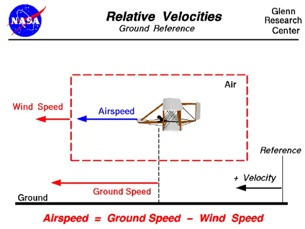
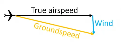
As mentioned above, true airspeed is simply the speed at which an aircraft is moving relative to the air it is flying in. As such, it’s also the speed at which the air is flowing around the aircraft’s wings.
Ground speed, on the other hand, is the aircraft’s speed relative to the ground. One thing that should be noted here is that it’s its horizontal rather than vertical speed – an aircraft climbing completely vertically would have a ground speed of zero.
In other words, while airspeed is what determines whether there is enough airflow around an aircraft to make it fly, ground speed is what determines how fast an aircraft will get to its destination.
Wind’s Effect on Ground Speed
The relationship between airspeed and ground speed is fairly simple. Ground speed is simply the sum of airspeed and wind speed.
If the aircraft is flying in the same direction as the wind is blowing, the aircraft experiences tailwind, and its ground speed is higher than its airspeed. On the other hand, if the wind is blowing against the direction the aircraft is traveling in, the aircraft experiences headwind, and its ground speed is lower than its airspeed.
For pilots, both airspeed and ground speed are very important. While the first of those helps them make sure they are flying fast enough to take off, not to stall, and so on, the second one helps them figure out how long it will take them to get from one place to another.
3) Why is it not recommended to use aircraft engine power to move it on the ground at Airport?
Airplanes move on the ground the same way they move through the air: Using the thrust generated by their turbine engines. The wheels turn freely and merely support the weight of the plane.
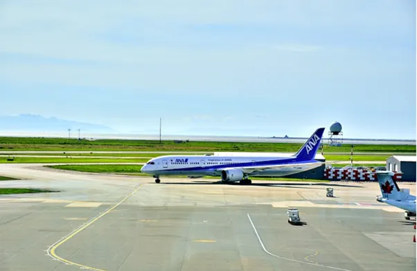

Taxiing is an important process for nearly all airplanes. From small and medium-sized airliners to large wide-body airliners, most airplanes require taxiing while on the runway. Before taking off and after landing, for example, airplanes must taxied. What is airplane taxiing exactly, and how does it work?
Taxiing refers to the movement of an airplane while on the runway. As these airplanes transport passengers to their intended destination, they must land at an airport. Airports, of course, only have a limited amount of runway space. Therefore, airplanes must be taxied off the runway after landing so that they won’t block or otherwise prevent other airplanes from using the same airport.
Taxiing is simply the process of moving an airplane while it’s on the runway. It occurs after an airplane has landed, and it occurs before an airplane takes off. Airplanes don’t actually fly while on the ground. As a result, the process by which they move on the runway isn’t known as flying; it’s known as taxiing.
So How Taxiing Works ?
There are different ways that airplanes can be taxied. Taxiing is most commonly performed using an airplane’s own propulsion system. For propulsion, most airplanes have either jet engines or propellers. Engaging the propulsion system allows airplanes to move while on the runway.
Some airplanes also have thrust reversers. Thrust reversers live up to their namesake by changing the direction of an airplane’s thrust. In jet-engine airplanes, thrust reversers can assist with taxiing. It essentially allows airplanes to back up while on the runway.
Pilots must still steer airplanes when taxiing them on. Steering is performed using the same control systems as flying an airplane. Pilots can turn the nose wheel or rudder to change the direction in which their airplanes travel while on the runway.
Taxiing vs Towing
It’s important to note that taxiing isn’t the same as towing. When many people hear the word “taxiing,” they envision a ground vehicle physically moving an airplane on the runway. Taxiing, though, specifically involves the use of an airplane’s own propulsion system to move while on the runway. Towing, on the other hand, refers to the use of a ground vehicle. Known as a tug, these ground vehicles connect to airplanes so that they can move and turn airplanes.
4) How an aircraft is pushed to runway when its ready to take off?
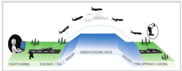
Taxiing refers to the movement of an aircraft on the ground, under its own power. The aircraft moves on wheels. An airplane uses taxiways to taxi from one place on an airport to another; for example, when moving from a terminal to the runway.
The aircrafts always move on the ground following the yellow lines, to avoid any collision with the surrounding buildings, vehicles or other aircrafts. The taxiing motion has a speed limit. Before making a turn, the pilot reduces the speed further to prevent tire skids. Just like cars, there is a certain list of priorities during taxiing. The aircrafts that are landing or taking off have higher priority. The other aircrafts have to wait for these aircrafts before they start or continue taxiing.
The thrust to propel the aircraft forward comes from its propellers or jet engines. Steering is achieved by turning a nose wheel or tail wheel/rudder; the pilot controlling the direction travelled with their feet. The use of engine thrust near terminals is restricted due to the possibility of jet blast damage. This is why the aircrafts are pushed back from the buildings by a vehicle before they can start their own engines for taxiing.
Take-Off
Take-off is the phase of flight in which an aircraft goes through a transition from moving along the ground (taxiing) to flying in the air, usually starting on a runway. Usually the engines are run at full power during take-off. Following the taxi motion, the aircraft stops at the starting line of the runway. Before takeoff, the engines, particularly piston engines, are routinely run up at high power to check for engine-related problems. This makes a considerable noise. When the pilot releases the brakes, the aircraft starts accelerating rapidly until the necessary speed for take-off is achieved.
The takeoff speed required varies with air den- sity, aircraft weight, and aircraft configuration (flap and/or slat position, as applicable). Air density is affected by factors such as field ele- vation and air temperature.
Operations with transport category aircraft employ the concept of the takeoff V-Speeds, V1 and V2. These speeds are determined not only by the above factors affecting takeoff perform- ance, but also by the length and slope of the runway. Below V1, in case of critical failures, the takeoff should be aborted; above V1 the pilot continues the takeoff and returns for land- ing. After the co-pilot calls V1, Then, V2 (the safe takeoff speed) is called. This speed must be maintained after an engine failure to meet per- formance targets for rate of climb and angle of climb.
The speeds needed for takeoff are relative to the motion of the air (indicated airspeed). A head wind will reduce the ground speed needed for takeoff, as there is a greater flow of air over the wings. This is why the aircrafts always take off against the wind. Side wind is not preferred as it would disturb the stability of the aircraft. Typical takeoff air speeds for jetliners are in the 130–155 knot range (150–180 mph, 240–285 km/h). For a given aircraft, the takeoff speed is usually directly proportional to the aircraft weight; the heavier the weight, the greater the speed needed. Some aircraft have difficulty generating enough lift at the low speeds encountered during takeoff. These are therefore fitted with high-lift devices, often including slats and usually flaps, which increase the camber of the wing, making it more effective at low speed, thus creating more lift. These have to be deployed from the wing before performing any maneuver.
At the beginning of the climb phase, the wheels are retracted into the aircraft and the undercarriage doors are closed. This operation is audible by the passengers as a noise coming from below the floor.
Climb
Following take-off, the aircraft has to climb to a certain altitude (typically 30,000 ft or 10 km) before it can cruise at this altitude in a safe and economic way. A climb is carried out by increasing the lift of wings supporting the aircraft until their lifting force exceeds the weight of the aircraft. Once this occurs, the aircraft will climb to a higher altitude until the lifting force and weight are again in balance. The increase in lift may be accomplished by increasing the angle of attack of the wings, by increasing the thrust of the engines to increase speed (thereby increasing lift), by increasing the surface area or shape of the wing to produce greater lift, or by some combination of these techniques. In most cases, engine thrust and angle of attack are simultaneously increased to produce a climb.
Because lift diminishes with decreasing air density, a climb, once initiated, will end by itself when the diminishing lift with increasing altitude drops to a point that equals the weight of the aircraft. At that point, the aircraft will return to level flight at a constant altitude. During climb phase, it is normal that the engine noise diminishes. This is because the engines are operated at a lower power level after the take-off. It is also possible to hear a whirring noise or a change in the tone of the noise during climb. This is the sound of the flaps that are retracting. A wing with retracted flap produces less noise.
Cruise
Cruise is the level portion of aircraft travel where flight is most fuel efficient. It occurs between ascent and descent phases and is usually the majority of a journey. Technically, cruising consists of heading (direction of flight) changes only at a constant airspeed and altitude. It ends as the aircraft approaches the destination where the descent phase of flight commences in preparation for landing.
For most commercial passenger aircraft, the cruise phase of flight consumes the majority of fuel. As this lightens the aircraft considerably, higher altitudes are more efficient for additional fuel economy. However, for operational and air traffic control reasons it is necessary to stay at the cleared flight level. Typical cruising speed for long-distance commercial passenger flights is 475-500 knots (878-926 km/h; 547-578 mph).
Commercial or passenger aircraft are usually designed for optimum performance at their cruise speed. There is also an optimum cruise altitude for a particular aircraft type and conditions including payload weight, center of gravity, air temperature, humidity, and speed. This altitude is usually where the drag is minimum and the lift is maximum. As in any phase of the flight, the aircraft in cruise mode is always in communication with an Air Traffic Control (ATC) station. Although the general tendency is to follow a straight line towards the destination, there may be some deviations from the flight plan for weather, turbulence or air traffic rea- sons, after receiving clearance from ATC.
Descent
A descent during air travel is any portion where an aircraft decreases altitude. Descents are an essential component of an approach to landing. Other partial descents might be to avoid traffic, poor flight conditions (turbulence or bad weather), clouds (particularly under visual flight rules), to see something lower, to enter warmer air (in the case of extreme cold), or to take advantage of wind direction of a different altitude. Normal descents take place at a con- stant airspeed and constant angle of descent (3 degree final approach at most airports). The pilot controls the angle of descent by varying engine power and pitch angle (lowering the nose) to keep the airspeed constant.
At the beginning of and during the descent phase, the engine noise diminishes further as the engines are operated at low power settings. However, towards the end of the descent phase, the passenger can feel further accelerations and an increase in the noise. This is to realize the “final approach” before taking “landing posi- tion”.
Landing
Landing is the last part of a flight, where the aircraft returns to the ground. Aircraft usually land at an airport on a firm runway, generally constructed of asphalt concrete, concrete, gravel or grass. To land, the airspeed and the rate of descent are reduced to where the object descends at a slow enough rate to allow for a gentle touch down. Landing is accomplished by slowing down and descending to the runway. This speed reduction is accomplished by reducing thrust and/or inducing a greater amount of drag using flaps, landing gear or speed brakes. As the plane approaches the ground, the pilot will execute a flare (roundout) to induce a gentle landing. Although the pilots are trained to perform the landing operation, there are “Instrument Landing Systems” in most of the airports to help pilots land the aircrafts. An instrument landing system (ILS) is a ground-based instrument approach system that provides precision guid- ance to an aircraft approaching and landing on a runway, using a combination of radio signals and, in many cases, high-intensity lighting arrays to enable a safe landing during instrument meteorological conditions (IMC), such as low ceilings or reduced visibility due to fog, rain, or blowing snow.
At the beginning of the landing phase, the pas- sengers will hear the opening of the doors of the landing gears. As the landing gears are deployed, they will create an additional drag and an additional noise. Immediately after touch-down, the passengers can hear a blowing sound, sometimes with increasing engine sound. This is the engine’s thrust reverses, helping the aircraft to slow down to taxi speeds by redirecting the airflow of the engines for- ward. Once the aircraft is decelerated to low speed, it can taxi to the terminal building.
5) Learn about take-off power, tyre design, rolling resistance, tyre pressure, brake forces when landing.
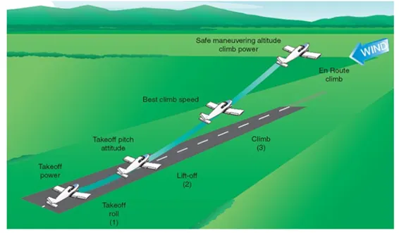
The amount of power that an engine is allowed to produce for a limited period of time for takeoff. The use of takeoff power is usually limited to 5 min for reciprocating engines and up to 2½ min for gas turbine engines. This may not always be the case. Specifically, with respect to reciprocating engines, it is the brake horsepower developed under standard, sea-level conditions and under the maximum conditions of the crankshaft rotational speed and the engine manifold pressure approved for the normal take-off. It is limited in continuous use to the period of time shown in the approved engine specifications. With respect to gas turbine engines, it is the thrust developed under static conditions at a specified altitude and atmospheric conditions of the rotor shaft rotational speed and gas temperature approved for the normal takeoff. It is limited in continuous use to the period of time shown in the approved engine specifications.
A normal takeoff is one in which the airplane is headed into the wind, or the wind is very light. Also, the takeoff surface is firm and of sufficient length to permit the airplane to gradually accelerate to normal lift-off and climb-out speed, and there are no obstructions along the takeoff path.
There are two reasons for making a takeoff as nearly into the wind as possible:
Aircraft speed will be less, therefore reducing wear and stress on landing gear
Shorter ground roll and therefore much less runway length
Take Off Roll
After taxiing onto the runway, the airplane should be carefully aligned with the intended takeoff direction, and the nose wheel positioned straight, or centered. After releasing the brakes, the throttle should be advanced smoothly and continuously to takeoff power. An abrupt application of power may cause the airplane to yaw sharply to the left because of the torque effects of the engine and propeller. This will be most apparent in high horsepower engines. As the airplane starts to roll forward, the pilot should assure both feet are on the rudder pedals so that the toes or balls of the feet are on the rudder portions, not on the brake portions. Engine instruments should be monitored during the takeoff roll for any malfunctions.
Initial Climb
Upon lift-off, the airplane should be flying at approximately the pitch attitude that will allow it to accelerate to VY. This is the speed at which the airplane will gain the most altitude in the shortest period of time.
Tyre Design
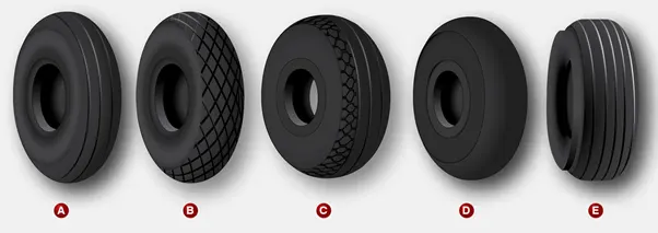
When it comes to safety, tyres are one of the most important components of aircraft. They help to absorb the shock of landing and provide cushioning. It also provides the necessary traction for braking and stopping of an aircraft.
An aircraft tyre is designed to withstand extremely heavy loads while landing, take off, taxing, and parking. The number of wheels required for aircraft increases with the weight of the aircraft, as the weight of the aeroplane needs to be distributed more evenly.
Design and Construction of Aircraft tyre
Carcass plies are used to form the tire. They are sometimes called casing plies. An aircraft tyre is constructed for the purpose it serves.
They support the weight of an aircraft while it is on the ground.
It also provides the necessary traction for braking and stopping of an aeroplane.
Tyre also helps to absorb the shock of landing and provide cushioning the roughness of takeoff, roll-out, and taxi operations.
Unlike an automobile or truck tyre, it does not have to carry a load for a long period of continuous operation. However, an aircraft tyre absorbs the high impact loads of landing, and also it’s operating at high speeds for a short time when required.
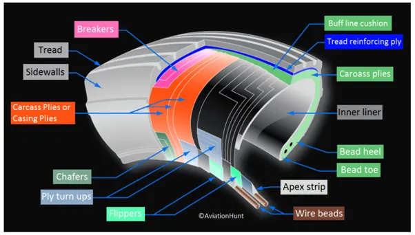
Let’s go through some technical aspects of the tyre.
Retreading – Retreading is methods of restoring a worn tyre by renewing the tread area or by renewing the tread area plus one or both sidewalls. Repairs are included in the tyre retreading process.
Load Rating – Load rating is the maximum permissible load at a specified inflation pressure.
Ply Rating – Ply Rating is used to identify the maximum recommended load rating and inflation pressure for a specified tyre. It is an index of tyre strength.
Speed Rating – The speed rating is the maximum takeoff speed to which the tyre has been tested.
Skid Depth – Skid depth is the distance between the tread surface and the deepest groove as measured in the mould.
Aircraft tyres must have an approved speed and load rating and have sufficient clearance when retracted through landing gear to allow for tyre growth. Tyre growth is the increase in the size of the tyre due to centrifugal forces at high speed.
Aircraft tyres may be Tube-type or Tubeless
Tubeless tyres are more advantageous over tube-type. There is no longer the use of tube-type tyre in recent aviation. Nowadays all airliners are using tubeless tyres. Tubeless that are meant to be used without a tube has the word TUBELESS on the sidewall of the tyre.
Aircraft tyres may be Radial or Bias
Almost all airliners are using Radial tyre. Bias is an older design, and it’s mainly used for road vehicles. Radial tyres have the word RADIAL on the sidewall. Radial tires are more expensive than bias-ply tyres. Radial tires are in demand because of their lower life cycle cost and long term value.
Today’s tyres are conductive. Aircraft tyres are manufactured with tread rubber with conducting compounds to permit earthing of static charges.
In early days when tyres were not sufficiently conductive, aircraft used to have a conductive strip hanging down from the axle of the landing gear. Upon landing, this strip would be the first part of the aircraft to touch the earth. This discharges any static electricity accumulated on the outer surfaces of the aircraft.
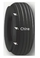
Chines are also called deflectors. Chine tyre used on the nose wheel of aircraft, specially fuselage-mounted jet engines. It diverts runway water away from the engine inlets.
Chines are circumferential protrusions that are moulded into the sidewall of nose tyres that deflect water sideways to help reduce excess water ingestion into the engines. Tyres may have chines on one or both sides, depending on the number of nose tyres on the aircraft.
Aircraft Tyre Standards
Each tyre manufacturer produces their own designs of the tyre with different tread patterns, wear patterns, wear limits etc, and in some cases, different names for the same part of the tyre. But all tyres must meet the approved standards before being accepted by the FAA or CAA.
All commercial aircraft tyres approved under FAA Requirement Technical Standard Order (TSO) C62. A TSO is a minimum performance standard for specified materials, parts, and appliances used on civil aircraft.
Rolling Resistance
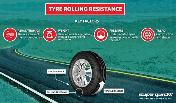
Also known as rolling friction or rolling drag, rolling resistance is the energy required to keep your vehicle’s tyres moving at a consistent speed. Why does it matter? When buying new tyres, it’s helpful to know because this can affect your car’s fuel efficiency.
Rolling resistance is the force resisting the motion when a body (such as ball, tyre or wheel) rolls on a surface. Rolling resistance can be seen in the aircraft when the aircraft takes-off from the runway & while landing at the runway with the help of their wheels.
Rolling resistance can be expressed as Frr = µrr* m*g (N).
Where,
Frr is the Rolling resistance (N)
µrr is coefficient of rolling resistance.
m is mass (kg)
g is acceleration due to gravity = 9.81m/s^2
Key factors that influences rolling resistance:
Aerodynamics – the resistance of the surrounding air.
Weight – a heavier vehicle negatively impacts a tyres rolling resistance.
Pressure – an under-inflated tyres increases contact with the road.
Tread – construction and shape.
Tyre Pressure
Aircraft tyres are manufactured to operator under high pressure of 14bar or 200psi. The airliners tires are able to sustain pressure of maximum of 800psi or 55 bar this data is obtained from testing which is done in tyres of airplane. Aircraft are usually inflated with nitrogen to minimize expansion and contraction from extreme changes in temperature and pressure experience during flight. In aircraft tyre pressure acts in two cases one is during take off aircraft and other is during landing of aircraft.
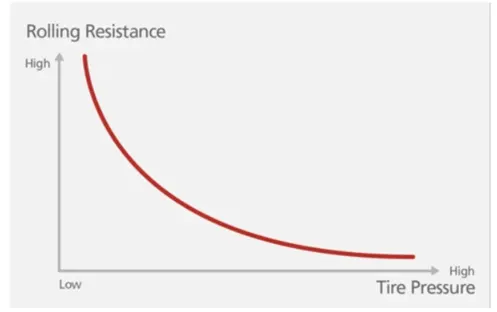
In the above image we can see the relation between rolling resistance and tyre pressure. As we mentioned earlier the value of coefficient of rolling resistance is related to tyre pressure in the graph we can see that they are inversely proportional. If value of tire pressure increases the value of rolling resistance decreases. If the value of rolling resistance increases the value of tire pressure decreases.
Brake forces when landing.
All modern aircraft are fitted with a braking system to assist in slowing and stopping when on the ground. Brakes are used not only to decelerate during a landing run, but also to hold the aircraft during an engine run-up, and in some cases to steer the aircraft through differential braking. Brakes are fitted to the main landing gear but not generally to the nose or tail wheel.
Physics of Braking
Brakes work by dissipating energy as heat through the action of friction. An aircraft wheel rotating at speed possesses a large amount of kinetic energy. By contacting the wheel with a semi-metallic or ceramic brake pad, an enormous amount of heat is generated as a result of the friction between the two contacting surfaces.
The large frictional forces generated during braking cause the pads to wear and so careful inspection and maintenance of the system is required to ensure the brakes continue to operate as designed.
Brakes are usually hydraulically actuated, but in some cases may be operated through a mechanical actuation system.
Brake Application
Traditionally, brakes are fitted to the upper half of the rudder pedals and are actuated through the pilot applying pressure to the top of each pedal. This toe-brake configuration is widely used and allows the pilot to apply differential braking by varying the pressure applied on each toe brake.
Many smaller light sport aircraft do not make use of toe brakes, preferring to use a simpler single lever mechanism. This lever is usually situated in the cockpit centre console and applies equal braking to all main wheels when engaged. The advantages of a single braking system include reduced complexity and lower part count when compared to toe-brakes. However, differential braking is clearly not possible with a single lever mechanism.
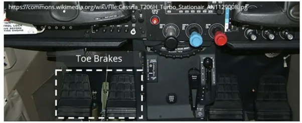
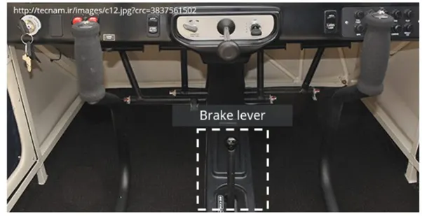
Most aircraft are fitted with a parking brake which can be applied through a switch or lever and will keep all brakes engaged when applied.
Types of Brakes
Disc Brakes
Disc brakes are the most common braking system in use today and consist of a disc which rotates with the wheel and a stationary brake calliper which actuates onto the disc to affect a braking force. The calliper is the name given to the assembly that contains the brake pads and piston(s). The pads are connected to the piston which actuates under hydraulic pressure applied either through a toe brake or a brake lever in the cockpit.
SINGLE DISC BRAKES
Smaller aircraft typically make use of a single disc sandwiched between two pads and attached to each main landing gear leg. The disc is fixed to the wheel so that it rotates as the wheel rotates. As the pilot applies the brakes, the calliper presses the pads against the disc braking the aircraft.
It is important that the frictional force applied by the callipers is uniform and evenly distributed. A typical braking system is designed with two callipers per disc; one calliper located on either side of the disc. The disc rotates with the wheel but is free to move laterally between the two sets of callipers. As the brakes are applied, the outer calliper moves inward towards the disc, contacting the disc and pushing it onto the inboard stationary calliper. In this way friction is applied evenly on both sides of the disc. When the brakes are released, a spring forces the piston to retract away from the disc, removing the braking action so that the disc is once again free to rotate. This disc brake configuration is called a floating disc brake as the disc is free to “float” laterally between the two callipers.
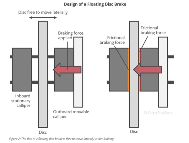
An alternate single disc arrangement used on light aircraft is the fixed disc brake arrangement. This works by fixing the disc rigidly to the wheel and allowing the callipers to move laterally as the brake is applied. Similar to the floating arrangement, this ensures that the brake pads apply an even braking force to the disc throughout the braking operation.
MULTIPLE DISC BRAKES
Larger, heavier aircraft with higher landing speeds are unable to extract sufficient braking force out of a single disc and calliper setup. The braking systems for these aircraft are designed with multiple sets of stationary steel discs (stators) sandwiched between copper or bronze rotors which rotate with the wheel. Hydraulic pressure applied to the stack of stators and rotors compresses the plates together, creating a large frictional force which brakes the aircraft.
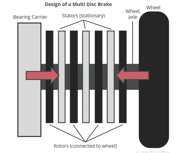
The design of a multiple disc and rotor systems has been improved over the years. The current state of the art for large aircraft is a segmented rotor-disc which operates in the same manner as above but with cut-outs in the plates for improved airflow and heat dissipation.
Recent improvements of segmented rotor-disc systems includes the use of carbon composite as the primary material from which to construct the rotors. Carbon fiber has improved heat dissipation characteristics when compared to steel, is stronger than steel, and does not fade at high temperatures. Carbon brakes also require less maintenance than traditional braking systems and are set to become the standard braking material in use for high performance braking applications.
All multi-disc systems require powerful hydraulic forces to actuate and control the systems. This is accomplished through a power brake or booster system which is discussed at the end of this post.
Expander Tube Brakes
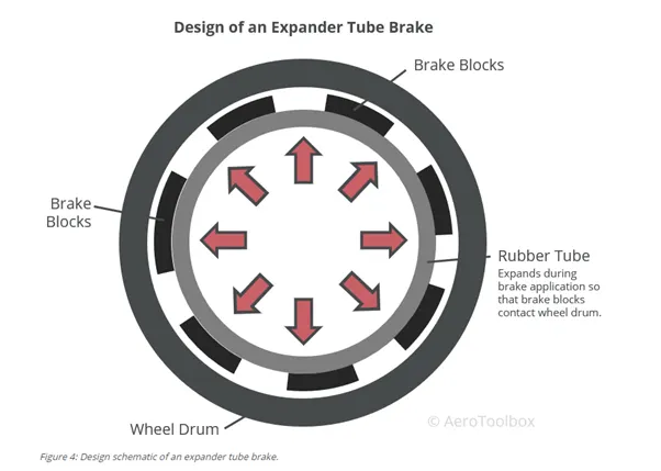
An older technology used predominantly on aircraft manufactured between 1930 and 1950, expander tube brakes are a low-pressure braking system that has now largely been replaced by disc brakes. The basic design consists of a lightweight frame attached to the outer section of a rubber tube. The frame and tube sit inside a wheel drum and a number of brake blocks are attached to the frame which provides the braking surface. The rubber tube is inflated during braking which pushes the brake pads onto the inside of a wheel drum, generating the friction necessary to slow the aircraft.
The tube is inflated through hydraulic action, where the effectiveness of the braking system can be varied through the hydraulic pressure developed. Springs installed in the system return the expander tube to its deflated position when braking force is removed by the pilot.
Brake Actuation Systems
Both disc brakes and the older expander tube type make use of a hydraulic system to actuate the brake pad onto the disc or drum. The hydraulic system that provides this actuation differs depending on the size and complexity of the aircraft. Three different systems are described below and cover the majority of brake actuations systems in use today.
Independent Brake System
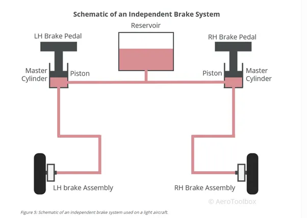
Light aircraft without a hydraulic system to actuate flaps, control surfaces, or landing gear make use of an independent hydraulic system to actuate the brakes. This stand-alone system consists of a reservoir, master cylinder connected to a brake pedal, and a piston in the brake calliper that actuates to apply the braking force.
When the pilot applies the brake pedal (independent toe-brakes or a single lever), the hydraulic fluid in the master cylinder is forced through the hydraulic lines to actuate the piston in the calliper. This pushes the pads onto the disc or drum, creating the friction necessary to slow the aircraft.
The applied braking force is a function of the force applied at the master cylinder. The harder the pilot applies the brake, the greater the braking pressure applied at the wheel. A typical braking system consists of two master cylinders (one for each toe brake) and two pistons that actuate under braking (one on each main gear leg). The reservoir may be remote and installed within the system or built into each master cylinder which removes the need for a separate reservoir unit.
Booster Brake System
An independent braking system does not make use of a mechanical pump to augment the pressure applied by the pilot by operating the brake. An aircraft fitted with a hydraulic system can boost the brake pressure by tapping the hydraulic system into the brake system. This hydraulic boost is only used under heavy braking and can increase the brake pressure to a value greater than that which can be applied by the pilot alone.
Brake booster systems are used on larger aircraft that require augmentation of the manual hydraulic braking system to slow the aircraft in a reasonable distance.
Power Brake System
Power braking systems are used on large aircraft where a manual or boosted system is insufficient to develop the hydraulic pressures required to arrest the aircraft. This system uses the aircraft’s hydraulic system as the sole source to apply the brakes. The pilot still controls the brakes through the toe-brakes on the rudder pedals, but the force produced is no longer a function of the strength of the pilot. Applying the brake opens a valve that allows fluid from the hydraulic system to enter the brake lines. The rate at which hydraulic fluid flows into the brake lines is regulated by the valve and is designed to give the pilot a “feel” for the braking action that is proportional to the force exerted on the brake pedal.
6) A. With necessary assumptions, calculate the force and power required to push / pull an aircraft by a towing vehicle.
Forces acting on the Aircraft and Towing vehicle
There are mainly two forces acting in the Towing condition:
- A) Rolling resistance force:
The Rolling resistance force is experienced by the tyres of the vehicle.
The rolling resistance force is given by the expression,
Frr = µrr*m*g
Where,
m= mass of the vehicle (kg)
g = gravity (9.81 m/sec^2)
urr- coefficient of rolling resistance.
Calculations:
1) For Aircraft:
Let us assume
Weight of the Aircraft = 500000 Kg
Coefficient Rolling Resistance for an Aircraft (urr) = 0.003
Hence,
Rolling resistance Force of Aircraft = µrr * m * g = 0.003*500000*9.81
= 14.715 KN
2) For Towing vehicle:
Let us assume,
Weight of the Towing tractor-50000 kg
Coefficient of Rolling Resistance of Towing vehicle (urr) = 0.003
Hence,
Rolling resistance force of towing vehicle = urr * m * g = 0.003*50000*9.81
Rolling resistance force of towing vehicle = 1.471 KN
Now,
Total Rolling Resistance Force = Rolling Resistance Force of aircraft + Rolling Resistance Force Towing vehicle
= 14.715 + 1.471
Total Rolling Resistance Force = 16.68 KN
- B) Air Drag Force:
The air drag force is the force experienced by the vehicle due to the air striking when moving
The Air Drag Force is given by:
Fad = 0.5 * p * A * v^2 * Cd
Where
p = density of air
A = frontal area of the vehicle on which the air strikes
V = velocity of the vehicle
Cd = Drag Coefficient
Calculations:
Here,
Density of Air (p) = 1.25 kg/m^3
Let us assume maximum speed.
The velocity of the Aircraft while Towing = 10 km/h = 2.77 m/s
1) For Aircraft:
Assume,
The frontal area of the Aircraft = 15 m²
The drag coefficient of the Aircraft = 0.1
Air drag force = 0.5 * p * A * v^2 * Cd
= 0.5*1.25*15*2.77^2*0.1
= 0.0071 KN
2) For Towing Vehicle
Assume
The frontal area of the Towing vehicle = 2 m²
The coefficient of Drag of the Towing vehicle = 0.8
Air drag force = 0.5 * p * A * v^2 * Cd
= 0.5*1.25*2*2.77^2*0.8
= 0.0153 kN
The total Air Drag force = Air Drag force of the aircraft +Air Drag force of the towing vehicle
0.0071 +0.0153 = 0.0224 KN
Hence,
The Total Force that the towing vehicle needs to overcome in order to pull the Aircraft = Total Rolling Resistance Force + The total Air Drag force
16.186 + 0.0224 = 16.208
Total Force required is 16.208 KN.
2) Power Required:
The maximum speed of Pull = 10 km/h = 2.77 m/s
Power required by the towing vehicle = Total Forces * Velocity = 16.208*2.77 m/s
Power required by the Towing vehicle = 44.89 kW.
B) Develop the model for the calculated force and power using Simulink.
The Simulink model is given below:
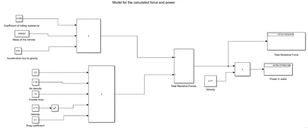
Constant blocks are used to feed the parameters such as mass, coefficients and other parameters
By using the product block the resistive forces are calculated.
By using sum block, total resistive forces can be calculated.
And the outputs are visualised using display blocks.
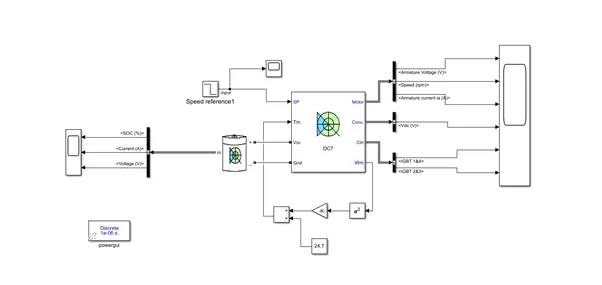
- A. Design an electric powertrain with type of motor, its power rating, and energy requirement to fulfill aircraft towing application in Simulink. Estimate the duty cycle range to control the aircraft speed from zero to highest. Make all required assumptions. Prepare a table of assumed parameters. Draw a block diagram of powertrain.
(Hint: DC7 Block)
B) Also, Design the parameters in excel sheet.
The Power Required for towing of the aircraft is 44.89kW.
Estimation of Duty Cycle:
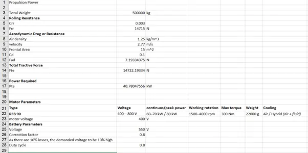
Based on the calculation done in question 6
Motor Considered for the drive train is REB 90
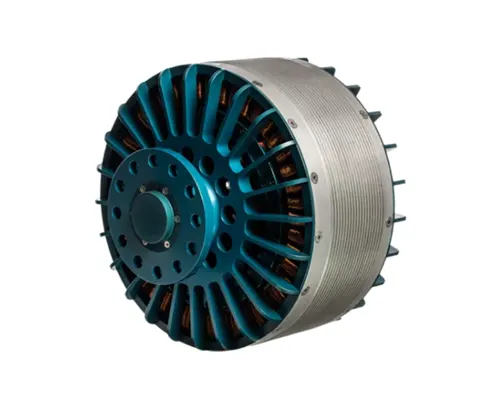

Considering 60kW as continuous power, so the voltage will be 400V Battery power is considered to be 550v
Duty cycle is given by Vo/Vb
where Vo is motor required voltage
Vb is battery voltage.
D = 400/550 id = 0.7272
As there will be losses due to the resistance of FET and Inductance.
Correction factor is considered to be 90%
As there is 10% loss, the voltage demanded by the motor should be 10% more than required
D = 0.7272*(1+0.1) = 0.799 nearly 0.8
so the voltage demand should be around 440V from the battery.
Assumed Parameters
Mass of aircraft = 500000 kg
Mass of the push back truck = 1000
Coefficient of Rolling Resistance = 0.003
Drag Coefficient = 0.1
Air density = 1.25 kg/m^3
Frontal Area = 15 m^2
Velocity = 2.77 m/s
Battery Voltage = 550V
Correction Factor = 0.8
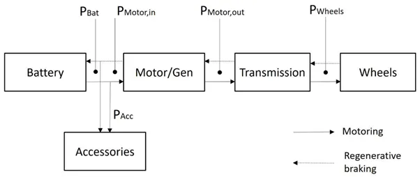
Block Diagram:
Simulink Model:
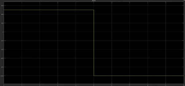
Input:
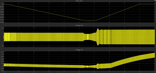
Output:
From the battery
From the motor
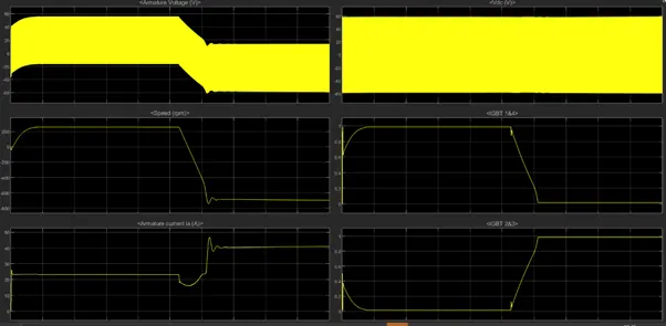
Start the simulation. You can observe the motor armature voltage and current, the four IGBT pulses, and the motor speed on the scope. The current and speed references are also shown.
The motor is coupled to a linear load, which means that the mechanical torque of the load is proportional to the speed.
The speed reference is set at 500 rpm at t = 0 s. Observe that the motor speed follows the reference ramp accurately.
The armature current follows the current reference very well, with fast response time and small ripples. Notice that the current ripple frequency is 5 kHz.
B) The design parameters in excel sheet is given below:
Ref - https://www.mgm-compro.com/other-products/electric-motors/