Week-6 Challenge: EV Drivetrain
Aim : -
1) Which types of power converter circuits are employed in electric and hybrid electric vehicle?
2)An Electric Vehicle's powertrain with 72V battery pack in shown in the diagram below. The duty ratio for acceleration operation is 'd1' and for the braking operation the duty ratio is 'd2'.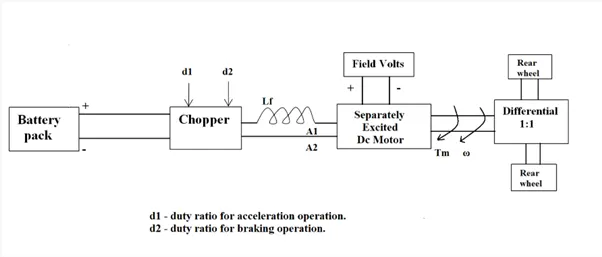
The other parameters of the electric vehicle is given below,
Motor and Controller Parameters:
Rated Armature voltage= 72 V
Rated armature current= 400 A
Ra= 0.5Ω, KΦ= 0.7 Volt second
Chopper Switching frequency= 400 Hz
The vehicle speed-torque characteristics are given by the below equation
Tv = 24.7+(0.0051)w^2
What is EV steady state speed if duty cycle is 70%?
3)Develop a mathematical model of a DC Motor for the below equation using Simulink.
w = V/KΦ – Ra/KΦ^2*T
4)Refer to the blog on below topic:
Induction Versus DC brushless motors by Wally Rippel, Tesla
Explain in brief about author’s perspective.
Solution : -
1)Which types of power converter circuits are employed in electric and hybrid electric vehicle?
The large number of automobiles in use around the world has caused and continues to cause serious problems of environment and human life. Air pollution, global warming, and the rapid depletion of the earth’s petroleum resources are now serious problems. Electric Vehicles (EVs), Hybrid Electric Vehicles (HEVs) and Fuel Cell Electric Vehicles (FCEVs) have been typically proposed to replace conventional vehicles in the near future.
Most electric and hybrid electric configurations use two energy storage devices, one with high energy storage capability, called the “main energy system” (MES), and the other with high power capability and reversibility, called the “rechargeable energy storage system” (RESS). MES provides extended driving range, and RESS provides good acceleration and regenerative braking.
Energy storage or supply devices vary their output voltage with load or state of charge and the high voltage of the DC-link create major challenges for vehicle designers when integrating energy storage / supply devices with a traction drive.
DC-DC converters can be used to interface the elements in the electric power train by boosting or chopping the voltage levels. Due to the automotive constraints, the power converter structure has to be reliable, lightweight, small volume, with high efficiency, low electromagnetic interference and low current/voltage ripple.
An Electric Vehicle is a vehicle that uses a combination of different energy sources, Fuel Cells (FCs), Batteries and Supercapacitors (SCs) to power an electric drive system as shown in Fig. In EV the main energy source is assisted by one or more energy storage devices. Thereby the system cost, mass, and volume can be decreased, and a significant better performance can be obtained. Two often used energy storage devices are batteries and SCS. They can be connected to the fuel cell stack in many ways. A simple configuration is to directly connect two devices in parallel, (FC/battery, FC/SC, or battery/SC). However, in this way the power drawn from each device cannot be controlled, but is passively determined by the impedance of the devices. The impedance depends on many parameters, e.g. temperature, state-of-charge, health, and point of operation. Each device might therefore be operated at an inappropriate condition, e.g. health and efficiency. The voltage characteristics also have to match perfectly of the two devices, and only a fraction of the range of operation of the devices can be utilized, e.g. in a fuel cell battery configuration the fuel cell must provide almost the same power all the time due to the fixed voltage of the battery, and in a battery/supercapacitor configuration only a fraction of the energy exchange capability of the supercapacitor can be used. This is again due to the nearly constant voltage of the battery. By introducing DC/DC converters one can chose the voltage variation of the devices and the power of each device can be controlled (Schaltz & Rasmussen, 2008).
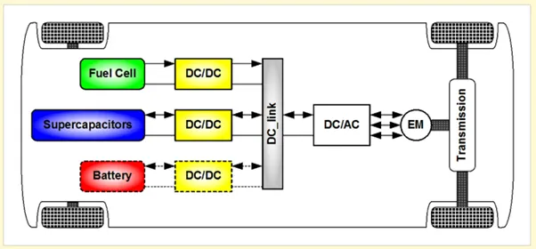
In reference (Schaltz & Rasmussen, 2008), 10 cases of combining the fuel cell with the battery, SCs, or both are investigated. The system volume, mass, efficiency, and battery lifetime were compared. It is concluded that when SCs are the only energy storage device the system becomes too big and heavy. A fuel cell/battery/supercapacitors hybrid provides the longest life time of the batteries. It can be noticed that the use of high power DC/DC converters is necessary for EV power supply system. The power of the DC/DC converter depends on the characteristics of the vehicle such as top speed, acceleration time from 0 to 100 Km/h, weight, maximum torque, and power profile (peak power, continuous power) . Generally, for passenger cars, the power of the converter is more than 20 KW and it can go up to 100 KW.
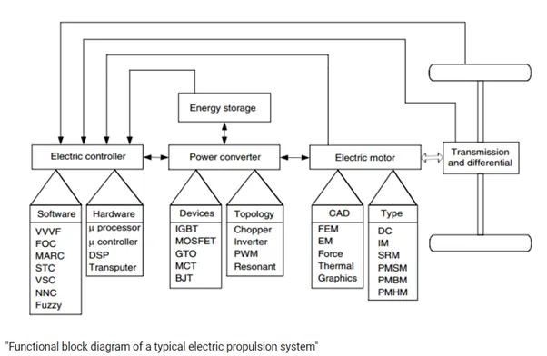
In electric engineering, a DC to DC converter is a category of power converters and it is an electric circuit which converts a source of direct current (DC) from one voltage level to another, by storing the input energy temporarily and then releasing that energy to the output at a different voltage. The storage may be in either magnetic field storage components (inductors, transformers) or electric field storage components (capacitors).
DC/DC converters can be designed to transfer power in only one direction, from the input to the output. However, almost all DC/DC converter topologies can be made bi-directional. A bi-directional converter can move power in either direction, which is useful in applications requiring regenerative braking.
The amount of power flow between the input and the output can be controlled by adjusting the duty cycle (ratio of on/off time of the switch). Usually, this is done to control the output voltage, the input current, the output current, or to maintain a constant power. Transformer-based converters may provide isolation between the input and the output.
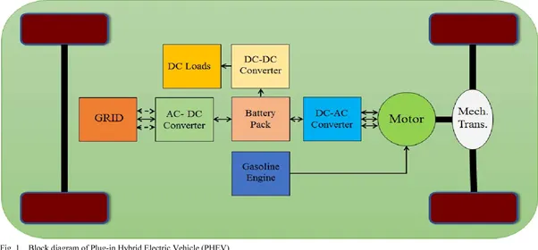
Broadly speaking, an inverter is an electrical device that converts electricity derived from a DC (Direct Current) source to AC (Alternating Current) of the type that can be used to drive a device or appliance. In a solar power system, for example, the power stored by batteries charged by solar panels is converted to standard AC power by the inverter, which provides the power to plug-in outlets and other standard 120-volt devices. An inverter serves the same kind of function in a hybrid or EV car, and the theory of operation is relatively simple.
DC power, from a hybrid battery, for example, is fed to the primary winding in a transformer within the inverter housing. Through an electronic switch (generally a set of semiconductor transistors), the direction of the flow of current is continuously and regularly flip-flopped (the electrical charge travels into the primary winding, then abruptly reverses and flows back out). The in/outflow of electricity produces AC current in the transformer's secondary winding circuit. Ultimately, this induced alternating current electricity provides power for an AC load—for example, an electric vehicle's (EV) electric traction motor.
A rectifier is a similar device to an inverter except that it does the opposite, converting AC power to DC power.
Ref - https://www.intechopen.com/chapters/19583
2)An Electric Vehicle's powertrain with 72V battery pack in shown in the diagram below. The duty ratio for acceleration operation is 'd1' and for the braking operation the duty ratio is 'd2'.
The other parameters of the electric vehicle is given below,
Motor and Controller Parameters:
Rated Armature voltage= 72 V
Rated armature current= 400 A
Ra= 0.5Ω, KΦ= 0.7 Volt second
Chopper Switching frequency= 400 Hz
The vehicle speed-torque characteristics are given by the below equation
Tv = 24.7+(0.0051)w^2
What is EV steady state speed if duty cycle is 70%?
We have ,
Rated Armature voltage= 72 V
Rated armature current= 400 A
Ra= 0.5Ω, KΦ= 0.7 Volt second
Chopper Switching frequency= 400 Hz
Tv = 24.7+(0.0051)w^2
Here Tm=Tl
Now, Speed torque equation of motor is –
w = V/KΦ-Ra/KΦ^2*Tm
For the value of V we need to multiply the armature voltage with duty cycle.
Therefore, V = 72*(70/100) = 50.4 V
By substituting this value in speed torque equation we get ,
w = 50.4/0.7 – 0.5/0.49*Tm
w = 72 – 1.02Tm
1.02Tm = 72-w
Tm = 72/1.02 – w/1.02
Tm = 70.58 – 0.98w
We have given the vehicle speed-torque characteristics by the below equation
Tv = 24.7+(0.0051)w^2
Where Tv is the torque of the vehicle .
At steady state the Tv = Tm
By substituting the equation we get,
24.7+(0.0051)w^2 = 70.58 – 0.98w
w = 32.98 w = -231.07
thus the vehicle steady state speed is 32.98 because it moves in forward direction.
3)Develop a mathematical model of a DC Motor for the below equation using Simulink.
w = V/KΦ – Ra/KΦ^2*T
To develop a mathematical model we take,
V = 80 v
KΦ=0.5
Ra=0.7
T=10
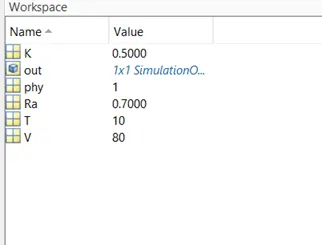
First of all take three constant blocks then put values of variables in command window and you might see the values in the workspace .
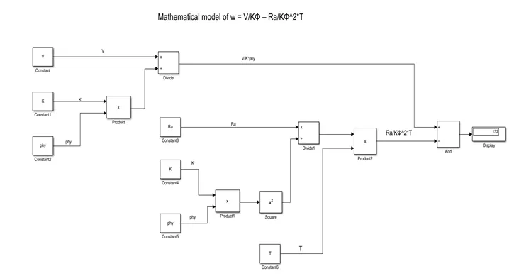
The V is connect to divide block and the K*phy are connected to product block and they further connected to divide block. Now Ra is connected to divide block and k*phy^2 is connected to product block and it further will connected to divide block. T is connected to product block with k*phy^2. Now V/KΦ is connected to add block with positive sign and the Ra/KΦ^2*T is connected to negative sign. And we get the result is 132.
4) Refer to the blog on below topic:
Induction Versus DC brushless motors by Wally Rippel, Tesla
Explain in brief about author’s perspective.
According to the blog “ Induction motor vs Dc brushless motor” by Wally Rippel Tesla the author give the idea that which motor is good and efficient for ev technology.
With the DC brushless motor, the rotor inside incorporates two or more permanent magnets that generate a DC magnetic field. This magnetic field enters the stator core and interacts with the voltage/current within the windings to produce a twisting force between the two (torque). As the rotor spins, the current within the stator has to have its magnitude and current constantly monitored and varied to optimize both torque and efficiency. This control unit is called an inverter and it is the drive brain of the motor.
The induction motor is very different and at the same time very similar. Nikola Tesla invented the induction motor in the 1880s.
His motor, when connected to three phase AC power will spin at a constant speed. The primary difference is the absence of magnets within the motor. Both have rotors, both have stator cores, and both have distributed windings. The magnets within the rotor of the DC brushless motor are replaced with stacked laminations of steel or a squirrel cage rotor in the induction motor..
Currents within the stator windings produce a rotating magnetic field and the rotor reacts accordingly by applying a rotational force. Of course, there is a lot of engineering that goes into monitoring and application of current, voltage peak-to-peak, and frequency in these motors to maintain the optimal torque and power at any given speed. This brain is also called an inverter.
In the DC brushless drive the magnetic field produced by the permanent magnets is constant. This puts the motor at a disadvantage where peak performance at all times is required.
In the induction motor, this magnetic field is adjustable by changing voltage, frequency, and current to maintain optimal torque and performance at all speeds.
Tesla Motors was the first to innovate with the introduction of the AC induction motor.
DC brushless motor would be falling behind, but currently there is no real advantage leader between the two. In the DC brushless motor it comes down to efficiency-it is the efficiency king. When this motor is running in its happy place, it can top 96% efficiency turning that applied electricity into electromotive force. When coupled with a multi speed transmission to keep it in that happy place, it is the efficiency champ.
Meanwhile, the induction motor's big advantage apart from its simplicity and ruggedness has always been its ability to tolerate a wider range of temperatures and speeds, Providing adequate cooling for the Toyota Prius' permanent magnet motor adds significantly to the vehicle's weight. An induction motor, by contrast, can be cooled passively-thereby dispensing with the hefty radiator, cooling fan, water pump, and associated plumbing.
The difference here is that the induction motor applies AC voltage to each of the windings in succession, and the DC brushless motor applies pulsed DC to each of the windings in succession the speed of the rotation depending on the frequency of the applied voltage to each of the poles-the higher the frequency the faster the rotor spins.
Conclusion
All in all, both motors are quite good at doing what they were designed to do. The DC brushless motors have been around a little longer in this application and have a strong foothold in the industry, but that foothold is slipping as the technology to control the induction motor has improved.
Conclusion : -
1) We studied different types of converters that we used in hybrid and electrical vehicles.
2) Thus we get the vehicle steady state speed is 32.98 because it moves in forward direction.
3) As per equation the model is built and the o/p of the model is 132.
4) Both motors are quite good at doing what they were designed to do. The DC brushless motors have been around a little longer in this application and have a strong foothold in the industry, but that foothold is slipping as the technology to control the induction motor has improved.