Project-1: Powertrain for aircraft in runways
1. Search and list out the total weight of various types of aircrafts.
A cargo aircraft (also known as freight aircraft, freighter, airlifter or cargo jet) is a fixed wing aircraft that is designed or converted for the carriage of cargo rather than passengers. Such aircraft usually do not incorporate passenger amenities and generally feature one or more large doors for loading cargo. Freighters may be operated by civil passenger or cargo by private individuals or by the armed force of individual countries.
Aircraft designed for cargo flight usually have features that distinguish them from conventional passenger aircraft: a wide/tall fuselage cross-section, a highwing to allow the cargo area to sit near the ground, numerous wheels to allow it to land at unprepared locations, and a high-mounted tail to allow cargo to be driven directly into and off the aircraft.
some of the examples for cargo type planes and their weights are
| Aircraft | Volume | Payload |
|---|---|---|
| Antonov An-124 | 1028 m3 | 150,000 kg (331,000 lb) |
| Antonov An-225 | 1300 m3 | 250,000 kg (551,000 lb) |
| Boeing C-17 | – | 77,519 kg (170,900 lb) |
| Boeing 737-700C | 107.6 m3 | 18,200 kg (40,000 lb) |
Agricultural aircraft:
An agricultural aircraft is an aircraft that has been built or converted for agricultural use – usually aerial application of pestiides or fertilizer in these roles they are referred to as "crop dusters" or "top dressers". Agricultural aircraft are also used for hydroseeding.
The most common agricultural aircraft are fixed wing, such as the air tractors but helicopters are also used.
Generally agricultural aircraft have piston or turboprop engines.
with fully loaded
| 9,495 lbs (4.306 kg) |
fighter aircraft:
Fighter aircraft are fixed wing designed primarily for air to air combat In military conflict, the role of fighter aircraft is to establish of the battle space. Domination of the airspace above a battlefield permits bombers and attack aircraft to engage in tactical and bombing of enemy targets.
The key performance features of a fighter include not only its firepower but also its high speed and manevarubility relative to the target aircraft. The success or failure of a combatant's efforts to gain air superiority hinges on several factors including the skill of its pilots, the tactical soundness of its doctrine for deploying its fighters, and the numbers and performance of those fighters.
| 45,000 lb (20, 411 kg) class 81,000 lb (36, 700 kg) max gross takeoff |
glider:
A glider is a fixed wing that is supported in flight by the dynamic reaction of the air against its lifting surfaces, and whose free flight does not depend on an engine.[1] Most gliders do not have an engine, although motor gliders have small engines for extending their flight when necessary by sustaining the altitude (normally a sailplane relies on rising air to maintain altitude) with some being powerful enough to take off self launch.
glider aircraft weight
| 1,100 lb |
airship:
An airship or dirigible balloon is a type of aerostat or lighter-than-air aircraft that can navigate through the air under its own power. Aerostats gain their lift from a lifting gas that is less dense than the surrounding air.
airship weight with fuel and equipemt is comes to around 10000kgs
(2)
Air speed is how fast the aircrft is moving thorugh the air.
Ground speed is how fast the aircraft is moving over the ground.
The difference is that the air is moving. An aircraft with an airspeed of 100mph going the same direction as a flow of air moving 50mph has a ground speed of 150 mph. If the same aircraft makes a 180 degree turn and heads directly into the wind, the airspeed stays at 100mph but the grounspeed drops to 50 mph.
Same rules apply to all aircraft, private, commercial, or military.
(3)
Towing
The forward movement of an aircraft, usually with engines off, using the power of a specialised ground vehicle attached to or supporting the nose landing gear. It may occur for the movement of both in service and out of service aircraft. This will affect the promulgation of procedures and the required qualification for those occupying the flight crew seats on the aircraft during the manoeuvre. As part of out of service repositioning of aircraft supervised by maintenance personnel, it may follow the pushback from a nose-in gate of an empty aircraft with engines off.
although most of the aircraft move backwards,but most of time they are not used due to
- the jet blast from the engine can damage the terminal building and any near by equipment even it can throw people away near by.
- engines can blow sand and debris
- sand can enter into the engines which causes engine damage
- it is easier to truck driver to lookaround the airport than pilot sitting in cockpit with limited windows.
- truck driver knows well about the airport than the pilot.
- people sitting in the terminal or in airport will get loud engines noises when more aeroplanes are starting their engines
(4)
Taxing
taxiing is the movement of aircraft on the ground,under its own power.in contrast to towing or pushback where the aircraft is moved by a tug.An airplane uses taxiways to taxi from one place on an airport to another; for example, when moving from a hangar to the runway.
When taxiing, aircraft travel slowly. This ensures that they can be stopped quickly and do not risk wheel damage on larger aircraft if they accidentally turn off the paved surface. Taxi speeds are typically 30 to 35 km/h.
(5) take off:
A normal takeoff is one in which the airplane is headed into the wind; there are times that a takeoff with a tail wind is necessary. However, the pilot must consult the POH/AFM to ensure the aircraft is approved for a takeoff with a tail
wind and that there is sufficient performance and runway length for the takeoff. Also, the takeoff surfaces are firm
and of sufficient length to permit the airplane to gradually accelerate to normal lift-off and climb-out speed, and there
are no obstructions along the takeoff path.
There are two reasons for making a takeoff as nearly intothe wind as possible. First, since the airplane depends on
airspeed, a headwind provides some of that airspeed even before the airplane begins to accelerate into the wind. Second,
a headwind decreases the ground speed necessary to achieve flying speed. Slower ground speeds yield shorter ground rolldistances and allow use of shorter runways while reducing wear and stress on the landing gear.
tyre design:
When it comes to safety, tyres are one of the most important components of aircraft. They help to absorb the shock of landing and provide cushioning. It also provides the necessary traction for braking and stopping of an aircraft.
An aircraft tyre is designed to withstand extremely heavy loads while landing, take off, taxing, and parking. The number of wheels required for aircraft increases with the weight of the aircraft, as the weight of the aeroplane needs to be distributed more evenly.
urpose it serves.
- They support the weight of an aircraft while it is on the ground.
- It also provides the necessary traction for braking and stopping of an aeroplane.
- Tyre also helps to absorb the shock of landing and provide cushioning the roughness of takeoff, roll-out, and taxi operations.
Unlike an automobile or truck tyre, it does not have to carry a load for a long period of continuous operation. However, an aircraft tyre absorbs the high impact loads of landing, and also it’s operating at high speeds for a short time when required.
rolling resistance:
the friction between aircraft and runway will be proportional to normal force exerted by aircraft on the runway.
`F=mu*W-L`
Tyre pressure:
An aircraft tire or tyre is designed to withstand extremely heavy loads for short durations.The number of tires required for aircraft increases with the weight of the aircraft, as the weight of the airplane needs to be disributed more evenly. Aircraft tire tread patterns are designed to facilitate stability in high crosswind conditions, to channel water away to prevent hydroplanning and for braking effect.
Aircraft tires generally operate at high pressures, up to 200 psi (14 bar; 1,400 kPa) for airliners, and even higher for business jets. The main landing gear on the Concorde was typically inflated to 232 psi (16.0 bar), whilst its tail bumper gear tires were as high as 294 psi (20.3 bar).
Brake forces when landing:
stopping a 200-tonne aircraft landing at 180 mph requires a lot of braking force. To do this, the 787 has one brake unit on each of the eight wheels on the main gear assembly. On other aircraft types, the brake units are powered by the hydraulics system. An electrical signal is sent from the flight deck to hydraulic actuators near the main landing gear. Here, hydraulic fluid at 3,000 pound per square inch is used to force the brake unit against the wheel, thus slowing it down.
Aircraft brakes stop a moving aircraft by converting its kinetic energy to heat energy by means of friction between rotating and stationary discs located in brake assemblies in the wheels.
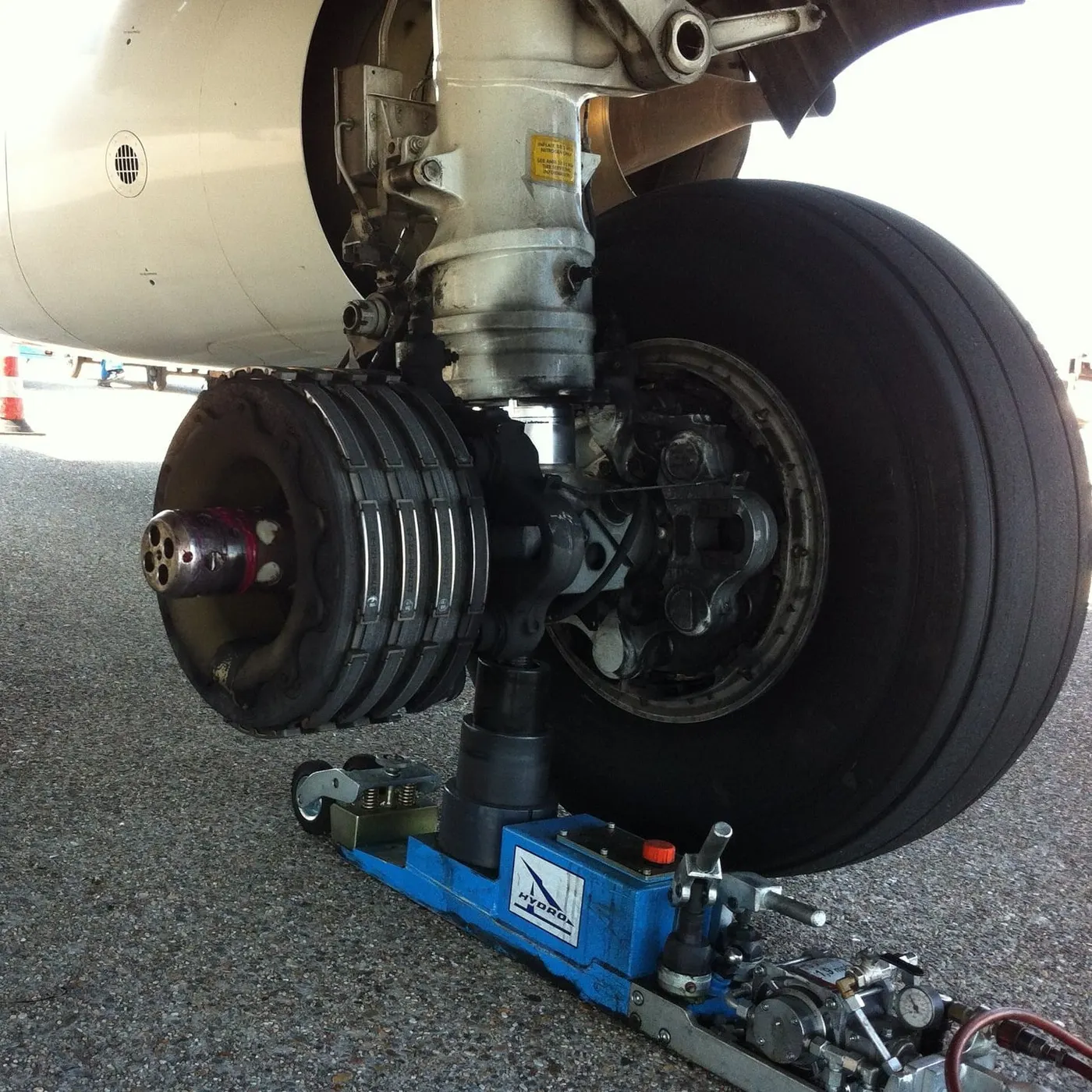
Brakes provide this critical stopping function during landings to enable airplanes to stop within the length of the runway. They also stop aircraft during rejected takeoff events, in which an attempted takeoff is canceled as the airplane is rolling down the runway before it lifts off from the ground due to engine failure, tire blowout, other system failure or direction from air traffic control.
brakes also prevent motion of the aircraft when it is parked, limit its speed during taxiing and can even help steer the aircraft on the ground by applying different levels of braking force to the left- and right-side brakes.
The most common type of brake used on aircraft is the disc brake. function by exploiting friction between rotating and stationary discs inside the brake.
Upon receiving a command signal to brake — from the pilot depressing a foot pedal or from the autobrake system — actuators in the brake move a piston to squeeze the discs together, generating a frictional force that slows the rotation of the The friction between the discs generates heat as the aircraft’s kinetic energy is converted to heat energy. In this function, the brakes act as a heat sink, absorbing tremendous amounts of heat as the aircraft sheds kinetic energy. During RTO stops, the temperature of carbon disc brakes can exceed 1,800° C.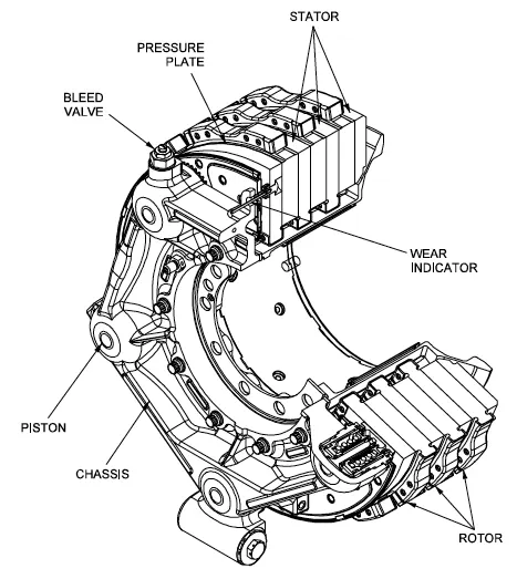 Gulfstream G450 main landing gear brake assembly. Source: G450 Maintenance Manual via Code 7700
The discs are mounted on a carrier assembly consisting of a torque tube, which resists and transmits brake torque to the structure. Sandwiched together between the carrier assembly housing and a backing plate, the discs are arranged in an alternating pattern of rotors and stators. Notch and groove geometry around the circumference of each rotor fits into corresponding geometry in the wheel, keying the rotors to the wheel so that they rotate with it. The stators are keyed to the torque tube and are thus held stationary since the torque tube is connected to the axle and landing gear structure.Cylindrical spaces within the carrier assembly hold Braking occurs as piston force squeezes the discs togetherDuring each application of the brakes, disc material is worn away by frictional forces. A wear indicator in the form of a pin that protrudes out of the carrier assembly indicates the thickness of the stack of discs. Over hundreds of brake applications, material wears away and discs become thinner, requiring replacement following periodic maintenance intervals.
6. A. With necessary assumptions, calculate the force and power required to push / pull an aircraft by a towing vehicle.
(1)rolling resistance force (2)aerodynamic force
rolling resistance force:
the formula used for rolling resistance force is `Frr=u*m*g`
rolling resistance force is acted on both truck and airplane
so u=0.02,m=40000kg
aircraft Frr=0.02*40000*9.81=7848n
now for pushback truck u=0.08,1000kg
frr=0.08*1000*9.81=883n
now 7848+883=8731n
7. A. Design an electric powertrain with type of motor, it’s power rating, and energy requirement to fulfill aircraft towing application in Simulink. Estimate the duty cycle range to control the aircraft speed from zero to highest. Make all required assumptions. Prepare a table of assumed parameters. Draw a block diagram of powertrain.
Description
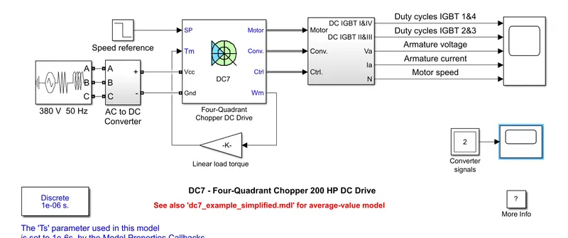
The 200 HP DC motor is separately excited with a constant 150 V DC field voltage source. The armature voltage is provided by an IGBT converter controlled by two PI regulators. The converter is fed by a 515 V DC bus obtained by rectification of a 380 V AC 50 Hz voltage source. In order to limit the DC bus voltage during dynamic braking mode, a braking chopper has been added between the diode rectifier and the DC7 block.
The first regulator is a speed regulator, followed by a current regulator. The speed regulator outputs the armature current reference (in p.u.) used by the current controller in order to obtain the electromagnetic torque needed to reach the desired speed. The speed reference change rate follows acceleration and deceleration ramps in order to avoid sudden reference changes that could cause armature over-current and destabilize the system. The current regulator controls the armature current by computing the appropriate duty ratios of the 5 kHz pulses of the four IGBT devices (Pulse Width Modulation). For proper system behaviour, the instantaneous pulse values of IGBT devices 1 and 4 are opposite to those of IGBT devices 2 and 3. This generates the average armature voltage needed to obtain the desired armature current. In order to limit the amplitude of the current oscillations, a smoothing inductance is placed in series with the armature circuit.
Simulation
Before starting the simulation, set the initial bus voltage to 515 V via the GUI block ('Initial States Setting' button and 'Cbus' variable).
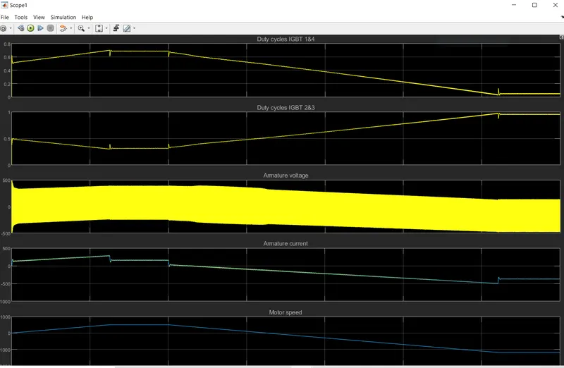
Start the simulation. You can observe the motor armature voltage and current, the four IGBT pulses and the motor speed on the scope. The current and speed references are also shown.
The motor is coupled to a linear load, which means that the mechanical torque of the load is proportional to the speed.
The speed reference is set at 500 rpm at t = 0 s. Observe that the motor speed follows the reference ramp accurately (+400 rpm/s) and reaches steady state around t = 1.3 s.
The armature current follows the current reference very well, with fast response time and small ripples. Notice that the current ripple frequency is 5 kHz.
At t = 2 s, speed reference drops to -1184 rpm. The current reference decreases to reduce the electromagnetic torque and causes the motor to decelerate with the help of the load torque.
At t = 2.2 s, the current reverses in order to produce a braking electromagnetic torque (dynamic braking mode). This causes the DC bus voltage to increase.
At t = 3.25 s, the motor reaches 0 rpm and the load torque reverses and becomes negative. The negative current now produces an accelerating electromagnetic torque to allow the motor to follow the negative speed ramp (-400 rpm/s). At t = 6.3 s, the speed reaches -1184 rpm and stabilizes around its reference.
input:
electric powertrain has three main components:
battery..powerconerter..motor
motor design:
the elecrtic tug assumed to have a gear ratio of 1:10.thus the torque produced my multiple motor is multiplied by a factor of 10 at wheels.
torque required for the wheels of aircraft=1889.11nm
required motor toruqe=1889.11/10=188.911nm
assumptions made:
motor loss:10%
transmission losses=20%
required motor toruqe=188.9+188.9(0.1+0.2)=245nm
power calculation:
the power required =19.12kw
assumptions:
motor efficiency=90%
motor to run at 80% of the full capacity for safety purpose
required motor power=19.12/0.9*0.8=26.5kw
torque rating =245nm
power rating=35hp
power converter:
required power is 26.52kw and the motors power is 41kw
duty cycle caluclation=26.52/41=0.64
the duty cycle range is 0 to 0.64%
battery capacity:
average time is 10min
energy=power*time*60=26.5*10*60=15900kj
converting into 4.4167kwh
for 10min tug required is 4.4167kwh for this additional 0.6kwh is added 4.4+0.6=5.0kwh
for single battery can perform up to 25 towing operations
5.0*25=125kwh
battery capacity is =125kwh
capacity is 41kw