Project-1: Powertrain for aircraft in runways
1. The various weights that are responsible for total weight of aircrafts are:
- Aircraft Gross weight
Aircraft gross weight is defined as the total aircraft weight at any moment during the flight or ground operation. During the flight the aircraft's gross weight will decrease due to fuel and oil consumption.
- Maximum Ramp weight
Maximum ramp weight is defined as the maximum weight authorised for moving (towing) the aircraft on the ground
- MaximumLanding weight
Maximum landing weight is defined as the maximum weight at which the aircraft is permitted to land
- Maximum take off weight
Maximum take off weight is defined as the maximum weight at which the pilot is allowed to attempt to take off.
- Payload
Payload is the carrying capacity of the aircraft which is usually measured in terms of weight. Payload includes cargo, passengers, crew members, scientific instruments and extra fuel.
- Operating empty weight (OEW).
Operating empty weight is the sum of the empty weight and the crew and includes the baggage. It also includes the fluids necessary for operation such as engine coolant, water, hydraulic fluid and unusable fuel. It excludes usable fluid and payload.
- Zero fuel weight
Zero fuel weight is defined as the total weight of the aircraft which includes all its contents but excludes the total weight of the usable fuel on board. As the flight progresses fuel is consumed, the total weight of the plane reduces, but the zero-fuel weight remains constant.
Types of Aircrafts and their weights:
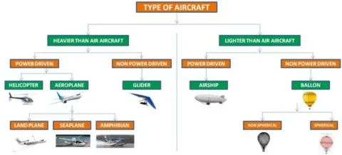
Airplane:
The Boeing 737-800 has a maximum takeoff weight of about 80,000 kg (175,000 lbs) which includes the weight of the plane is 41,000 kg (90,000 lbs), the weight of the fuel is 18,000 kg (40,000 lbs) and leaves about 20,000 kg (45,000 lbs) for passengers, cargo, and crew.
Helicopter:
A helicopter can weigh as little as 298 pounds (135 kg), up to as much as 33,230 pounds (15,070 kg), in empty weight. The weight of a helicopter varies by the type, model, and primary use intended for the aircraft.
Glider:
most single-seat gliders with 15m wingspans have empty weights around 250kg(550 lbs). The pilot and their equipment typically add around 100kg (220 lbs).
Airship:
Without its lifting gas, an empty Blimp weighs almost 20,000 lbs. Once inflated with helium and after accounting for fuel, payload, and ballast, it usually weighs in at 100-200 lbs.
Air ballon:
A typical hot-air balloon has a total mass of 545 kg, including passengers in its basket, and holds 2.55 x 10' m' of hot air in its envelope.
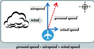
Difference between Ground speed and Air speed .
Ground Speed
Ground speed is aircraft speed realtive to ground. Ground speed is how fast an airplane's shadow would move across the land.
If there's a strong wind pushing an aircraft, that's reflected in the ground speed. Ground Speed is the vector sum of air speed and the wind speed.
Ground Speed = Air Speed + Wind Speed
Air Speed
The quantity in the generation of lift is the relative velocity between the object and the air, which is called the airspeed. Airspeed cannot be directly measured from a ground position, but must be computed from the ground speed and the wind speed. Airspeed is the vector
difference between the ground speed and the wind speed.
Air Speed = Ground Speed - Wind Speed
3. Reasons for not using aircraft engine power to move it on the ground at Airport
- Usage of high power mounted engines have high risk of blasting which might cause damage to the terminal building or equipment.
- There is also a risk of injury to ground support personnel who may be in relatively close proximity to the aircraft.
- Engines close to the ground may also blow sand and risk of impurities may enter inside the engine. Thus effectively a loss of control can happen and not only damage the aircraft itself but also other aircraft nearby or to airside structures.
- A Pushback is therefore the preferred method to move the aircraft away from the gate . It can reduce the cost for fuel and reduce impact of environment.
- It is easier for tug vehicle driver to see the surroundings better than the pilot sitting in the cockpit with limited window.
- The plane engines are very loud. When more than one plane will add up their sound, than it will not be pleasent for passangers and others near airport.
4. How aircraft is pushed to Runway when its ready to take off
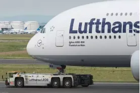
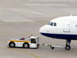
- The aircraft is pushed back from the terminal gate once the clearance is obtained from the flight control.
- A Pushback truck reverses the aircraft into taxiing position,by pushing it with a towbar attached to nose-wheel or by actually lifting the wheel.
- Then the aircraft is pushed away to a safe place because there are several dangers that can exist when the aircraft uses the thrust from the jet engine for movement in the ground.
- Then aircraft is ready for taxiing. An airplane uses taxiways to taxi from one place on an airport to another, for example, when moving from a hangar to the runway.
- The engines are started only when the truck is removed and all platform staff is out of the way and aircraft moves on its own power. The aircraft then moves at a slow speed for safety reasons to the start of the runway.
5.
Take off Power
- Takeoff is the phase of flight in which an aircraft goes through a transition from moving along the ground to flying in the air, usually starting on a runway.
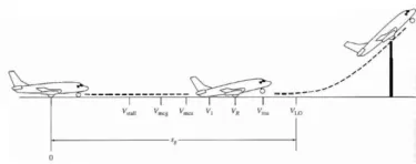
- As the airplane accelerates from zero velocity, it will reach the stalling velocity VStalland then continues to accelerate until it reaches the minimum control speed on the ground, Vmcg.
- The minimum speed required for yaw control that is slightly greater than Vmcg is known as the minimum control speed in the air, Vmca
- Thenairplane reaches the decision speed V1, the speed at which the pilot can successfully takeoff even an engine fails e., in a multiengine aircraft. If an engine fails before V1 is achieved, the takeoff must be stopped.
- Then it reaches the takeoffRotational speed VR, at which the pilot initiates the airplane in order to increase the angle of attack at which the nose pitch up.
- Lift off speed, denoted by VLO is the point at which the airplane actually lifts off the ground.
- The total distance covered along the ground to this point is the ground roll Sg.
During the take-off run, the forces that produce an acceleration along the runway.
m*(dv/dt)=T-D-F
where,
dv/dt is the acceleration along the runway
m is the mass of the vehicle.
Tis Thrust of propulsion system pushing aircraft along the runway.
D is Aerodynamic Drag of vehicle resisting the aircraft motion.
Fis Rolling resistance friction due to the contact of wheels or skids on the ground.
Take Off power = force*displacement
(m*(dv/dt)) * Sg = (T-D-F) * Sg
Tyre design
- Tyre is important component of an aircraft in terms of safety. Tyres help to absorb the shock of landing and provides cushion. It also provides the necessary traction for braking and stopping the aircraft.
- The aircraft is designed in such a way that the aircraft will be able to withstand extremely heavy loads while landing, take off, taxing and parking.
- The number of wheels required for aircraft increases with the weight of the aircraft as the weight of the aircraft needs to be more evenly distributed.
- Carcass piles are used to form the tyres which are commonly known as casing piles.
- Bias and Radial types are the tyres used in aircraft. Almost all airliners are using Radial tyre. Bias is an older design, and it’s mainly used for road vehicles.Radial tires are more expensive than bias-ply tyres. Radial tires are in demand because of their lower life cycle cost and long term value.
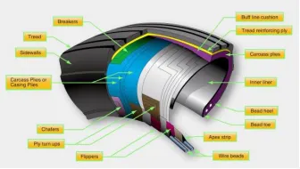
Technical aspects of the tyre
- Retreading
Retreading is a method of restoring a worn tyre by renewing the tread area and also renewing one or both sidewalls.
- Load rating
Load rating is the maximum permissible load at a specified inflation pressure.
- Ply rating
Ply rating is used to identify the maximum recommended load rating and inflation pressure for a specified tyre.
- Speed rating
Speed rating is the maximum take-off speed to which the tyre has been tested.
- Skid depth
Skid depth is defined as the distance between tread surface and deepest groove as measured in the mould.
Rolling resistance
Rolling resistance is the force that resists the motion when the body rolls on the surface. Rolling resistance action takes in aircraft when it takes off from the runway and when landing on runway.
It is represented by the following equation:
Frr = `mu`rr mg
Where,
Frr = rolling resistance force (N)
`mu`rr = coefficient of rolling resistance
m = Total mass of the vehicle (kg)
g = Acceleration due to gravity (m/s2)
Tyre pressure
- Aircraft tires are usually inflated with nitrogen to minimize expansion and contraction from extreme changes in ambient temperature and pressure experienced during flight.
- The typical airline tyre can handle a 38-ton load. Aircraft tires generally operate at high pressures, up to 200 psi (14 bar; 1,400 kPa) for airline, and even higher for business jets.
- The main landing gear was typically inflated to 232 psi (16.0 bar), whilst its tail bumper gear tires were as high as 294 psi (20.3 bar).
- Aircraft tyres operate at such high extremes of pressure, load, and speed, their care and service is critically important.
- The most important action taken to prevent tyre-related events is to maintain proper tire inflation pressure. Failure to keep aircraft tires properly inflated can lead to very serious consequences.
- One relatively easy way to help avoid those consequences is to check tire pressures regularly and service them as necessary.
- The above measures contribute the most value out of tires and contribute to the safe operation of aircraft.
Brake forces when landing
- In aircraft the brake units are powered by the hydraulics system. Here, hydraulic fluid at 3,000 pound per square inch is used to force the brake unit against the wheel, thus slowing it down.
- Aircraft brakes stops an aircraft by converting kinetic energy to heat energy by means of friction between rotating and stationary discs in brake assemblies in the wheels. During landing these brakes provide critical stopping friction which stops the aircraft within the length of the runway.
- Aircraft brakes work in conjunction with other brake mechanisms such as
Aircraft disc brakes
Aircraft disc brakes in the landing gear, used to brake the wheels while touching the ground. These brakes are operated hydraulically.
Thrust Reversers
thrust reversers allow thrust from the engines to be used to slow the aircraft. By pulling two levers on top of the thrust levers to engage the reverse thrust, like a reverse gear for jet engines. This causes blockers inside the engine to deploy and a door in the side of the engine to slide backward. The air which normally leaves the engine out the back is deflected forward by the blockers and out through the door.
Spoilers
The purpose of the ground spoilers is to maximise wheel brake efficiency by spoiling the lift generated by the wing and thus forcing the full weight of the aircraft onto the landing gear. The spoiler panels also help slow the aircraft by producing aerodynamic drag.
Air brakes
Air brakes controls the flight control surfaces by increasing drag.
Large drogue parachute
This is a parachute designed for deployment from a rapidly-moving object. It can be used for various purposes, such as to decrease speed, to provide control and stability, or as a pilot parachute to deploy a larger parachute. It used by several former and current military and civilian aircraft and in space shuttles.
6.
A. Force and power required for Towing vehicle
Forces required for Towing vehicle to push/ pull aircraft are
- Rolling Resistance Force
- Aero dynamic Drag Force
Rolling Resistance Force
Frr = `mu` rr* m* g
Where
Frr = rolling resistance force (N)
`mu`rr = coefficient of rolling resistance
m = Total mass of the vehicle (kg)
g = Acceleration due to gravity (m/s2)
Aero dynamic Drag Force
Fad = (1/2)* p *A*Cd*
Where,
p = Air Density
A= Frontal Area
Cd= Drag coefficient
V= velocity
Assumptions
Mass of aircraft = 250,000kg
Mass of Towing Vehicle= 50,000kg
Total mass (m)= 50,000+250,000 =300,000kg
Frontal Area of the aircraft (A1) =20 m^2
Frontal Area of the Towing vehicle (A2) =5 m^2
Coefficient of rolling resistance of aircraft `mu'`rr1 = 0.002
Coefficient of rolling resistance of towing vehicle `mu`rr2 = 0.001
Drag coefficient (Cd) =0.75
Air density = 1.225Kg/m3
Speed of the vehicle (V) =25Kmph
converting it into m/sec
V = 25*5/18 =6.9445m/sec
Rolling resistance Force (Frr)
- For Aircraft
Frr1 = `mu`rr1 *m*g
= 0.002*250,000*9.81
= 4905 N
- For Towing Vehicle
Frr2 = `mu`rr2 *m*g
= 0.001*50,000*9.81
= 490.5 N
Aerodynamic Drag Force (Fd)
- For Aircraft
Fd1 =0.5 *p* Cd*A1* V^2
=0.5*1.225*0.75*20* (6.9445)^2
=443.077 N
- For Towing vehicle
Fd2 =0.5 *p* Cd*A2* V^2
=0.5*1.225*0.75*5* (6.9445)^2
=110.769 N
Total Force (F) = Frr1 + Frr2 + Fd1 + Fd2
= 4905 + 490.5 + 443.077 + 110.769
= 5949.346 N
Power required (P) = F * V
P = 5949.346 * 6.9445
=41315.233 W
= 41.315 KW
B. Develop the model for the calculated force and power using Simulink.
Simulink model
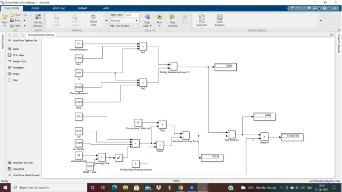
- From the above we can model we can observe the calculation of different forces of aircraft & towing vehicle and power required by the towing vehicle.
- Firstly constant blocks are used to fed the parameters such as mass, coefficient and the required paramters to calculate the forces.
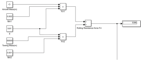
- The Rolling resistance forces of Aircraft and Towing vehicle are calculated and found to be 5396 N
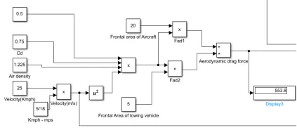
- The Aero dynamic drag forces of aircraft and towing vehicle are calculated and from display it is found to be 553.8 N
- The total forces is calculated by summing up all the forces above. The total force is 5949 N
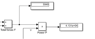
- Then power required is calculated by multiplying the total force & velocity P = F* V and the power is 41.3KW.
- The power required is which is equal to the above value which occured by manual caluculation.
7.
A. Design an electric powertrain with type of motor, it’s power rating, and energy requirement to fulfill aircraft towing application in Simulink. Estimate the duty cycle range to control the aircraft speed from zero to highest. Make all required assumptions. Prepare a table of assumed parameters. Draw a block diagram of powertrain.
Let the assumption be according to the above challenge.
Assumptions
Mass of aircraft = 250,000kg
Mass of Towing Vehicle= 50,000kg
Total mass (m)= 50,000+250,000 =300,000kg
Frontal Area of the aircraft (A1) =20 m^2
Frontal Area of the Towing vehicle (A2) =5 m^2
Coefficient of rolling resistance of aircraft rr1 = 0.002
Coefficient of rolling resistance of towing vehicle rr2 = 0.001
Drag coefficient (Cd) =0.75
Air density = 1.225Kg/m3
Speed of the vehicle (V) =25Kmph
converting it into m/sec
V = 25*5/18 =6.9445m/sec
The total force obtained to be 5949.35 N and the power required for the towing vehicle is obatined to 42 KW.
The torque required for the vehicle is
Torque T = Total force (F) * radius of tyre(r) / Gear Ratio(G).
Let radius of tyre = 15 inches = 0.4 m
Gear ratio = 8
By substituting
T = 5949.35 * 0.4/ 8
= 297.5 Nm
Energy required from the battery is obtained by assuming the time of towing is 5 min i.e., 300 sec
Energy E = Power * Time of towing
E = 42 * 300 = 12600 KJ
With the above power and torque rating the motor considered with Motor specifications are

Full load Efficiency-94.5%
Full load current - 150A
Full load Torque – 300 Nm
Rated voltage – 400V/50 Hz
Duty cycle to control the speed is
D = Power output Po / Power Input Pi
Po = Power req = 42 KW
Pi = rated voltage * current = 400 * 150 = 60KW
Duty cycle D = 42 / 60
D = 0.7
D = 70%
Simulink model
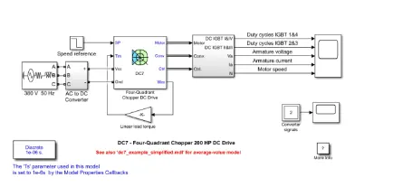
- Before starting the simulation, set the initial bus voltage to 515 V via the GUI block
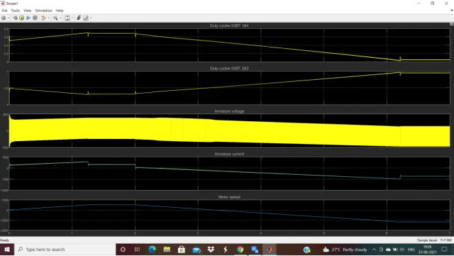
- Start the simulation. You can observe the motor armature voltage and current, the four IGBT pulses and the motor speed on the scope. The current and speed references are also shown.
- The motor is coupled to a linear load, which means that the mechanical torque of the load is proportional to the speed.
- The speed reference is set at 500 rpm at t = 0 s. Observe that the motor speed follows the reference ramp accurately (+400 rpm/s) and reaches steady state around t = 1.3 s.
- The armature current follows the current reference very well, with fast response time and small ripples. Notice that the current ripple frequency is 5 kHz.
- At t = 2 s, speed reference drops to -1184 rpm. The current reference decreases to reduce the electromagnetic torque and causes the motor to decelerate with the help of the load torque.
- At t = 2.2 s, the current reverses in order to produce a braking electromagnetic torque (dynamic braking mode). This causes the DC bus voltage to increase.
- At t = 3.25 s, the motor reaches 0 rpm and the load torque reverses and becomes negative. The negative current now produces an accelerating electromagnetic torque to allow the motor to follow the negative speed ramp (-400 rpm/s). At t = 6.3 s, the speed reaches -1184 rpm and stabilizes around its reference.
Block diagram of Powertrain
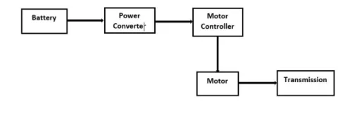
Table of assumed parameters
|
S.No. |
Parameter |
Value |
||
|
1 |
Mass of Aircraft |
250000 kg |
||
|
2 |
Mass of towing vehicle |
50000 kg |
||
|
3 |
Total Mass |
300000 kg |
||
|
4 |
aircraft coeff of rolling resistance |
0.002 |
||
|
5 |
vehicle coeff of Rolling resistance |
0.001 |
||
|
6 |
Frontal Area of the aircraft |
20 m^2 |
||
|
7 |
Frontal Area of towing vehicle |
5 m^2 |
||
|
8 |
Air density |
1.225 kg/m3 |
||
|
9 |
Drag Coefficient |
0.75 |
||
|
10 |
Speed of the vehicle(Kmph) |
25 Kmph |
||
|
11 |
Speed of the vehicle(m/s) |
6.9445 m/s |
||
|
12 |
Tyre radius |
15 inch |
||
|
13 |
Gear Ratio |
8 |
||
|
14 |
Towing Time |
300 sec |
||
|
|
|
|||
|
S.No. |
Motor Specifications |
|||
|
1 |
Rated voltage |
400 V |
||
|
2 |
Power |
60 KW |
||
|
3 |
Full load torque |
300 Nm |
||
|
4 |
Full load current |
150 A |
||
|
5 |
Motor Efficiency |
94.50% |
||
B. Excel sheet of Parameters
https://in.docworkspace.com/d/sIDDT3PQt4fPMhgY
The link of excel sheet with parameters is provided.