Project-1: Powertrain for aircraft in runways
PART A
1. Search and list out the total weight of various types of aircrafts.
Ans:
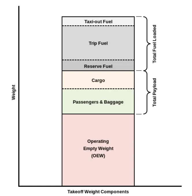
The aircraft gross weight (also known as the all-up weight and abbreviated AUW) is the total aircraft weight at any moment during the flight or ground operation.
An aircraft's gross weight will decrease during a flight due to fuel and oil consumption. An aircraft's gross weight may also vary during a flight due to payload dropping or in-flight refuelling.
At the moment of releasing its brakes, the gross weight of an aircraft is equal to its takeoff weight. During flight, an aircraft's gross weight is referred to as the en-route weight or in-flight weight.
The following image depicts takeoff weight components.
MTOW-Maximum Take off weight
MLW-Maximum Landing Weight
|
Type |
MTOW [kg] |
MLW [tons] |
|
Antonov An-225 |
640,000 |
591.7 |
|
Scaled Composites Model 351 Stratolaunch |
589,670 |
|
|
Airbus A380-800[1][2] |
575,000 |
394 |
|
Boeing 747-8F |
447,700 |
346.091 |
|
Boeing 747-8 |
443,613 |
306.175 |
|
Boeing 747-400ER |
412,770 |
295.742 |
|
Antonov An-124-100M |
405,060 |
330 |
|
Boeing 747-400 |
396,900 |
295.742 |
|
Lockheed C-5 Galaxy[3][4][5] |
381,000 |
288.417 |
|
Boeing 747-200[6] |
377,840 |
285.700 |
|
Boeing 747-300[6] |
377,840 |
260.320 |
|
Airbus A340-500[7] |
371,950 |
240 |
|
Airbus A340-600[7] |
367,400 |
256 |
|
Boeing 777F |
347,800 |
260.816 |
|
Boeing 777-300ER |
351,800 |
251.29 |
|
Boeing 777-200LR |
347,450 |
223.168 |
|
Boeing 747-100[6] |
340,200 |
265.300 |
|
Airbus A350-1000 |
308,000 |
233.5 |
|
Boeing 777-300 |
299,370 |
237.683 |
|
Boeing 777-200ER |
297,550 |
213.00 |
|
Airbus A340-300[7][8] |
276,700 |
190 |
|
McDonnell Douglas MD-11 |
273,300 |
185 |
|
Airbus A350-900 |
270,000 |
175 |
|
Ilyushin Il-96M |
270,000 |
195.04 |
|
McDonnell Douglas DC-10 |
256,280 |
183 |
|
Boeing 787-9[9] |
254,000 |
192.777 |
|
Boeing 787-10[9] |
254,000 |
201.849 |
|
Airbus A340-200[7][10] |
253,500 |
181 |
|
Ilyushin IL-96-300 |
250,000 |
175 |
|
Airbus A330-300[11][12] |
242,000 |
185 |
|
Airbus A330-200[11][12] |
242,000 |
180 |
|
Lockheed L-1011-500 |
231,300 |
166.92 |
|
Boeing 787-8[9] |
228,000 |
172.365 |
|
Lockheed L-1011-200 |
211,400 |
|
|
Ilyushin IL-86 |
208,000 |
175 |
|
Boeing 767-400ER |
204,000 |
158.758 |
|
Airbus A300-600R[13] |
192,000 |
140 |
|
Boeing 767-300ER |
187,000 |
136.08 |
|
Concorde |
185,000 |
111.1 |
|
Airbus A300-600[13] |
163,000 |
138 |
|
Boeing 767-300 |
159,000 |
136.078 |
|
Boeing 707-120B[14] |
117,000 |
86.3 |
|
Boeing 757-200 |
116,000 |
89.9 |
|
Boeing 720B[15] |
106,000 |
79.5 |
|
Boeing 720[15] |
104,000 |
79.5 |
|
Tupolev Tu-154M |
104,000 |
80 |
|
Tupolev Tu-204SM |
104,000 |
87.5 |
|
Convair 880 |
87,500 |
|
|
Boeing 737-900 |
85,000 |
66.36 |
|
Boeing 737-900ER |
85,000 |
71.35 |
|
Boeing 727-200 Advanced[16] |
84,000 |
70.1 |
|
Airbus A321-100[17] |
83,000 |
77.8 |
|
Boeing 737-800 |
79,000 |
65.32 |
|
Boeing 727-200[16] |
78,000 |
68.1 |
|
McDonnell-Douglas MD-83 |
73,000 |
63.28 |
|
Boeing 727-100[16] |
72,500 |
62.4 |
|
Boeing 727-100C[16] |
72,500 |
62.4 |
|
McDonnell-Douglas MD-90-30 |
71,000 |
64.41 |
|
de Havilland Comet 4 |
70,700 |
|
|
Boeing 737-700 |
70,000 |
58.06 |
|
Airbus A320-100[17] |
68,000 |
66 |
|
Boeing 737-400 |
68,000 |
54.9 |
|
de Havilland Comet 3 |
68,000 |
|
|
Boeing 377 |
67,000 |
|
|
Boeing 737-600 |
66,000 |
54.66 |
|
Airbus A220-300 |
65,000 |
57.61 |
|
Hawker Siddeley Trident 2E |
65,000 |
|
|
Airbus A319[17] |
64,000 |
62.5 |
|
Boeing 737-300 |
63,000 |
51.7 |
|
Boeing 737-500 |
60,000 |
49.9 |
|
Airbus A220-100 |
59,000 |
50.80 |
|
Airbus A318[17] |
59,000 |
57.5 |
|
Boeing 717-200HGW |
55,000 |
47.174 |
|
Douglas DC-7 |
55,000 |
|
|
de Havilland Comet 2 |
54,000 |
|
|
Boeing 717-200BGW |
50,000 |
46.265 |
|
Embraer 175[19] |
37,500 |
32.8 |
|
Bombardier CRJ900[20] |
36,500 |
33.345 |
|
Embraer 170[21] |
36,000 |
32.8 |
|
Bombardier CRJ700 |
33,000 |
30.39 |
|
Douglas DC-4 |
33,000 |
|
|
Vickers Viscount 800 |
30,400 |
|
|
Bombardier Q400 |
28,000 |
28.01 |
Maximum Taxi Weight (MTW):
The maximum taxi weight (MTW) (also known as the Maximum Ramp Weight (MRW) is the maximum weight authorized for maneuvering (taxiing or towing) an aircraft on the ground as limited by aircraft strength and airworthiness requirements. It includes the weight of taxi and run-up fuel for the engines and the APU (Auxillary Power Unit).
It is greater than the maximum takeoff weight due to the fuel that will be burned during the taxi and runup operations.
The difference between the maximum taxi/ramp weight and the maximum take-off weight (maximum taxi fuel allowance) depends on the size of the aircraft, the number of engines, APU operation, and engines/APU fuel consumption, and is typically assumed for 10 to 15 minutes allowance of taxi and run-up operations.
Maximum Takeoff Weight (MTOW):
The maximum takeoff weight (also known as the maximum brake-release weight) is the maximum weight authorised at brake release for takeoff, or at the start of the takeoff roll.
The maximum takeoff weight is always less than the maximum taxi/ramp weight to allow for fuel burned during taxi by the engines and the APU.
In operation, the maximum weight for takeoff may be limited to values less than the maximum takeoff weight due to aircraft performance, environmental conditions, airfield characteristics (takeoff field length, altitude), maximum tire speed and brake energy, obstacle clearances, and/or en route and landing weight requirements.
Maximum Landing Weight (MLW):
The maximum weight authorised for normal landing of an aircraft.The MLW must not exceed the MTOW.
The operation landing weight may be limited to a weight lower than the Maximum Landing Weight by the most restrictive of the following requirements:
- Aircraft performance requirements for a given altitude and temperature:landing field length requirements,approach and landing climb requirements
- Noise requirements
If the flight has been of short duration, fuel may have to be jettisoned to reduce the landing weight.
Overweight landings require a structural inspection or evaluation of the touch-down loads before the next aircraft operation.
Maximum Zero Fuel Weight (MZFW):
The maximum permissible weight of the aircraft less all usable fuel and other specified usable agents (engine injection fluid, and other consumable propulsion agents). It is the maximum weight permitted before usable fuel and other specified usable fluids are loaded in specified sections of the airplane.
------------------------------x------------------------------------x------------------------------------------
2. Is there any difference between ground speed and air speed?
Ans:
Air speed vs Ground speed:
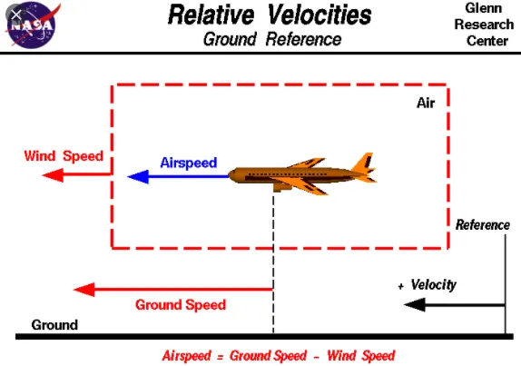
As mentioned above, true airspeed is simply the speed at which an aircraft is moving relative to the air it is flying in. As such, it’s also the speed at which the air is flowing around the aircraft’s wings.
Ground speed, on the other hand, is the aircraft’s speed relative to the ground. One thing that should be noted here is that it’s its horizontal rather than vertical speed – an aircraft climbing completely vertically would have a ground speed of zero.
In other words, while airspeed is what determines whether there is enough airflow around an aircraft to make it fly, ground speed is what determines how fast an aircraft will get to its destination.
Wind's effect on Ground speed:
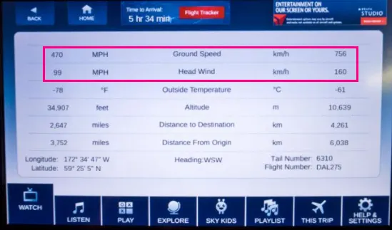
The relationship between airspeed and ground speed is fairly simple. Ground speed is simply the sum of airspeed and wind speed.
If the aircraft is flying in the same direction as the wind is blowing, the aircraft experiences tailwind, and its ground speed is higher than its airspeed. On the other hand, if the wind is blowing against the direction the aircraft is traveling in, the aircraft experiences headwind, and its ground speed is lower than its airspeed.
To give you an actual example, imagine an aircraft that cruises at an airspeed of 500 miles per hour that has to cover a ground distance of 2,000 miles.
If there is no wind at all, then both the aircraft’s airspeed and ground speed would be the same 500 miles per hour, and the aircraft would reach its destination in four hours.
If there was a 100 miles per hour headwind – wind blowing against the aircraft’s direction of travel – the aircraft would still be traveling at an airspeed of 500 miles per hour. However, its ground speed would be just 400 miles per hour (100 miles per hour slower than its airspeed). And as such, it would take the aircraft five hours to reach its destinations.
Finally, if there was a 100 miles per hour tailwind – wind blowing in the same direction as the aircraft’s travel – the aircraft would still be traveling at an airspeed of 500 miles per hour, but its ground speed would be 100 miles faster. And, at 600 miles an hour, the aircraft would reach its destination in just three hours and twenty minutes.
The above is the reason why some flights go “out of their way” to avoid headwinds or catch tailwinds. And, why some flights might appear to be traveling at “supersonic speeds,” even though their airspeed – the speed that would actually matter in determining whether or not the flight truly is supersonic – is subsonic.
-------------------------------x----------------------------------------------x----------------------------------
3. Why is it not recommended to use aircraft engine power to move it on the ground at Airport?
Ans:
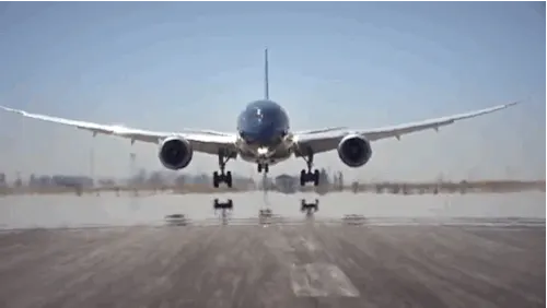
Description:
- The term Aircraft Ground Running is usually used to describe the operation of some or all of the engines of an aircraft, whilst on the ground, for the purpose of functionally checking the operation of either engines or aircraft systems.
- This usually takes place prior to the Release to Service of an aircraft from maintenance. Ground running may be carried out either prior to, during or after the rectification of a defect or scheduled work on an engine or an aircraft system, when this requires engines to be operating in order to assess its function.
- Although the aircraft may need to be taxied or towed to an approved ground running position under a clearance from ATC, most operators and maintenance organisations do not require pilots to be on board because aircraft technicians can be trained and approved for these duties.
The Risk to Operational safety:
The risks which may arise from engine ground running relate to the potential for loss of control of the aircraft by those persons occupying the pilot seats in the flight deck. In most cases, such persons will be maintenance personnel holding specific company-issued approval for the required tasks. The consequences of loss of control during taxi or towing are the same as apply to these operations generally and this article is concerned only with the risks arising from the static running of one or more aircraft engines.
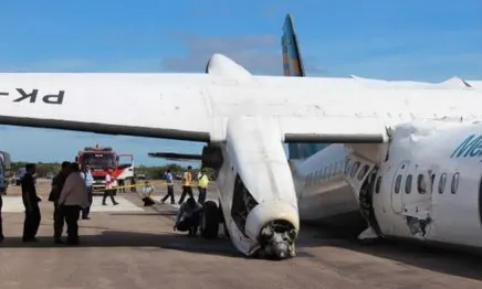
Unwanted consequences from such static running are mainly related to those arising from the unintended movement of the aircraft during engine running - effectively a loss of control - especially during high power engine running. Damage can occur to the aircraft itself, other aircraft nearby or to airside structures. In addition, there is a risk of injury to ground support personnel who may be in relatively close proximity to the aircraft.
Task details - Key Risks Control:
- Thrust levels above ground idle should be applied symmetrically. Task Checklists must be constructed so that there is never a cause to temporarily defer items and continue. Once a task has been initially briefed by the person authorised to supervise it, modifications to the briefed task should only be permitted within a clearly defined limit without a complete task re-briefing.
- Where two persons, both holding the necessary authorisation to be able to supervise a task, are teamed together to conduct it, one of them must be designated by the Aircraft Operator or MRO as the supervisor for a particular task and should lead the pre-task briefing. No change of designated supervisor should occur during a briefed task.
- Any plan for engine ground running which is authorised for power above Ground Idle must be carried out with the aircraft in a position in which unexpected and unintended forward movement will not result in damage or injury should the appropriate response from the designated supervisor be delayed.
- Knowledge of the brake and hydraulic systems on any aircraft type for which a person is permitted to occupy a flight deck seat, for the purposes of engine ground running, must be comprehensive and formally certified as such. All equipment and personnel must be completely clear of an aircraft before engine running above ground idle occurs.
- Where local regulations require that contact with ATC GND is maintained in connection with ground running, this should specifically include ensuring that ATC are advised prior to commencing or after completing any periods of ground running at power above ground idle, even if such activity does not require explicit ATC permission at the site being used.
- Where engines are being run for the purposes of facilitating system tests, a specific test sequence should be pre-specified in text form and should incorporate any appropriate checklists or give specific AMM references to these.
- If the latter method is used, current copies of such checklists should be appended to the test sequence. Wheel chocks should be in place at the main landing gear for all ground running. In the case of ground running of engines above ground idle, care should be given to checking that the chocks being used are of a type which corresponds to the mass of the aircraft involved and that the chocking of wheels other than those at the main landing gear assemblies is considered.
- AMM’s require that a fire extinguisher be within the vicinity of the engine, particularly if the engine cowlings are open and you are going to do leak check. This is because, in the case of a fire due to an oil/fuel leak in the fan section, the engine fire extinguishers may not be not be effective and you have to fight the fire with an external fire extinguisher.
-------------------------------------x------------------------------------------x---------------------------------
4. How an aircraft is pushed to runway when its ready to take off?
Ans:
Ready for take-off in ten steps…
- The pilot parks the aircraft in exactly the right place. Usually with the help of an automatic system, but occasionally guided by a marshaller waving two paddles or wands. Dozens of handling personnel are already standing by to perform a whole range of tasks simultaneously.
- As soon as the aircraft is stationary and the engines are switched off, the first priority is to disembark the passengers as quickly as possible. The apron handler places chocks in front of the wheels and connects the ground power. Meanwhile, the passenger bridge manoeuvres up to the door and a belt loader rolls up to the cargo hold. Luggage is unloaded and transferred to the terminal on baggage carts.
- Refuelling begins, usually from a hydrant at the stand. A hose is attached to this from a special vehicle called a dispenser, with the other side connected to the fuel tank in the wing. Read more about refuelling here.
- Now it is time to service the aircraft. The caterer loads new meals and takes away the food waste and used cutlery and crockery. Other activities include draining the lavatories, replacing the headrest covers, removing rubbish and distributing fresh blankets and in-flight magazine.
- A specialist team – or sometimes the crew themselves – cleans the cabin so that the new passengers board a pristine aircraft.
- Meanwhile, specialists from the airline conduct a technical check to make sure that the engines, wings, control surfaces, landing gear, instruments, doors and other equipment are in full working order.
- The aircraft is now ready for baggage to be loaded for the next flight. This is a quick process, on average taking only 10-15 minutes. A little later the passengers start boarding. As soon as they are all in their seats, the door is closed and the pilot informs air-traffic control that the flight is ready for departure.
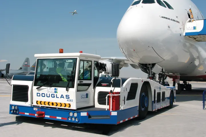
- The apron handler removes the chocks. A so-called pushback truck reverses the aircraft into taxiing position, pushing it with a towbar attached to the nose-wheel strut. Or, in the most modern versions, by actually lifting the wheel. That speeds up coupling and decoupling.
- The aircraft taxis to the runway to depart at the agreed time.
- The pilot waits for permission to take off from air-traffic control. This is possible once the departure route is clear. As soon as the go-ahead is received, the plane takes to the air at full power.
Taxiing in aircraft:
Taxiing (rarely spelled taxying) is the movement of an aircraft on the ground, under its own power, in contrast to towing or pushback where the aircraft is moved by a tug. The aircraft usually moves on wheels, but the term also includes aircraft with skis or floats (for water-based travel).
An airplane uses taxiways to taxi from one place on an airport to another; for example, when moving from a hangar to the runway. The term "taxiing" is not used for the accelerating run along a runway prior to takeoff, or the decelerating run immediately after landing, which are called the takeoff roll and landing rollout, respectively.
-------------------------------------x-----------------------------------------x----------------------------------
5. Learn about take off power, tyre design, rolling resistance, tyre pressure, brake forces when landing.
Ans:
(i) Take off Power:
For light aircraft, usually full power is used during takeoff. Large transport category (airliner) aircraft may use a reduced power for takeoff, where less than full power is applied in order to prolong engine life, reduce maintenance costs and reduce noise emissions. In some emergency cases, the power used can then be increased to increase the aircraft's performance. Before takeoff, the engines, particularly piston engines, are routinely run up at high power to check for engine-related problems. The aircraft is permitted to accelerate to rotation speed (often referred to as Vr).
The term rotation is used because the aircraft pivots around the axis of its main landing gear while still on the ground, usually because of gentle manipulation of the flight controls to make or facilitate this change in aircraft attitude (once proper air displacement occurs under / over the wings, an aircraft will lift off on its own; controls are to ease that in).
On take-off, in order to position the aircraft to a safe height away from terrain and obstacles (i.e. a flight path of maximum height and minimum ground distance desired), the engine thrust is set to a high ‘take-off power’ setting (although this is not necessarily full power) and the aircraft attitude is pitched up to maintain a specific speed (usually in the region of V2 + 15kts). Once the ‘safe height’ is reached the engine thrust can therefore be reduced to a more appropriate (i.e. efficient) setting and the aircraft flight path can be changed to a more appropriate (i.e. efficient) flight path.
(ii) Tyre Design:
Designing aircraft tires is a very intense undertaking. Once an aircraft manufacturer goes to the tire manufacturer with the size and weight requirements, the tire manufacturer begins the process of designing a tire that meets the needs of the aircraft manufacturer as well as all regulatory requirements — including foreign regulations in many cases.
Engineers are challenged with designing tires with cool running, heat-resistant materials while simultaneously exceeding tire service requirements. Tire prototypes are put through rigorous tests that simulate cycles of landings, take-offs, and taxi operations. It is only after the tires pass all mandatory tests and meet the requirements of the aircraft manufacturer and airworthiness authorities that the tires are put into production.
Two types of tires are used in aircraft applications — bias-ply tires and radial tires. Although both types of tires share some similarities in design, there are differences that need to be noted.
Bias-ply tire construction:
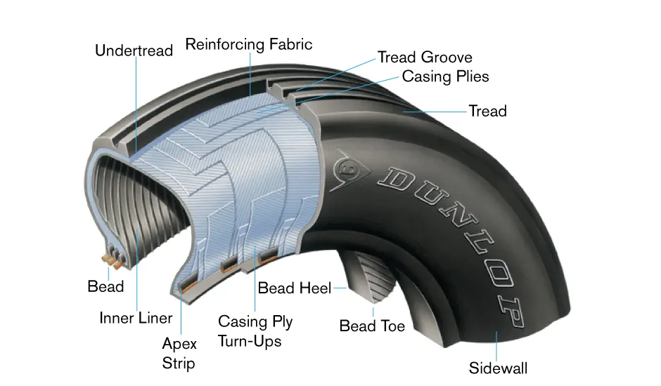
A cutaway of a typical bias-ply tire is shown in above figure. Bias-ply tires are popular choices for aircraft tires because of their durability and retreadability. The tire construction consists of the following components:
Tread: The tread is made of rubber mixed with other additives to obtain the desired level of toughness, durability, and resistance to wear. The tread pattern is designed to aircraft operational requirements, with the ribbed tread design used widely due to its good traction under varying runway conditions.
Sidewall: The sidewall is a protective layer of rubber that covers the outer casing ply. It extends from the tread edge to the bead area.
Tread Reinforcing Ply: One or more layers of fabric that strengthens and stabilizes the tread area for high-speed operation. It also serves as a reference for the buffing process when tires are retreaded.
Buff Line Cushion: The buff line cushion is made of rubber compound to enhance the adhesion between the tread reinforcing ply and the breakers or casing plies. It is of sufficient thickness to allow for the removal of the old tread when the tire is retreaded.
Breakers: Breakers are reinforcing plies of rubber-coated fabric placed under the buff line cushion to protect casing plies and strengthen and stabilize the tread area. They are considered an integral part of the casing construction.
Casing Plies: Alternate layers of rubber-coated fabric (running at opposite angles to one another) provide the strength of the tire.
Wire Beads: Hoops of high tensile strength steel wire that anchor the casing plies and provide a firm mounting surface on the wheel. The outer edge of the bead that fits against the wheel flange is called the bead heel. The inner bead edge is called the bead toe.
Apex Strip: A wedge of rubber affixed to the top of the bead bundle.
Flippers: Layers of rubberized fabric that help anchor the bead wires to the casing and improve the durability of the tire.
Ply Turnups: The casing plies are anchored by wrapping them around the wire beads, thus forming the ply turnups.
Chafer: A protective layer of rubber and/or fabric located between the casing plies and wheel to minimize chafing.
Liner: In tubeless tires, the liner is a layer of low permeability rubber that acts as a built-in tube and restricts gas from diffusing into the casing plies. In tube-type tires, a thinner liner is used to prevent tube chafing against the inside ply.
Radial tire construction:
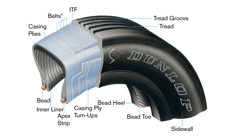
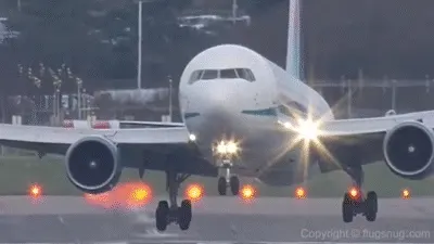
A typical radial tire is illustrated in above figure. With their rigid belt, they provide increased landings and reduced rolling resistance. They have fewer components in their construction and are lighter than similarly sized bias ply tires. Components that differ from bias-ply construction as follows:
Overlay: A layer of reinforcing rubber coated fabric placed on top of the belts to aid in high speed operation.
Belt Plies: A composite structure that stiffens the tread area for increased landings. The belt plies increase the tire strength in the tread area.
Casing Plies: As in bias-ply tires, the casing plies are layers of rubber-coated fabric. However, unlike those in bias plies that run at opposite angles to one another, radial plies run radially from bead to bead.
Chippers: The chippers are layers of rubber-coated fabric applied at diagonal angles that improve the durability of the tire in the bead area.
Tire Inspection:
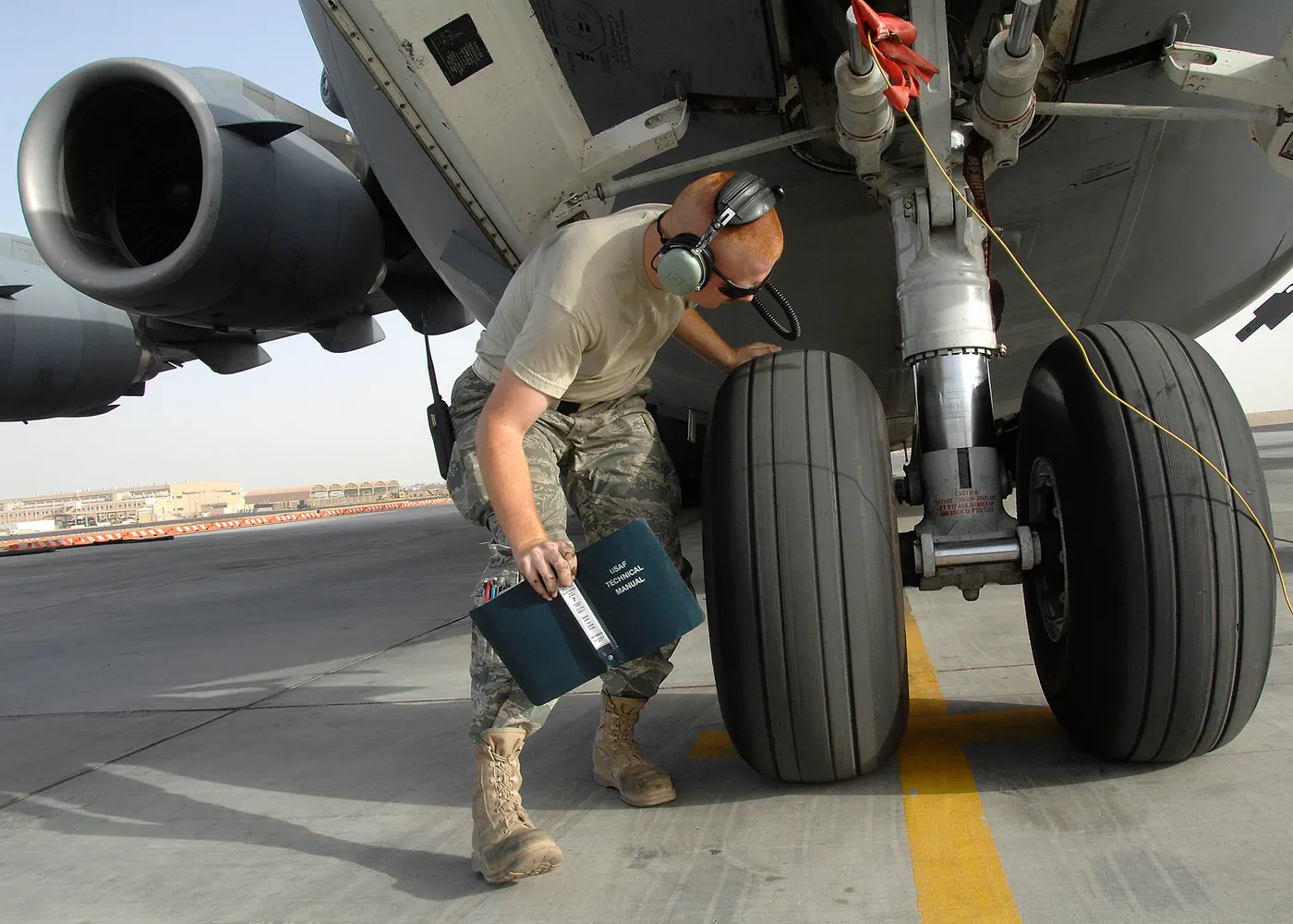
In order to ensure safety and increase tire life, systematic inspections of mounted tires should be performed. A word of warning — Never probe cracks, cuts, or embedded foreign objects while the tire is inflated! Serious injuries could result. In addition, defects such as cuts, cracks, and bulges should be marked with a crayon or chalk prior to deflation since the defects may disappear when the tire is deflated. The following should be checked:
Tread wear: Treads should be visually inspected for wear. The tire should be replaced when tread has worn to the base of any groove at any spot or to a minimum depth specified in the aircraft maintenance manual. Tread wear can also be an indication of improper tire inflation. Refer to Figure 3 for tread wear indications.
Tread cuts: The tire should be inspected for cuts and other foreign damage. Follow the criteria from the applicable aircraft maintenance manual. If no specific criteria is outlined in the manual, the following can be used for guidance in determining tread cuts.
(iii) Rolling resistance:
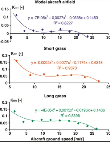
When you press down on the accelerator in your vehicle, you are essentially transferring energy—in the form of gas or electricity, depending on your automobile, through the engine and other systems in your vehicle. That results in your tires turning and enough momentum being built up to move your automobile. To accomplish this, though, your vehicle must overcome a lot of different factors that can make it resistant to forward movement. One of those factors is the tires’ rolling resistance.
Tire rolling resistance is the energy that your vehicle needs to send to your tires to maintain movement at a consistent speed over a surface. In other words, it is the effort required to keep a tire rolling. The main contributor to rolling resistance is the process known as hysteresis. Hysteresis is essentially the energy loss that occurs as a tire rolls through its footprint. The energy loss must be overcome by the vehicle’s engine, which results in wasted fuel.
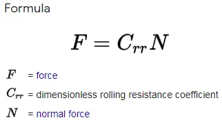
Benefits of low rolling resistance:
For drivers who are interested in optimizing their vehicle’s fuel efficiency, the answer is yes. Low rolling resistance tires can be much more fuel-efficient tire than conventional tires. The U.S. Department of Energy has done research that shows that utilizing low rolling resistance tires can have as much as a 10% fuel savings impact for drivers. However, for most drivers, the fuel savings is around 3%. Although that doesn’t sound like a lot, those numbers can add up over time and result in a substantial savings in fuel spending and waste.
Are there compromises with low rolling resistance tire:
Like most things in life, you can’t get something without giving a little, and the same holds true for low rolling resistance tires, unless new technology is introduced. For example, a tire manufacturer can reduce tread depth to improve rolling resistance. However, there will be a corresponding reduction in tire wear life. To overcome this tradeoff, new technology could be designed to maintain the wear performance, while still improving rolling resistance.
(iv) Tyre Pressure:
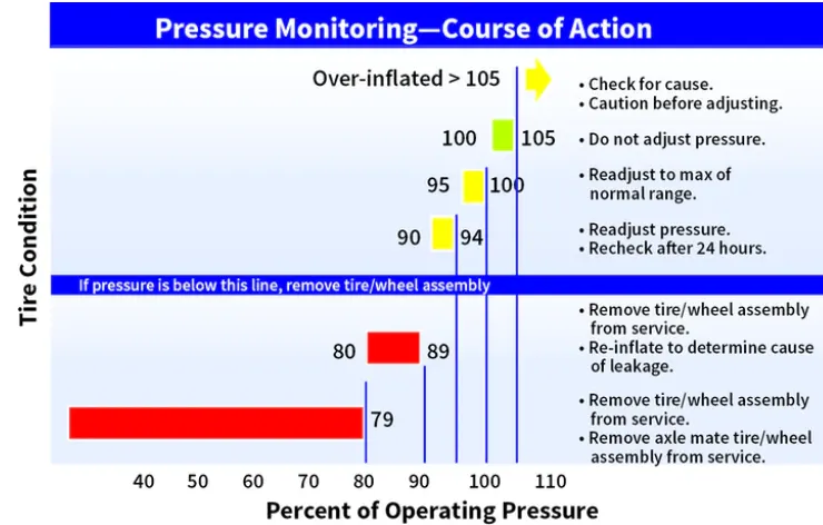
Aircraft tires are not the same as passenger car or truck tires. As a result, their care and service requirements differ. Note that although the tires are dimensionally similar, they differ significantly in rated inflation pressure, load, and speed. Additionally, the passenger car and truck tires are able to operate continuously because they reach thermal equilibrium while aircraft tires do not.
An aircraft tire which taxis continuously at rated load and 40 mph will continue to heat up until the tire fails. The failure to reach thermal equilibrium is a consequence of the high deflections (the difference between the unloaded and loaded tire section height) at which aircraft tires operate. High inflation pressure and high deflection rates – 2.5 times greater than a car tire – allow relatively small tires to support the high loads of an aircraft.
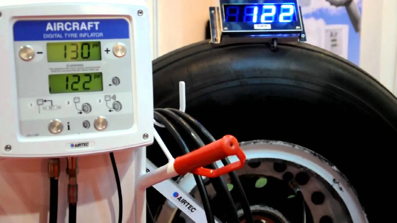
Because aircraft tires operate at such high extremes of pressure, load, and speed, their care and service is critically important. The most important action an operator can take to prevent tire-related events is to maintain proper tire inflation pressure. Failure to keep aircraft tires properly inflated can lead to very serious consequences.
The most serious of these is the structural failure of the tire. If the tire operates underinflated or overdeflected/overloaded, the nylon cords which form the structure of the tire go in and out of compression as the tire rotates. This weakens the cords – much like a paperclip which is bent back and forth – until eventually the cords break. If enough cords break, the entire structure will eventually fail. Figure 2 shows what a compressive break in an interior ply looks like. This particular break damaged the inner liner, allowing air to migrate through the tire to the atmosphere.
In order to ensure that an aircraft’s tires are properly inflated, Michelin recommends checking the inflation pressure, with a calibrated gauge, before the first flight of the day or before each flight if not flown daily.
Why is it important to check the pressure every day? Because of the high pressures and extreme temperatures at which aircraft tires operate, they do not hold air perfectly. In fact, an aircraft tire can lose up to 5 percent of its pressure in 24 hours and still be perfectly serviceable.
(v) Brake force:
Bringing at aircraft down to the runway from 37,000 feet is only part of the challenge. It’s not over until the aircraft is safely parked at its gate. In order to do this, pilots have a number of systems available to slow the aircraft down, even in a blizzard on a snow-covered runway.
The 787 braking system:
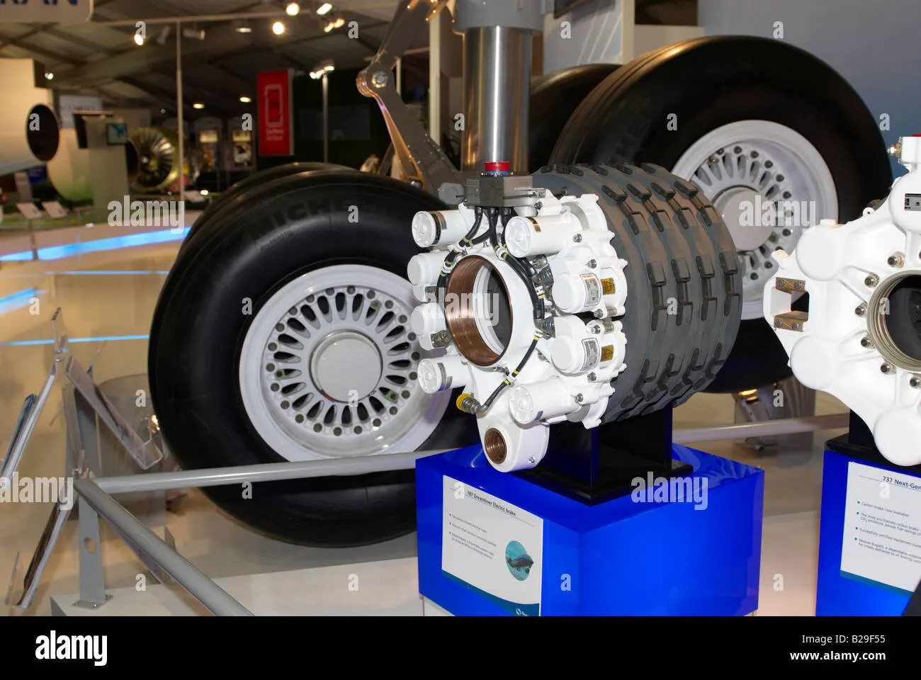
Stopping a 200-tonne aircraft landing at 180 mph requires a lot of braking force. To do this, the 787 has one brake unit on each of the eight wheels on the main gear assembly. On other aircraft types, the brake units are powered by the hydraulics system. An electrical signal is sent from the flight deck to hydraulic actuators near the main landing gear. Here, hydraulic fluid at 3,000 pound per square inch is used to force the brake unit against the wheel, thus slowing it down.
This system works fine, but the pipes and actuators that form this part of the hydraulic system come at a considerable weight cost. Extra weight means more fuel burn, which in turn increases costs and carbon emissions.
Electric brakes:
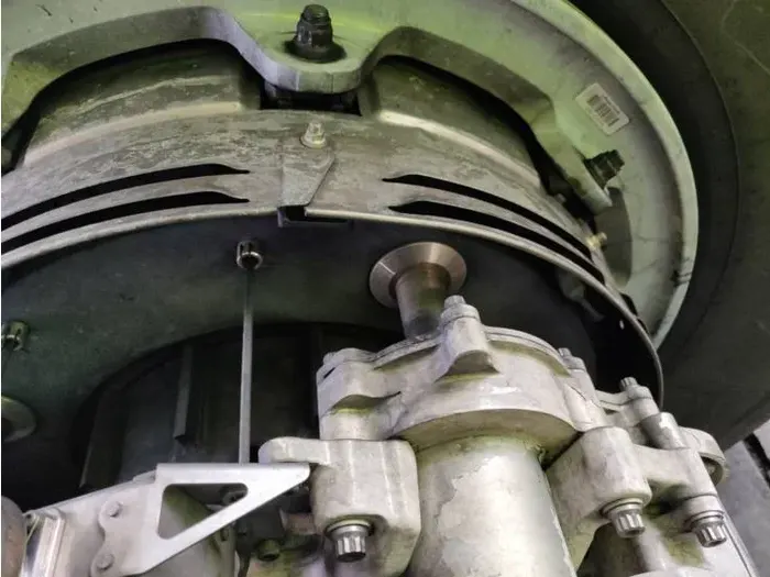
The brake system on the 787 Dreamliner is controlled by the pilots pressing the tops of the rudder pedals under their feet, demanding the rate of braking which they require. This sends an electronic signal to the Left and Right Brake System Control Units (BSCUs).
These then send signals to the four Electronic Brake Actuator Controllers (EBAC) which control the rate of braking on the wheels. Each wheel has four Electric Brake Actuators (EBA), a kind of piston which presses against the carbon brake discs.
Auto brake:
Pressing on the brakes is pretty straight forward when taxiing in a straight line at low speed. However, when we’re landing in strong winds, it can be a little tricky. We need to use our feet on the rudder pedals to line the nose of the aircraft up with the runway centerline at the last moment. Then, whilst holding that position, slide our feet up to press the toe brakes. Really not very easy when moving at 160 mph.
To help us get the braking underway as soon as we touch down, we have the autobrake system.This provides automatic braking at a preselected rate as soon as the aircraft senses that it is on the ground. It also provides full braking pressure in the case of a rejected takeoff if the speed is above 85 knots (98 mph).
------------------------------------x---------------------------------------------x------------------------------
PART - B
6. A. With necessary assumptions, calculate the force and power required to push / pull an aircraft by a towing vehicle.
B. Develop the model for the calculated force and power using Simulink.
Ans:
Assumptions for towing vehicle:
Kerb weight = 35000 Kg
Payload = 120000 Kg
Total mass of vehicle = 35000 + 120000 = 155000 Kg
Coefficient of rolling resistance (μrr) = 0.012
Drag coefficient (Cd) = 0.6
Frontal area (A) = 15 m²
Velocity (V) = 15 kmph or 4.16 m/s
Air density (ρ) = 1.33
(i) Rolling resistance force (Frr)
It is one of the forces that act to oppose the motion of a driver.
Frr = μrr * m * g
where, μrr is coefficient of rolling resistance
m is the mass of the towing vehicle
g is the gravity
Frr = 0.012 * 155000 * 9.81
Frr = 18246.6 N
(ii) Air drag coefficient force (Fad)
The drag coefficient of an object in a moving fluid influence drag force.
Fad = (1/2)*ρ*Cd*A*V²
where, ρ is the air density
Cd is the drag coefficient
A is the Frontal area m²
V is the avg velocity in m/s
Fad = (1/2)*1.33*0.6*15*4.16²
Fad = 103.57 N
(iii) Hill climbing force (Fhc):
Fhc = m * g * sinθ
where, m is the mass in kg
g is the gravity
θ is the angle of up grade
Here we are not taken any upgradient hence the value of angle was 0, therefore Fhc was 0N
Total tractive force (Fte) = Frr + Fad + Fhc
Fte = 18246.6 + 103.57 + 0
Fte = 18350.17 N
Power required by the vehicle
P = Fte * V
where
Fte is total tractive force
V is the velocity in m/s
P = 18350.17 * 4.16
P = 76336.7 watts or 76.33 Kw
--------------------------------x------------------------------------------x------------------------------------
Ans 6 B:
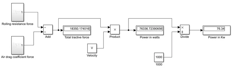
Simulink model for above calculation:
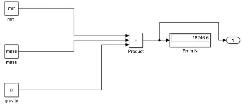
Rolling resistance force:
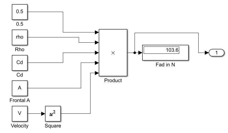
Air drag force:
- In this first we write constant values of mass, air density, Cd, frontal area, gravity and velocity in workspace command of matlab.
- Then we build a simulink model using add, product and display blocks.
Add:

The Sum block performs addition or subtraction on its inputs. The Add, Subtract, Sum of Elements, and Sum blocks are identical blocks. This block can add or subtract scalar, vector, or matrix inputs. It can also collapse the elements of a signal and perform a summation.
Product:

If there is only one input port and the Multiplication parameter is set to Element-wise(.*), a single * or / collapses the input signal using the specified operation.
Divide:

If there is only one input port and the Multiplication parameter is set to Element-wise(.*), a single * or / collapses the input signal using the specified operation.
Display:
Display input values. If the incoming signal is of type string, the 'Numeric display format' parameter selection does not affect the display of the string.
Workspace:
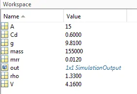
The Workspace browser enables you to view and interactively manage the contents of the workspace in MATLAB. For each variable or object in the workspace, the Workspace browser also can display statistics, when relevant, such as the minimum, maximum, and mean.
You can edit the contents of scalar (1-by-1) variables directly in the Workspace browser. Right-click the variable and select edit value. To edit other variables, double-click the variable name in the Workspace browser to open it in the Variables editor.
Output of the model:
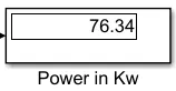
- First we assume the initial values of mass, air density, Cd, velocity, gravity of towing vehicle.
- Then we calculated rolling resistance force and air drag force by using formula.
- After that we need to add both forces to get a total tractice force in N.
- If we want Power required by the vehicle then we need to multiply by velocity to the total tractive force of the vehicle.
-------------------------------x-------------------------------------------------x------------------------------
7. A. Design an electric powertrain with type of motor, it’s power rating, and energy requirement to fulfill aircraft towing application in Simulink. Estimate the duty cycle range to control the aircraft speed from zero to highest. Make all required assumptions. Prepare a table of assumed parameters. Draw a block diagram of powertrain.
(Hint :DC7 Block)
B. Also, Design the parameters in excel sheet.
Ans A:
Here we consider the same parameters of the towing vehicle in order to calculate the energy required:
Total mass of the vehicle = 155000 Kg
Rolling resistance force = 18246.6 N
Air drag force = 103.57 N
Total Power required to the vehicle = 76.33 Kw
Tyre radious (r) = 0.4
Torque calculation:
Torque = Fte * r
= 18350.17 * 0.4
Torque = 7340 N-m
And we also assume some more parameters to calculate energy required
Time taken (t) = 10 min.
Or t = 10/60 = 0.167 hrs.
Therefore,
Energy required (E) = P * t
where, P is Power required by the vehicle
and t is the time taken to tow the air craft to the runway
E = 76.33 * 0.167
E = 12.72 Kwh
Therefore the energy required to tow the vehicle is = 12.72 KWh
For this application we consider the BLDC motor and their specifications are given below:
Input power = 90 kw
Speed (rpm) = 3000 rpm
Armature voltage = 450 V DC
Full load current = 320 A
Field voltage = 260 V DC
Field current = 5.6 A
In order to calculate the Duty cycle we must know the input and output power of the vehicle
Pin = 90 Kw
Pout = 76.33 Kw
Duty cycle = Pout/Pin
= 76.33/90
Duty cycle = 0.84 or 84 % of duty cycle
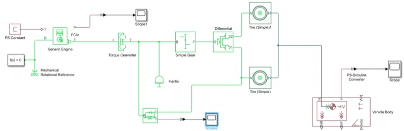
Block diagram:
Simulink model:
Results:
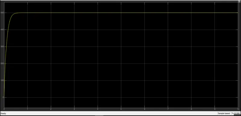
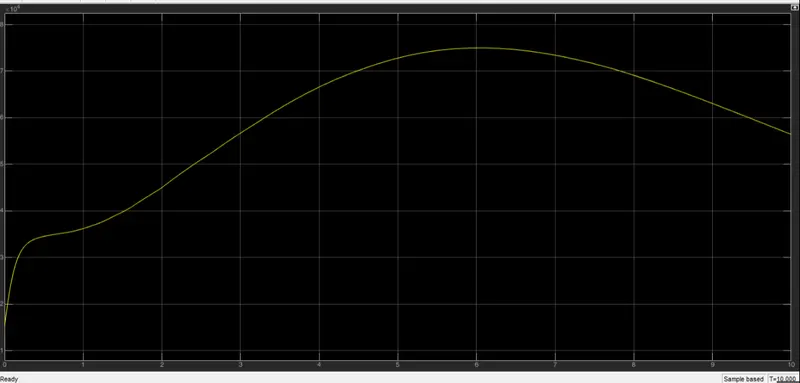
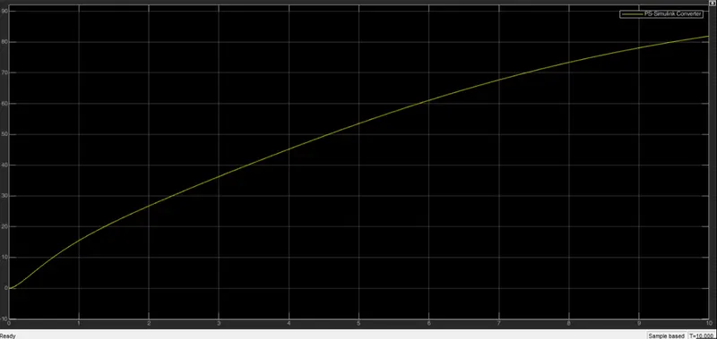
Explaination:
The first graph shows the torque representation values in that we added ideal torque sensor to sense the torque.
The second plot shows the engine power in that the towing vehicle power consumption was included.
The third plot represents velocity or speed of the towing vehicle.
-----------------------------x------------------------------------------------x-----------------------------------
Ans 7 B:
Excel sheet data for the above model:
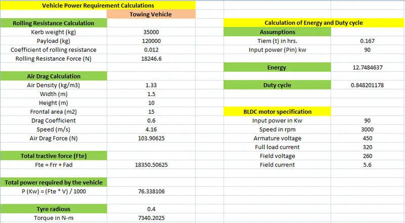
- The above excel sheet shows the calculation of rolling resistance force, air drag force, total power required by the vehicle, energy calculation and duty cycle calculation of towing vehicle.
- Each and every parameter having their own formulas to calculate.
-------------------------------x------------------------------------------------------x---------------------------