Powertrain for aircraft in runways
Target:-
- To learn about different types of aircraft mass.
- To learn about the power train of an aircraft.
Objective:-
- Search and list out the total weight of various types of aircraft.
- Is there any difference between ground speed and airspeed?
- Why is it not recommended to use aircraft engine power to move it on the ground at the Airport?
- How an aircraft is pushed to the runway when it's ready to take off?
- Learn about take-off power, tyre design, rolling resistance, tyre pressure, brake forces when landing.
- With necessary assumptions, calculate the force and power required to push/pull an aircraft by a towing vehicle.
- Design an electric powertrain with the type of motor, its power rating, and energy requirement to fulfil aircraft towing application. Estimate the duty cycle range to control the aircraft speed from zero to highest. Make all required assumptions. Prepare a table of assumed parameters. Draw a block diagram of the powertrain.
Theory:-
-
- Tell about the total weight of an aircraft we have to learn about the different types of weight associated with aviation industries and every pilot and the trained ground staff uses while talking of a successful flight.
- Basic Empty weight:- It is the weight of the aircraft with standard equipment and usable fuel and oil. And the standard equpiments includes fire extingusier, pyrotechnique.
- Dry Operating Weight:- This is also known as Aircraft prepare for service(APS), it is the basic empty weight + weight of the flight crew + their baggage and weight of the cabin crew with their luggage and passenger service equipment.
- Zero Fuel Weight:- It is the weight of the aircraft + flight crew weight and the cabin crew weight with their luggage and passenger weight and their luggage i.e, revenue and non-revenue
- Traffic Load Or PayLoad:- The weight of the passenger and their baggage is called Traffic Load Or PayLoad.
ZFW = DOW + Pay Load.
-
Maximum Ramp Weight:- It is the maximum Operating Weight with Dry operating Weight + all the Fuels.
MRW = DOW + Pay Load + TF + RF + S&T
-
Maximum Takeoff Weight:- The weight of the aircraft with anything and everything at the start of the takeoff
MToW = DOW +PL + F.O.B or TF+RF
OR
MToW = MLW+ TF
OR
MToW = MZFW + TF +RF
OR
MToW = MZFW +F.O.B
-
Regulated Takeoff Weight:- Lowest of maximum takeoff weight and performance limited takeoff weight.
Where:-
DOW = Dry Operating Weight
MRW= Maximum Ramp Weight
TF = trip Fuel
RF = Reserve Fuel
PL = Pay Load
S&T = Seafty and Taxi
MToW = Maximum Take off Weight
MLW = Maximum Landing Weight
MZFW = Maximum Zero Fuel Weight
F.O.B = Fuel On Board
- Below is the list of the commercial aircraft that are being used in the Civil Aviation Line:-
Manufacter Name Types Maximum Take off Weight (Kgs) ICCAO Designation Images AIR-BUS A380-800 A340-500 A330-900 A340-300 A330-300 A300-600R A310-300 A400M A321-1000 A220-300 A319 A318 575,000 371,950 352,000 276,700 242,000 192,000 157,000 141,000 83,000 65,000 64,000 59,000 Super Heavy Heavy Heavy Heavy Heavy Heavy Heavy Medium Medium Medium Medium 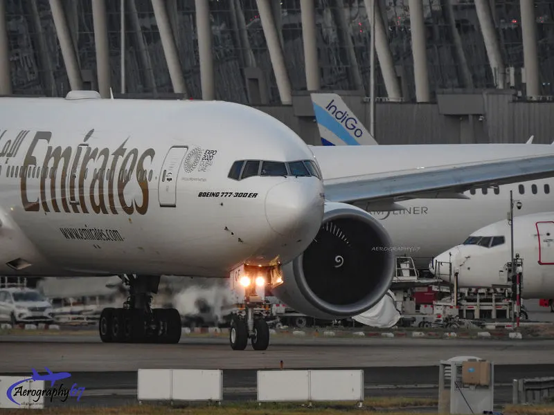
BOEING 747-8F 747-400ER 747-200 777F 747-100 777-300 787-9 767-400E 757-300 737-900 737-800 377 717-200BGW 447,700 412,770 377,840 347,800 340,200 299,370 254,000 204,600 124,000 85,000 79,000 67,000 50,000 Heavy Heavy Heavy Heavy Heavy Heavy Heavy Heavy Medium Medium Medium Medium Medium 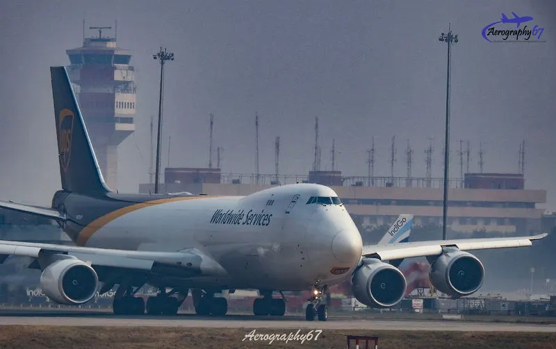
ANTONOV AN225 AN124-100M 640,000 405,060 Super Heavy 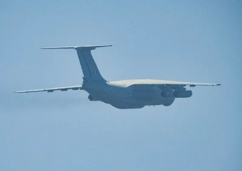
DOUGLAS MD-11 DC-10 DC-8-61 DC-8-51 MD-83 DC-7 DC-6A DC-6 DC-4 273,300 256,250 147,000 125,000 73,000 55,000 48,600 44,000 33,000 Heavy Heavy Heavy Medium Medium Medium Medium Medium Medium 
BOMBARDIER CRJ 900 CRJ 700 Q 400 CRJ 200 36,500 33,000 28,000 23,000 Medium Medium Medium Medium 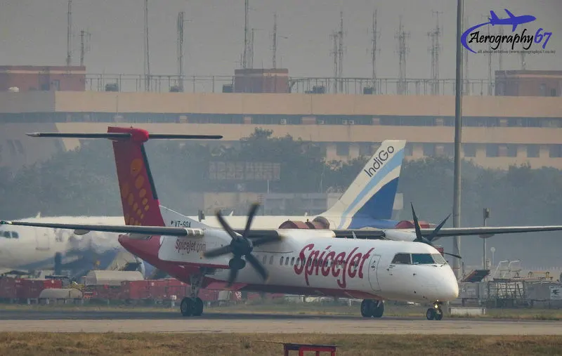
- Tell about the total weight of an aircraft we have to learn about the different types of weight associated with aviation industries and every pilot and the trained ground staff uses while talking of a successful flight.
- The difference between the Ground speed and the Airspeed is below:-
-
Ground Speed:- Ground speed is the horizontal speed of an aircraft relative to the Earth’s surface. It is vital for accurate navigation to the destination that the pilot has an estimate of the ground speed that will be achieved during a flight. The information displayed to passengers through airline aircraft's entertainment system usually gives the aircraft ground speed rather than airspeed. Ground speed can be determined by the vector sum of the aircraft's true airspeed (TAS) and the current wind speed and direction; a headwind subtracts from the ground speed, while a tailwind adds to it. Winds at other angles to the heading will have components of either headwind or tailwind as well as a crosswind component. An airspeed indicator indicates the aircraft's speed relative to the air mass. The air mass may be moving over the ground due to wind, and therefore some additional means to provide position over the ground is required. This might be through navigation using landmarks, radio-aided position location, an inertial navigation system, or GPS.
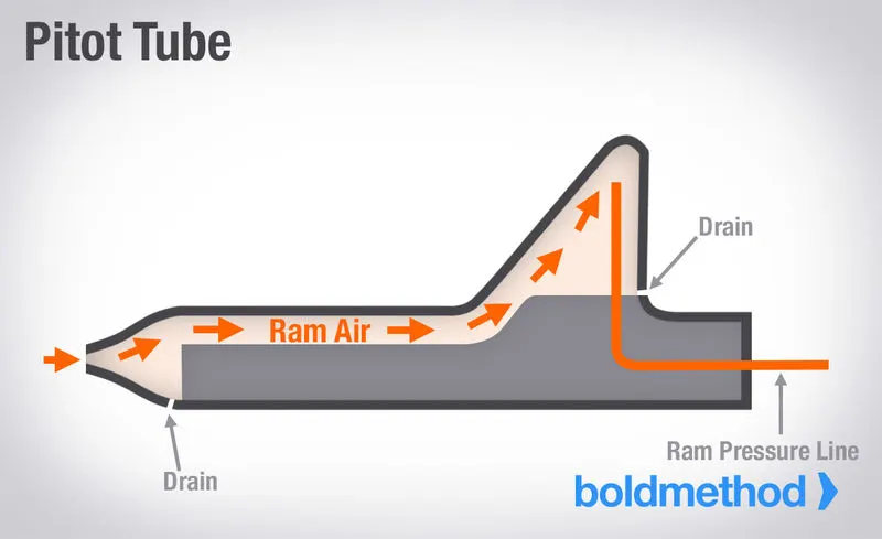
- Airspeed:- An aircraft on the ground in still air is subject only to atmospheric (static) pressure (S). However, in-flight, the leading edges of an aircraft are subject to additional dynamic pressure. This results in a total pitot pressure (P) on the leading edges of dynamic pressure plus static pressure.
Pitot = Dynamic + Static
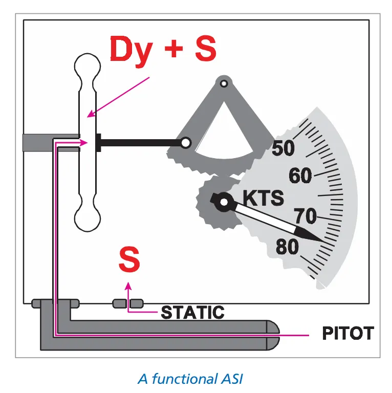
The pitot head senses pitot pressure and the static/vent senses static pressure. These two pressures are fed to the airspeed indicator, a differential pressure gauge, which measures their difference (the dynamic pressure). Dynamic pressure is related to airspeed, because:-
Dynamic Pressure = ½ ρV²
Where V is true airspeed (TAS) and ρ is the density of the surrounding air. The ASI measures airspeed by measuring dynamic pressure, displaying the result (usually in knots) on a suitably calibrated scale i.e,1 knot is 1 nautical mile per hour. The device which is been used for measuring Airspeed is called Air Speed Indicator and below is the construction, errors and important terms associated with the AirSpeed.Constructions It is important to construct a device in which static pressure is subtracted from pitot (total) pressure to isolate dynamic pressure. Dynamic pressure cannot be directly measured; it must be established from the difference between the pitot and static pressure. Static pressure is fed into a hermetically-sealed instrument case, the pitot pressure being piped to a thin metal capsule capable of expansion and contraction.
The layout is shown in Figure Static pressure present on both the inside and the outside of the capsule's metal walls and so cancels. Therefore the pressure differential between the inside and outside of the capsule is (Dy + S) - S which is Dynamic.
Therefore, expansion or contraction on the capsule will be proportional to the changes in dynamic pressure produced by changes in airspeed. The capsule movements are transmitted by a temperature-compensated magnifying linkage to the pointer indicating airspeed on the face of the ASI.
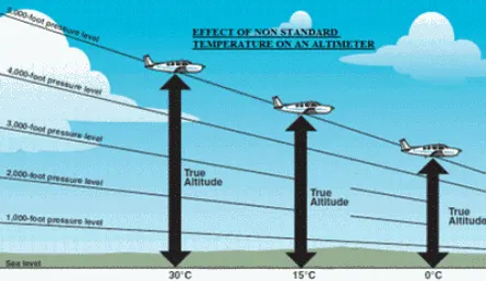
Errors Blockage During the climb, if the pitot is blocked then the readings will be more than actual. During the descend if the pitot is blocked then the readings will be less than actual. During the climb, if the static blocks then the readings will be less than the actual. During the descend of the static blocks then the readings will be more than the actual. Leakage if there is a leakage in pitot pressure then the ASI will be less than the actual. If there is a leakage in the static pressure then the ASI will be more than the actual Indicated Manufacturing imperfections and usage result in small errors which are determined on the ground under laboratory conditions by reference to a datum instrument. A correction card can be produced for the speed range of the instrument. position it is also known as ‘pressure’ error, this happens mainly from the sensing of incorrect static pressure. Position errors throughout the speed range are determined by the aircraft manufacturer during the test flying programme for a particular aircraft type. It is not unusual to compile a joint correction card for position and instrument errors and place it in the aircraft near the ASI concerned. Density The ASI under-reads the true speed at altitude as density is less than 1225 grams/cubic metre, this discrepancy being called ‘density error’. If the density is greater than ISA at MSL, the ASI will over-read the true speed Compressibility Air is compressible and the pressure produced in the pitot tube is higher than it would be for an ideal incompressible fluid, for which the dynamic pressure is ½ρV2.
The ASI is calibrated to allow for this complex compressible flow formula assuming a density of 1225 g/cu metre. If the density is any lower, the standard correction for compressibility will be in error.Because of this, the instrument will over-read, IAS and CAS will be too high, and a subtractive compressibility correction will have to be applied The correction, which exceeds 20 knots if TAS is near the speed of sound, can be obtained from graphs or tables, or it can be applied by high-speed navigation computers. If the TAS is less than 300 knots, the error is small enough to be ignored in the TAS calculation from IAS. 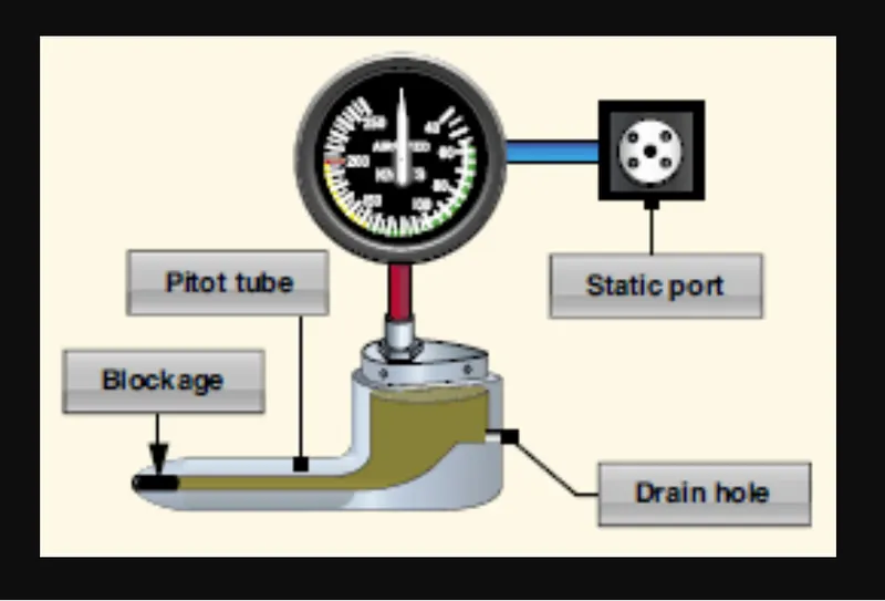
important Terms Related to speed indicated Air Speed (IAS):- Calibrated Air Speed (CAS):- CAS is IAS corrected for Instrument and Position (Pressure) Error. Equivalent Air Speed (EAS):- Equivalent Airspeed is CAS corrected for Compressibility Error only. True Air Speed (TAS):- EAS is TAS corrected for Density error. Ground Speed(GS):- TAS corrected with wind velocity gives Ground Speed 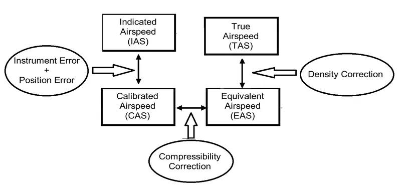
Important Speeds `V_(NO)` = The maximum normal operating limit speed. `V_(NE)` = The Never Exceed speed `V_(S0)` = The stall speed or the minimum steady flight speed in the landing configuration. `V_(S1)` = The stall speed or the minimum steady flight speed in a specified configuration. `V_(FE)` = The maximum Flap Extension speed `V_(YSE)` = the best rate of climb speed with one engine failed 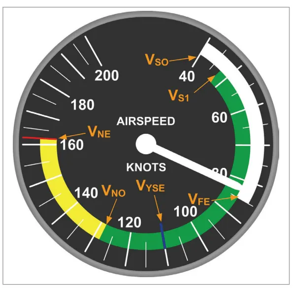
-
- As we all know that aircraft are always design to fly in the air not to drive on the ground. So, manufacturers design them with very powerful engines and they are so powerful that thinking of turning on the ground can be very hazardous and below are some listed things which are always taken into consideration as for all the ground staffs and pilots:-
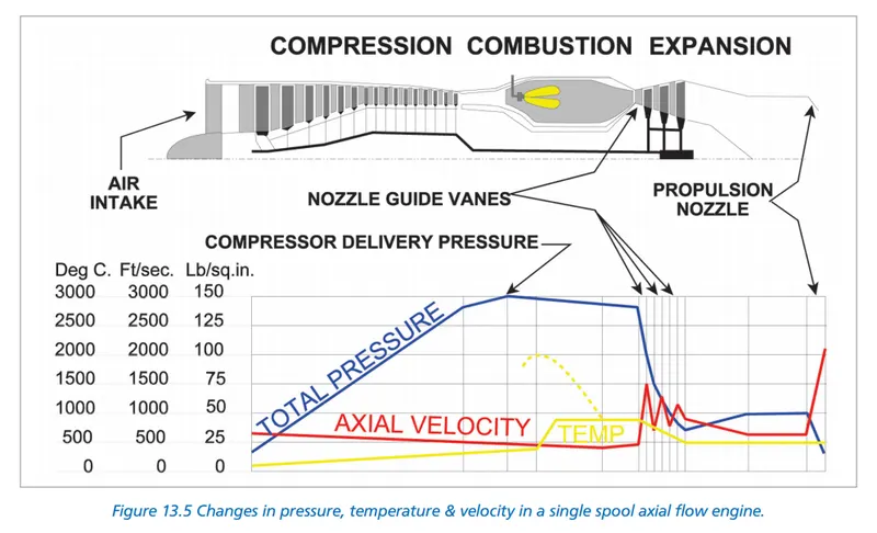
- The engines are so power full that even when those are on and running at idle power their thrust and suction of air can make anyone thrown away to miles, and they suck so much air that they can make human flesh into millions of pieces.
- The engines are very fragile while running and they can be easily damaged and those are very expensive, and in-ground they are not used.
- When every aircraft is cleared from the security then it is required for pushback. and thee aircraft cannot be moved or move back while in-ground below are some of the things which are taken into account for pushback and taxing:-
For pushback, there are towing vehicles used which are very powerful torque and have a very good capacity for pushing the aircraft back these vehicles are very useful for pushback. moving the aircraft to the maintenance and to guide the bigger aircraft for the parking place. All the commercial and bigger aircraft another engine which is called auxiliary power unit these APUs are mounted in the tail of the aircraft and the aircraft can rely on that as they are more efficient and uses less fuel and safe in-ground. these APUs help them in the ground while taxing, in case of service and case of emergency while the engine gets fail in the air. The APUs are nothing they are only some short of Generators that have very little voltage and high frequency, the power output of the APUs is 115V and 400Hz. Leaving to this there is also another thing which helps the aircraft in the ground that are GPUs which are also known as GRound Power Unit these are only the power converters which are also giving the same output i.e., 115v and 400Hz 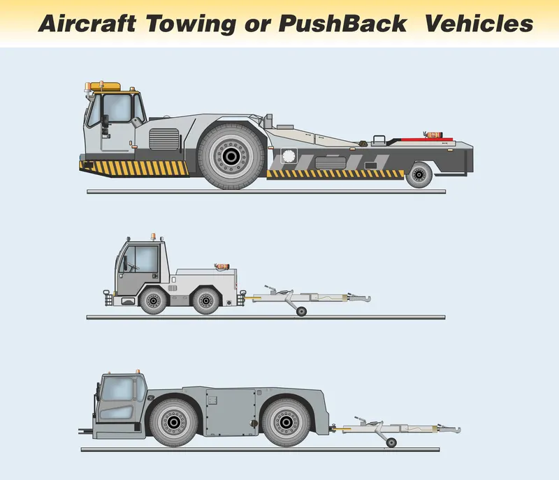
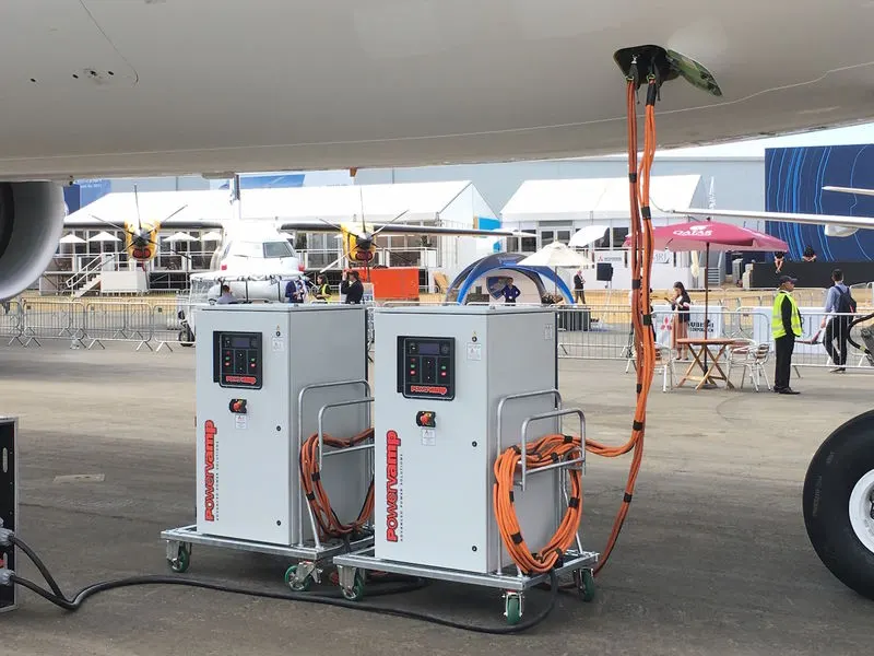
- let us discuss one by one:-
- Take-Off Power:-
- The takeoff power is never full percentage it is generally about 50 to 70% of the total power and it depends on the speed of the aircraft, thrust and also in the gradability of the airfield.
- Taking about speed different aircraft have different speed so for better understanding the pilots use speeds name if the aircraft exceeds the `V_1` speed then it cannot be stooped in any condition and the `V_r` speed is the speed when reached then the pilots pull up and the aircraft is now in the air and is in climbing and the speed is kept inside `V_1` speed range until it reaches the level.
- Now the thrust is calculated by this formula:-
Gross thrust (Fg) is the thrust produced when the engine is not moving through the air. The acceleration given to the gas is the difference in velocity of the unit of air entering the intake (Vi), and the unit of air exiting the nozzle (Vo). Substituting into F = ma:
`F_g = (W_a *(V_o -V_i))/g`where:
Wa = Weight of air per second
Vo = exit velocity of air in ft/sec
Vi = inlet velocity of air in ft/sec
g = gravitational force, 32.2 ft/sec2 - The gradability of the airfield plays a vital role if the gradability of the runway is more than the required speed and thrust is more as well as if the runway is more then the thrust is also less required, if the runway is having a slop then it requires less time for take-off.
- Rolling resistance:-
-
Rolling resistance sometimes called rolling friction or rolling drag is the force resisting the motion when a body (such as a ball, tire, or wheel) rolls on a surface.
The "rolling resistance coefficient" is defined by the following equation: `F= C_(rr) *N`
where;
F= is the rolling resistance force
`C_(rr)`= is the dimensionless rolling resistance coefficient or the coefficient of rolling friction (CRF) and
N=is the normal force, the force perpendicular to the surface on which the wheel is rolling.
As an alternative to using one can use, which is a different rolling resistance coefficient or the coefficient of rolling friction with the dimension of length. It is defined by the following formula:`F = (N*b)/r`
where;
F = is the rolling resistance force
r = is the wheel radius,
b = is the rolling resistance coefficient or the coefficient of rolling friction with a dimension of length, and
N = is the normal force
-
- Tyre Pressure:-
- Aircraft wheels are fitted with pneumatic tyres which may be tubeless or have an inner tube. Tubes tend to be fitted to light and older aircraft. Tyres are usually inflated with nitrogen which absorbs shock and supports the weight of the aircraft, while the cover restrains and protects the tube from damage, maintains the shape of the tyre, transmits braking and provides a wearing surface.
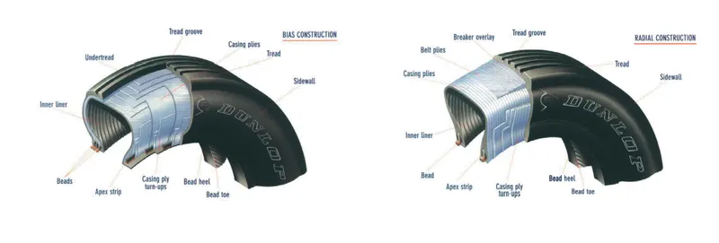
- The difference in landing speeds, loading, landing surfaces and landing gear construction of aircraft makes it necessary to provide a wide range of tyre sizes, types of tyre construction and
inflation pressures. - There are four main categories of tyre pressures, which are as follows:
- Low Pressure: Designed to operate at a pressure of 25 lb. to 35 lb. per sq. in, (1.73 - 2.42 bar), used on grass surfaces.
- Medium Pressure: Operates at a pressure of 35 lb. to 70 lb. per sq. in, (2.42 - 4.83 bar) and is used on grass surfaces or medium-firm surfaces without a consolidated base.
- High Pressure: Operates at a pressure of 70 lb. to 90 lb. per sq. in, (4.83 - 6.21 bar) and is suitable for concrete runways.
- Extra-High Pressure: Operates at pressures of over 90 lb. per sq. in (some tyres of this type are inflated to 350 lb. per sq. in) (6.21 - 24.2 bar), the tyre is suitable for concrete runways.
- Tyres in use must be kept inflated to the correct pressures using nitrogen or other inert gas (with a maximum 5% oxygen content) as under-inflated tyres may move (creep) round the wheel, overinflated tyres will cause other types of failure. It is estimated that 90% of all tyre failures can be attributed to incorrect air pressure. Modern aircraft can even display tyre pressures on the
electronic systems monitoring screen.
- Aircraft wheels are fitted with pneumatic tyres which may be tubeless or have an inner tube. Tubes tend to be fitted to light and older aircraft. Tyres are usually inflated with nitrogen which absorbs shock and supports the weight of the aircraft, while the cover restrains and protects the tube from damage, maintains the shape of the tyre, transmits braking and provides a wearing surface.
- Break Force while Landing:-
- In common with most braking systems, aircraft wheel brakes function by using friction between a fixed surface and a moving one to bring an aircraft to rest, converting kinetic energy into heat energy. The amount of heat generated in stopping a large modern aircraft is enormous, the problem of dissipating this heat has been a challenge to aircraft designers and scientists for years. As progress has been made in this direction, so aircraft have got faster and heavier and the problem worse.
- The ideal answer, of course, would be to build runways of sufficient length so that an aircraft would not need to use its brakes at all, but the prohibitive cost of building runways 4 and 5 miles long makes it a non-starter
- Plates And DIsk Breaks:
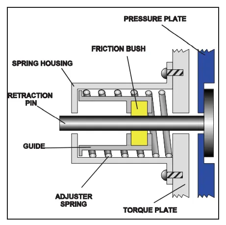
All modern aircraft now use plate brakes operated by hydraulic systems as their means of slowing down or stopping. This system uses a series of fixed friction pads, bearing on or gripping, one or more rotating plates, similar in principle to disc brakes on a car.
The number of friction pads and rotating plates that are used is a matter of design and wheel size, a light aircraft would be able to utilise a single plate disc brake whereas a typical arrangement on a large aircraft would be a multi-plate unit similar to the one illustrated in Figure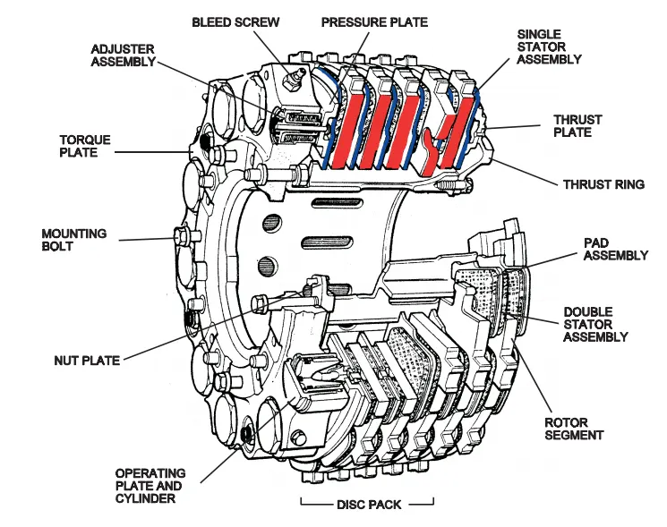
- Break Realise:
When the pilot releases the pressure on the brake pedals, the brake adjuster assemblies will move the pressure plate away from the stators and rotor assemblies, thus allowing them to move slightly apart. The internal construction of the brake adjuster assemblies allows them to maintain a constant running clearance when the brake is off thereby automatically compensating for brake wear.
If the return spring inside the adjuster assembly ceases to function, or if the unit is wrongly adjusted, then they could be the cause of a break not releasing correctly. This is termed brake drag.Brake drag will generate a lot of heat and can be responsible for Brake Fade occurring sooner than it otherwise would. Air in the hydraulic system of the brake can also cause the brakes to drag.
- Break Temprature Indicators:
Sensors are arranged to sample the temperature of the brakes of each wheel. An indicator can be used to display the temperature of each pair of wheels as selected on the system control panel.
The brake temperatures are constantly monitored by the system, if the temperature of any brake assembly rises above a predetermined level then a “HIGH TEMP” indicator light illuminates. Switch selection on the control panel will now enable the operator to locate the wheel brake or brakes which are triggering the alarm. Should any brake temperature go above that level at which the High Temp warning light illuminates, then a brake “OVERHEAT” caption will come on.
This last event is duplicated on the Central Warning System. This illustrates a Brake Temperature Warning Panel.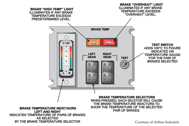
- Reverse Thrust:
- Modern aircraft braking systems, which incorporate anti-skid units and other sophisticated devices are extremely efficient, bad runway conditions however can reduce the ability of even the most refined braking systems to the point where they become a liability. The addition of a Reverse Thrust capability has improved the situation so much that landing a modern aircraft on a wet and/or icy runway in crosswind conditions need now hold no terrors for the capable pilot. The difference in stopping distance in an aircraft with and without reverse thrust is quite marked. Reverse thrust is selected immediately the weight of the aircraft is firmly on the mainwheels and coupled with ground spoilers can reduce the landing distance dramatically without producing friction at the wheels.
i. Clamshell Doors The name “Clamshell” has been applied to this system of reverse thrust because of the shape of the reverse thrust doors, which resembles that of a clamshell. The reverser doors are usually pneumatically operated and use high-pressure compressor (P3) air as the power source. Pneumatic rams move the doors from their stowed (Forward Thrust) position to their deployed (Reverse Thrust) position.
In their stowed position, the clamshell doors cover Cascade Vanes which are revealed when the doors move to the deployed state. Whilst deployed, the clamshell doors close the normal exhaust gas exit and it escapes through the Cascade Vanes in a forward direction so that the forward motion of the aircraft is opposed. The lower cascade vanes, while directing the jet thrust forward, are angled so that the exhaust has an outboard angular component as well. This minimizes the chances of debris and hot gases being reingested into the engine intake during the use of reverse thrust.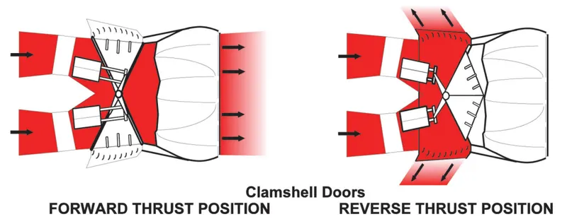
ii. Bucket Doors The Bucket Reverser system is normally hydraulically operated. The rear of the exhaust pipe is shaped like two halves of a bottomless bucket which are hinged to enable them to swing backwards when selected to deflect the exhaust gas forward. 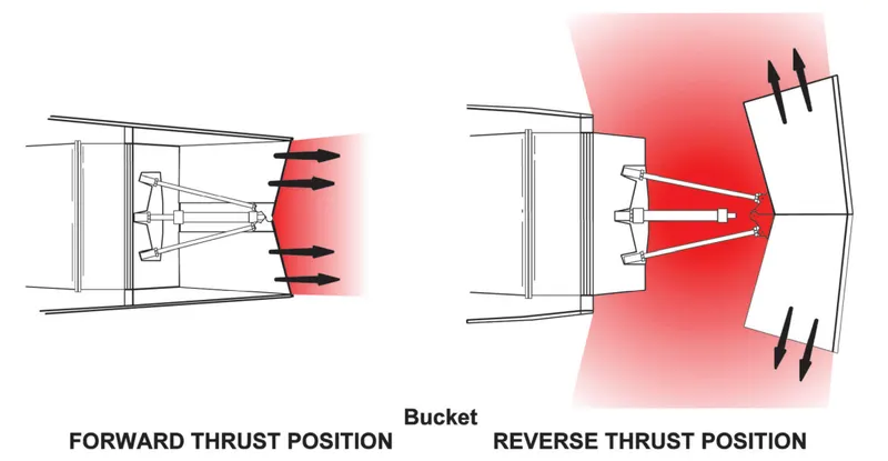
iii. Blocked Doors This system is only used on High Bypass Ratio FanJet Engines. The essential difference between this system and the Clamshell Door and Bucket systems is that while the latter uses the hot exhaust as the means of reverse thrust, the ‘Blocker’ system, as its name suggests, blocks and diverts the Cold Bypass Airstream only.
Operation of the system is initiated, as are the other two systems, by the movement of reverse thrust levers in the cockpit, each engine with a reverse thrust capability has a reverse thrust lever.
In the case of the blocker system, the speed and direction of an Air Motor are determined by the operation of the reverse thrust lever. The output of the air motor drives through flexible shafts to open or close the Blocker Doors, which, by their movement, expose or cover Cascade Vanes to direct the By-Pass air where it is required.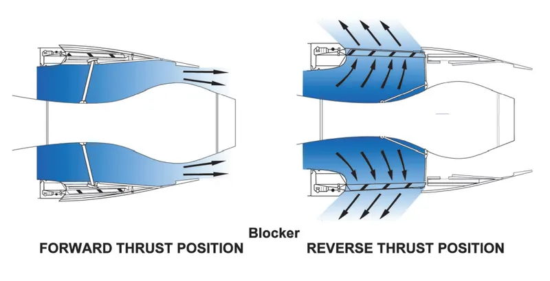
- Modern aircraft braking systems, which incorporate anti-skid units and other sophisticated devices are extremely efficient, bad runway conditions however can reduce the ability of even the most refined braking systems to the point where they become a liability. The addition of a Reverse Thrust capability has improved the situation so much that landing a modern aircraft on a wet and/or icy runway in crosswind conditions need now hold no terrors for the capable pilot. The difference in stopping distance in an aircraft with and without reverse thrust is quite marked. Reverse thrust is selected immediately the weight of the aircraft is firmly on the mainwheels and coupled with ground spoilers can reduce the landing distance dramatically without producing friction at the wheels.
- Speed Breaks:
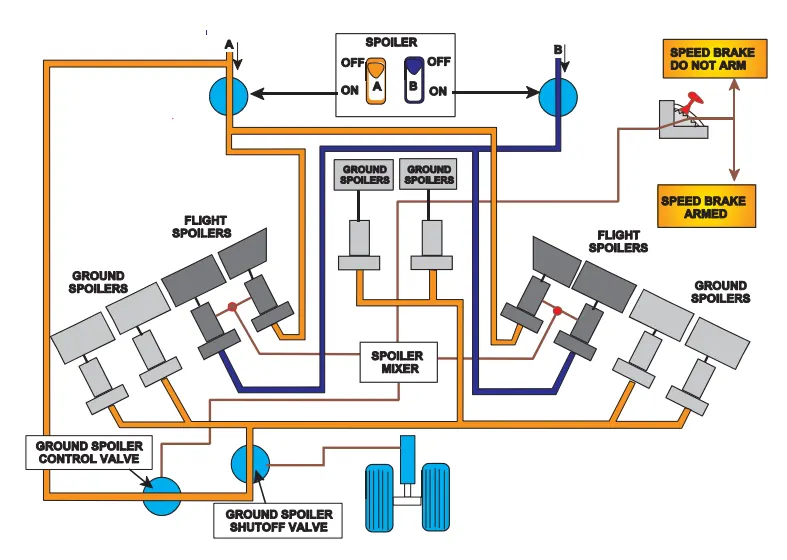
Speedbrakes consist of flight spoilers and ground spoilers. The speed brake lever controls a spoiler mixer, which positions the flight spoiler control units, Power Control Units (PCU’s),
and a ground spoiler control valve. The surfaces are actuated by hydraulic power supplied to the PCU’s or actuators on each surface. Ground spoilers operate only on the ground, due to a ground spoiler shut-off valve which remains closed until the main landing gear operates a ‘weight on’ switch.
With lateral controls in neutral, the application of the speed brakes will cause the flight spoilers to rise equally. When speed brakes are applied on the ground, the ground spoilers will also rise. Moving the speed brake control lever will provide input to the spoiler mixer via a mechanical system.
The spoiler mixer conveys the speed brake signals to a ground spoiler control valve and the flight spoiler actuators. Ground spoiler shut off valve, fitted in the hydraulic system downstream of the spoiler control valve, is operated by a ‘weight on’ switch.
Speed brake control may also be applied by an electric speed brake lever actuator. When ‘armed’, the actuator will drive the speed brake lever to the ‘full up ‘ position, raising the flight and ground spoilers when the landing gear wheels rotate on touchdown. If the engine thrust levers are opened up again on the landing run, the actuator will sense the aborted landing and will lower the flight and ground spoilers.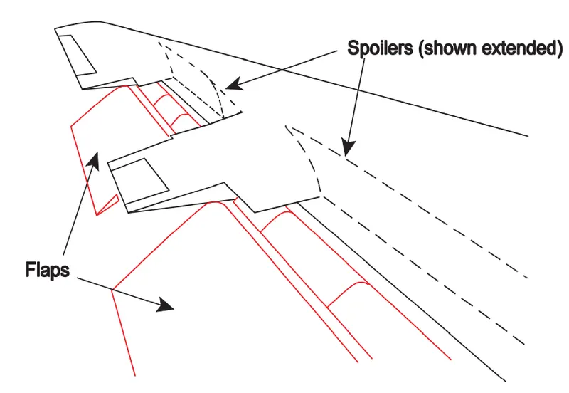
- Take-Off Power:-
- Only Calculation, no Theory
- Only Calculation, less Theory
Solutions:-
- Only Theory
- Only Theory
- Only Theory
- Only Theory
- Only Theory
- Below are my assumption:-
ALL ARE OF BOEING 747F AIRCRAFT Parameter Name Values Mass Of The Aircraft (Kg) 447,700 Acceleration Of g (m/`s^2`) 9.81 Aircraft Tyre Pressure (Bar) 15 Aircraft Velocity (Kmph) 12 Mass of the Towing Vehicle (kg) approx 50000 Tyre Pressure of Towing Vehicle 32 Velocity Of the Towing Vehicle (kph) 11 Density Of Air (kg/`m^3`) 1.3 Frontal Area (`m^2`) 21 Rolling Resistance Of Aircraft (`mu_(rr)`) 0.008 Rolling Resistance of Towing Vehicle (`mu_(rr)`) 0.0047 Coefficient Of drag (`C_(d)`) 0.52 The radius of Towing Vehicle wheel (mm) 0.38 Towing Time (min) 3 Rolling Resistance For the Aircraft is calculated by using a Formula.
The value of `mu_(rr` can be calculated by this formula`F_r = mu_(rr) * m *g` `mu_(rr) = 0.005 + (1/p) * ((0.01 + 0.0095)* (v/100)^2)` Formula For Calculating Drag Force is below `F_D = C_d * A * p * V^2/2` On substituting the values of the Aircraft the force will come `mu_(rr) = 0.005 + (1/15) * ((0.01 + 0.0095)* (12/100)^2)` Or, `mu_(rr) = 0.005018` `F_r = 0.005018 *447700*9.81` Or, `F_r = 22041.9 N` -------------------------------- Equation 1 On substituting the Values Of the Towing Vehicle Force will Come `mu_(rr) = 0.005 + (1/32) * ((0.01 + 0.0095)* (11/100)^2)` Or, `mu_(rr) = 0.0050073` `F_r = 0.0050073 * 50000 * 9.81` Or, `F-r = 2456.11 N` --------------------------------- Equation 2 Calculating the Drag Force `F_D = 0.52 * 1.25 * 0.5 * 15^2/2` Or, `F_D = 36.5625 N` --------------------------------- Equation 3 Now the Total Power i.e., Adding All the Three Equation `F_(t) = 2456.11 + 22.41.9 + 36.5625` Or, `F_t = 24534.57 N` Total Power For all that Force is `P = v * F_t` Or, `P = 24534.52 * (11*(5/18))` Or, `P = 74.96 Kw` Total Torque Required For moving the Aircraft `T = F_t * r` Or, `T = 24534.52 * 0.38` Or, `T = 9323.1176 N` Total Energy Required for those operation `E = P *T` Or, `E = 74.96k * 180/3600` Or, `E = 3.748kwh` - From the above, I got the idea of the energy that is been used for towing an aircraft. Now I have to build a Power Train with a Power Rating of 80Kwatt
For this, I got the idea and I am choosing 3-phase Induction Motor SL. No. Parameters Ratings 1. Power Rating 80Kw 2. Number Of phases 3 3. Frequency in Hz 60 4. Efficiency 80% 5. Rated Voltage 240V,480V 6. Rated Current 333.3A, 166.7A Power Input for the vehicle:- `P = V*I` Or, `P = 240 * 166` Or, `P = 80kw` Energy Required for the Towing truck, Assume that the truck is used for around 20 min converting 20 min into hours `= (20*60)/(3600)` Or, `= 0.333` Energy `E = P *t` Or, `E = 80 * 0.333` Or, `E = 26.67kwh` Duty Cycle For controlling the speed of the Towing Vehicle `D = T_(on)/ T_(Total)` Or, `D = 62.6/80` Or, `0.82` Powertrain:
As the name suggests, the powertrain provides power to the vehicle. Powertrain refers to the set of components that generate the power required to move the vehicle and deliver it to the wheels.
An EV powertrain has 60% fewer components than the powertrain of an ICE vehicle. The components are described below.
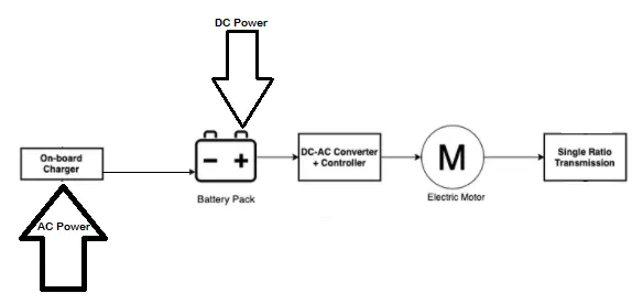
Components 1. Battery Pack:- The battery pack is made up of multiple Lithium-ion cells and stores the energy needed to run the vehicle. Battery packs provide direct current (DC) output.
2. DC - AC Converter:– The DC supplied by the battery pack is converted to AC and supplied to the electric motor. This power transfer is managed by a sophisticated motor control mechanism (also referred to as Powertrain Electronic Control Unit) that controls the frequency and magnitude of the voltage supplied to the electric motor to manage the speed and acceleration as per the driver’s instructions communicated via acceleration/brakes.
3. Electric Motor:– Converts electrical energy to mechanical energy, which is delivered to the wheels via single ratio transmission. Many EVs use motor generators that can perform regeneration as well.
4. Onboard Charger:– Converts AC received through charge port to DC and controls the amount of current flowing into the battery pack.
Apart from the above core parts, there are multiple hardware and software components in an EV powertrain. Electronic Control Units (ECUs) are basically software programs integrated with the powertrain components to help data exchange and processing, e.g. Powertrain ECU mentioned above. There are several small ECUs in an EV that perform specific functions. The communication between different ECUs in a vehicle is commonly carried over CAN protocol. More examples of core ECUs are:
1. Battery Management System (BMS): - A BMS continuously monitors the state of the battery and is responsible for taking necessary measures in case of a malfunction. BMS performs cell balancing to deliver maximum efficiency from the battery pack. It is responsible for communication with other ECUs and sensors, as well as EVSEs to control the charging input, check the current state of charge, and share data about battery specifications.
2. DC-DC Converter:– A battery pack delivers a fixed voltage, but the requirement of different accessory systems (e.g. wipers, lights, infotainment system, mirror control) in the EV would vary. The DC-DC converter helps distribute power to different systems by converting the output power from the battery pack to the expected level. After conversion, power is delivered to respective smaller ECUs via a wiring harness.
3. Thermal Management System:- Responsible for maintaining optimum operating temperature range for powertrain components.
4. Body Contro Module (BCM):- The BCM is responsible for supervising and controlling the functions of electronic accessories such as power windows, mirrors, security, and vehicle access control.
Block Diagram:-
7.Below is the Block Diagram
 |