Project-1: Powertrain for aircraft in runways
AIM:-
- Search and list out the total weight of various types of aircrafts.
- Is there any difference between ground speed and air speed?
- Why is it not recommended to use aircraft engine power to move it on the ground at Airport?
- How does an aircraft get pushed to the runway when its ready to take off?
- Learn about take off power, tyre design, rolling resistance, tyre pressure, brake forces when landing.
- With necessary assumptions, calculate the force and power required to push / pull an aircraft by a towing vehicle.
- Design an electric powertrain with a type of motor, it’s power rating, and energy requirement to fulfill aircraft towing application. Estimate the duty cycle range to control the aircraft speed from zero to highest. Make all required assumptions. Prepare a table of assumed parameters. Draw a block diagram of powertrain.
Study1:-Search and list out the total weight of various types of aircrafts.
Manufacturer's empty weight (MEW)
Also called Manufacturer's Weight Empty (MWE) or Licensed Empty Weight
It is the weight of the aircraft "as built" and includes the weight of the structure, power plant, furnishings, installations, systems and other equipment that are considered an integral part of an aircraft.
This excludes any baggage, passengers, or usable fuel.
Zero-fuel weight (ZFW)
This is the total weight of the airplane and all its contents (including unusable fuel), but excluding the total weight of the usable fuel on board.
As a flight progresses and fuel is consumed, the total weight of the airplane reduces, but the ZFW remains constant.
Maximum zero fuel weight (MZFW) is the maximum weight allowed before usable fuel and other specified usable agents (engine injection fluid, and other consumable propulsion agents) are loaded.
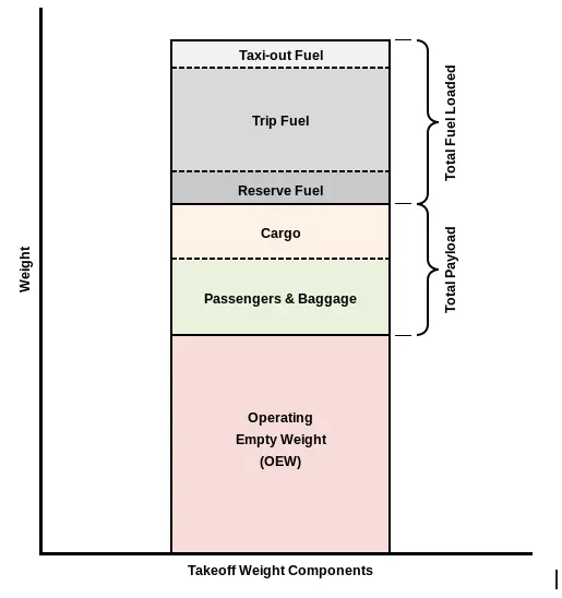
Operating empty weight (OEW) (Roughly equivalent to basic empty weight on light aircraft)
It is the basic weight of an aircraft including the crew, all fluids necessary for operation such as engine oil, engine coolant, water, unusable fuel and all operator items and equipment required for flight but excluding usable fuel and the payload.
Payload
It is the carrying capacity of an aircraft. It includes cargo, people, extra fuel. In the case of a commercial airliner, it may refer only to revenue-generating cargo or paying passengers.
Maximum takeoff weight (MTOW)
This is the maximum weight at which the pilot of the aircraft is allowed to attempt to take off.
Regulated takeoff weight (RTOW)
Depending on different factors (e.g. flap setting, altitude, air temperature, length of runway), RTOW or maximum permissible takeoff weight varies for each takeoff. It can never be higher than MTOW.
Maximum landing weight (MLW)
This maximum weight at which an aircraft is permitted to land.
The following image depicts takeoff weight components.
Maximum ramp weight (MRW) (or) maximum taxi weight (MTW)
It is the maximum weight authorized for maneuvering (taxiing or towing) an aircraft on the ground.
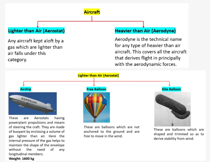
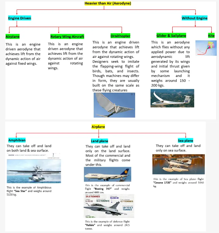
Aircrafts types and Explanation:-
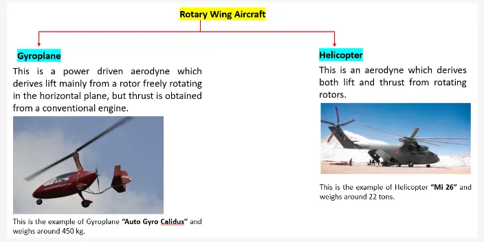
Reference:-https://en.wikipedia.org/wiki/Aircraft
- weights of Aircrafts:-
Reference:-https://docs.google.com/spreadsheets/d/1zGNFDGX2vAEasFGvt5OZuazQDxbDQY2zrEW881_QZS0/edit#gid=0
| Type | MTOW [kg] | MLW [tonnes] | TOR [m] | LR [m] | ICAO category | FAA category |
| Antonov An-225 | 640,000 | 591.7 | 3500 | Heavy | Super | |
| Scaled Composites Model 351 Stratolaunch | 589,670 | 3660 | Heavy | Super | ||
| Boeing 747-8F | 447,700 | 346.091 | 3100 | 1800 | Heavy | Heavy |
| Boeing 747-8 | 443,613 | 306.175 | 3100 | Heavy | Heavy | |
| Douglas DC-8-51 | 125,000 | Medium | Large | |||
| Boeing 757-300 | 124,000 | 101.6 | 2550 | 1750 | Medium | Large |
| Boeing 707-120B[15] | 117,000 | 86.3 | Medium | Large | ||
| Boeing 757-200 | 116,000 | 89.9 | 2347 | 1555 | Medium | Large |
| Boeing 720B[16] | 106,000 | 79.5 | Medium | Large | ||
| Boeing 720[16] | 104,000 | 79.5 | Medium | Large | ||
| Embraer Phenom 100 | 4,800 | 4.43 | 975 | 741 | Light | Small |
---------------------------------------------------------------------------------------------------------------------------------------------------------
Study2:-Is there any difference between ground speed and air speed?
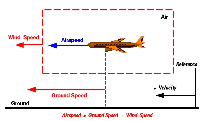
From above figure we have to differentiate the ground and Airspeed
Ground Speed
For a reference point picked on the ground, the aircraft moves relative to the reference point at the ground speed. Ground speed is also a vector quantity so a comparison of the ground speed to the wind speed must be done according to rules for vector comparisons.
Airspeed
The important quantity in the generation of lift is the relative velocity between the object and the air, which is called the airspeed. Airspeed cannot be directly measured from a ground position, but must be computed from the ground speed and the wind speed. Airspeed is the vector difference between the ground speed and the wind speed.
Airspeed = Ground Speed - Wind Speed
Therefore we observer that Airspeed is Equal to the Ground Speed.
--------------------------------------------------------------------------------------------------------------------------------------
Study3:-Why is it not recommended to use aircraft engine power to move it on the ground at Airport?
- We are assuming passenger commuter aircraft and large airliners. Aircraft move using their own engine power all the time on the airport apron and taxiways under their own power to go towards runways and after landing taxi to their assigned gate.
- The only time they use external assistance is to pushback from the gate. Large turbofan aircraft need help to reverse via a pushback tractor. The engines are turned on after the pushback is complete and the aircraft can move forward under It’s own power.
- To be accurate, some aircraft can reverse using a variable pitch prop or thrust reversing on turbofans but generally reversing is done via pushback tractors. Blasting jet reversers blows debris In the crowded gate area creating foreign object damage hazard for adjacent aircraft, gate equipment or terminal waiting area glass windows.
-----------------------------------------------------------------------------------------------------------------------------------------------
Study4:-How an aircraft is pushed to runway when its ready to take off?
- When Aircraft is ready with all passengers and unloading the luggage and cargo materials in to the Aircraft,pushback is an Airport procedure during which an Aircraft is pushed backwards away from an Airport External Power.
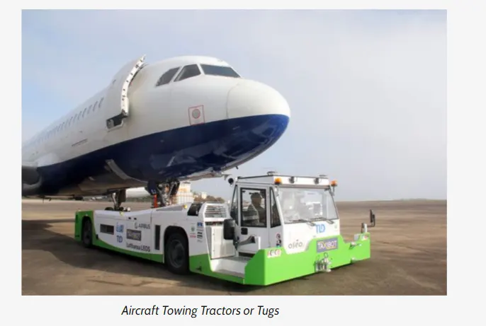
- Pushback is when an aircraft is pushed backwards away from the airport gate by vehicles called tugs or pushed tractors.
- Closer to departure, an aircraft tug will park right in front of the nose wheel.
- The tug might be directly attached to the plane's nose gear with a tow bar, or could be a "wheel-lift" tug.
- These tugs cradle the nose gear, then lift it up before moving the plane. That gives the tug driver control over the plane's direction during pushback.
- New taxi technologies are appearing, like pilot-controlled tugs, and electric motors mounted to the plane's landing gear. Both promise to save fuel, and reduce airport noise.
-----------------------------------------------------------------------------------------------------------------------------------------------------
Study5:-Learn about take off power, tyre design, rolling resistance, tyre pressure, brake forces when landing.
Refernce link:-https://www.youtube.com/watch?v=F077WDnB8P8
1.Take off power:-
* For Take off we have to increase the lift force with Various Techniques like
- High Speed
- High angle of attack
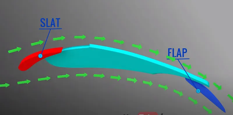
- Use of flap and slat
* It says that Lift > weight for Takeoff period
* The pilots use all different Techniques to Takeoff the Aircraft.
*It states that when the Aircraft speed is high enough the pilot activates the FLAP and SLATS.Lifts increase due to the FLAP and SLATS.
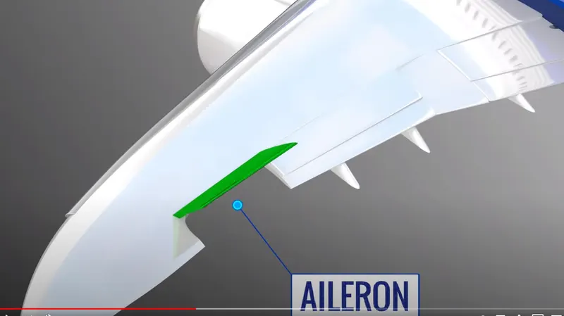
* When aircraft is ready for the Takeoff.They activates Aleron Upwards and tail force will be increases and Aleron figure shows below
* Takeoff speed varies with the Air density,Aircraft Gross weight and Aircraft Configuration.
* For Light Aircraft Usually full power is used during Takeoff.
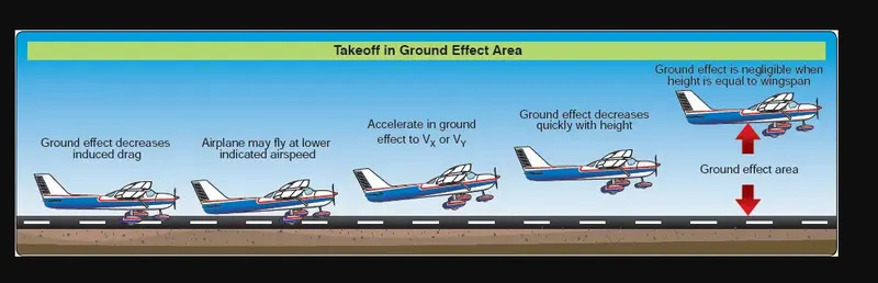
Takeoff image of Aircraft:-
(2.)Tyre design:-
Reference Link:-https://www.youtube.com/watch?v=xoo0oAyxbLY
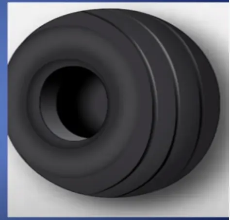
Aircraft Tires and Tubes
- Aircraft Tires may be tube tyre or tubeless
- They support the weight of aircraft while it is on ground and provide necessary traction for braking and stopping.
- Tires also help to absorb the shock of landing and cushion the roughness of takeoff,rollout and taxi operations.
Tyre Construction
- An aircraft tire is constructed for the purpose of its series.
- An automobile or truck tire, does not have to carry a load for a long period of continuous operation
- An aircraft tire must have absorbed high impact loads of landing and be able to operate at high speeds even if only for a short time.
- The deflection built into an aircraft tire is more than twice that of an automobile tire.
- Only tires designed for an aircraft as specified by the manufacturer should be used.
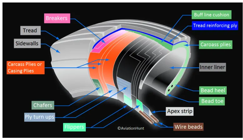
- It is used to understand tire construction to identify the various components of a tire and the functions that contribute to the overall characteristics of the tire
Retreading – Retreading is methods of restoring a worn tyre by renewing the tread area or by renewing the tread area plus one or both sidewalls. Repairs are included in the tyre retreading process.
Load Rating – Load rating is the maximum permissible load at a specified inflation pressure.
Ply Rating – Ply Rating is used to identify the maximum recommended load rating and inflation pressure for a specified tyre. It is an index of tyre strength.
Speed Rating – The speed rating is the maximum takeoff speed to which the tyre has been tested.
Skid Depth – Skid depth is the distance between the tread surface and the deepest groove as measured in the mould.
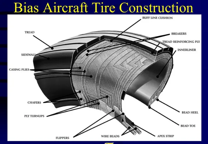
Bias ply Aircraft Tire Construction.
- A bias ply tire has the fabric bias oriented with and across the direction of rotation and sidewall.
- Since fabric can stretch on the bias the tire is flexible, and can absorb loads
- Strength is obtained by adding piles.
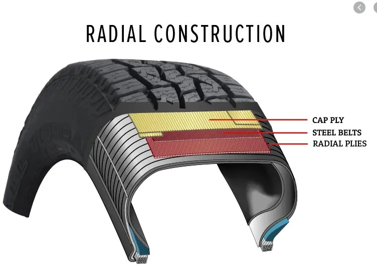
Radial ply Aircraft Tire Construction
- A radial ply tire has the fabric bias oriented with and across the direction of rotation and tire sidewall
- This restricts flexibility directionally and the flexibility of sidewall while it strengths the tire to carry heavy loads.
(3). Rolling Resistance
- Rolling Resistance force is mainly explained by the Tyre when vehicle moves on surface.
- Rolling resistance can be explained as below formuale
`F_(rr)=mu_(rr)*m*g
Where m,g is weight in Newton's
`mu_(rr)` is Coefficient of Rolling resistance
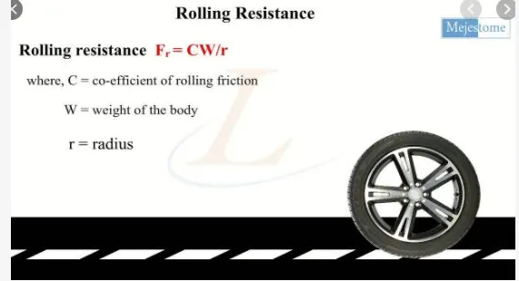
- Coefficient of rolling resistance depends on many factors like tyre pressure,tyre temperature,material of tire,road Roughness and Liquids on Road.
4.tyre pressure:-
-
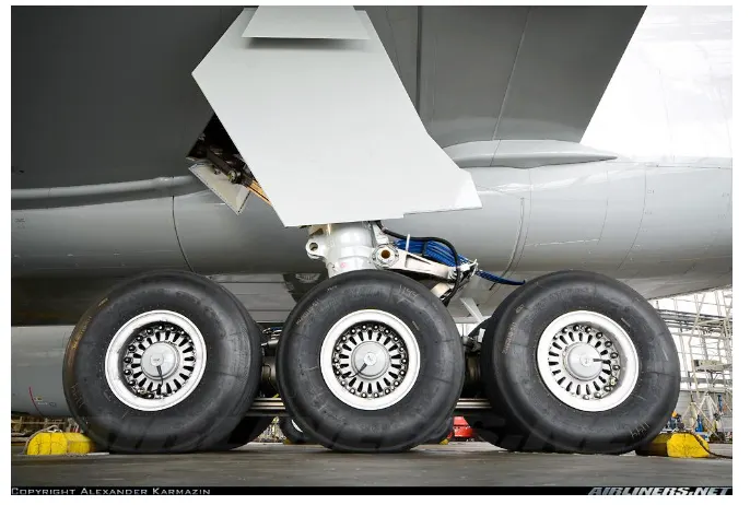
Depends on the weight of the plane and number of tires it has, but generally the cold pressure is between 200 and 300+ psi.
-
They are rubber, like a car tire but specially formulated to stay flexible at -60 Deg F at altitude. They are still very cold after descent to touchdown.
-
They are almost all radial tires but without steel belts. Kevlar is used as they do not have to withstand the road hazards a car tire does
Tyre pressure Sensor in Aircraft:-
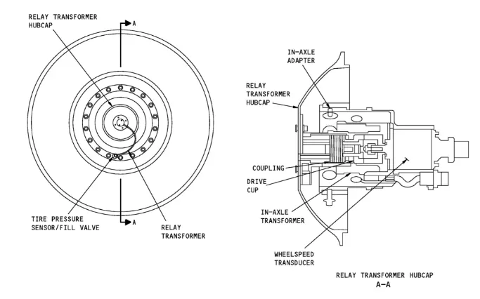
-
The tire pressure sensor/fill valve is made of an air fill valve and three independent pressure sensing channels which provide accurate tire pressure.
-
The tire pressure sensor/fill valve is installed in the wheel.
-
A relay transformer hubcap assembly connects to the tire pressure sensor/fill valve. The left 28V DC MAIN bus supplies the electrical power to operate the tire pressure indication system.
Source link:-https://www.airliners.net/
(5).Brake forces when landing. :-
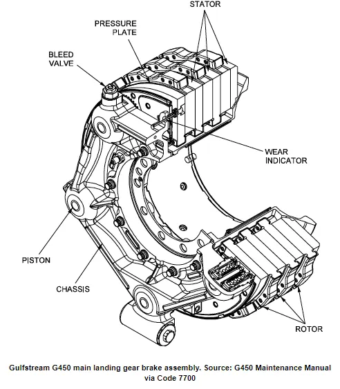
- Aircraft brakes stop a moving aircraft by converting its kinetic energy to heat energy by means of friction between rotating and stationary discs located in brake assemblies in the wheels
- On other aircraft types, the brake units are powered by the hydraulics system.
- An electrical signal is sent from the flight deck to hydraulic actuators near the main landing gear.
- Here, hydraulic fluid at 3,000 pound per square inch is used to force the brake unit against the wheel, thus slowing it down.
- This system works fine, but the pipes and actuators that form this part of the hydraulic system come at a considerable weight cost.
- Extra weight means more fuel burn, which in turn increases costs and carbon emissions.
- Brakes provide this critical stopping function during landings to enable airplanes to stop within the length of the runway.
- The most common type of brake used on aircraft is the disc brake. Disc brakes function by exploiting friction between rotating and stationary discs inside the brake.
Below image shows the assemble of brake
Brake cooling:-
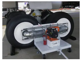
The large amount of heat generated during aircraft braking is dissipated by means of passive or active cooling. Passive cooling occurs due to natural conduction of heat through the disc material and to surrounding components, radiation of heat off the brake and wheel assembly, and convection as air flows past and through the brake assembly.
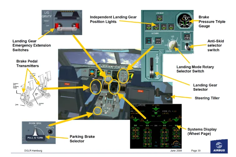
The control panel of Autobrakes is shown below:-
------------------------------------------------------------------------------------------------------------------------------------------------
Study6:-With necessary assumptions, calculate the force and power required to push / pull an aircraft by a towing vehicle.
The Solution for force and power required to push / pull an aircraft by a towing vehicle is given below:-
It mainly solves the plane bring moved by tow
- Rolling Resistance force on the aircraft (Fr1)
- Drag force on the aircraft (Fd1)
- Rolling Resistance force on tug machine (Fr2)
- Drag force on tug machine (Fd2)
- Mass of the aircraft (m1)=80,000kg (MDTOW for Boeing 737-800)
- Mass of towing machine (m2) = 50000 kg
- Coefficient of the rolling resistance for aircraft (μ1)=0.02
- Coefficient of the rolling resistance for tug (μ2)=0.03
- Drag coefficient of the aircraft (cd1) = 0.15
- Drag coefficient of the tug (cd2) = 0.7
- frontal area of the aircraft (A2) = 20 ㎡
- frontal area of the tug (A1) = 4 ㎡
- Towing speed (v) = 3 m/s
- Air density ( ρ) = 1.25 kg/m³
- Gravitational acceleration (g) = 9.81 m/s²
Calculation:-
Mathematical expression for Rolling Resistance force = `F_(rr)=mu*m*g`
Drag force `F_(d) = 1/2*ρ*A*Cd*V^2`
`F_(r1)=mu_1*m_1*g_1=0.02*80000*9.81=15696 N`
`F_(r2)=mu_2*m_2*g_2=0.03*50000*9.81=14715 N`
`F_(d1)=1/2*ρ*C_(d1)*v^2=1/2*1.25*20*0.015*3^2=16.87 N`
`F_(d2)=1/2*ρ*C_(d2)*v^2=1/2*1.25*4*0.7*3^2=15.75 N`
TOTAL FRICTIONAL LOSSES = `F_(r1)*F_(r2)*F_(d1)*F_(d2)`
=`15696+14715+16.87+15.75`
TOTAL FRICTIONAL LOSSES = `30.44 KN`
POWER REQUIRED= (TOTAL FRICTIONAL LOSSES)*(TOWING VELOCITY)
= 30.44*3
POWER REQUIRED =91.32 KW
The force required to push / pull an aircraft by a towing vehicle is `30.44 KN`
The power required to push / pull an aircraft by a towing vehicle is 91.32 KW
----------------------------------------------------------------------------------------------------------------------------------------------
Study7:-Design an electric powertrain with a type of motor, it’s power rating, and energy requirement to fulfill aircraft towing application. Estimate the duty cycle range to control the aircraft speed from zero to highest. Make all required assumptions. Prepare a table of assumed parameters. Draw a block diagram of powertrain.
- Motor
- The Induction motor is preferred over BLDC motor for a high KW range due to its operations
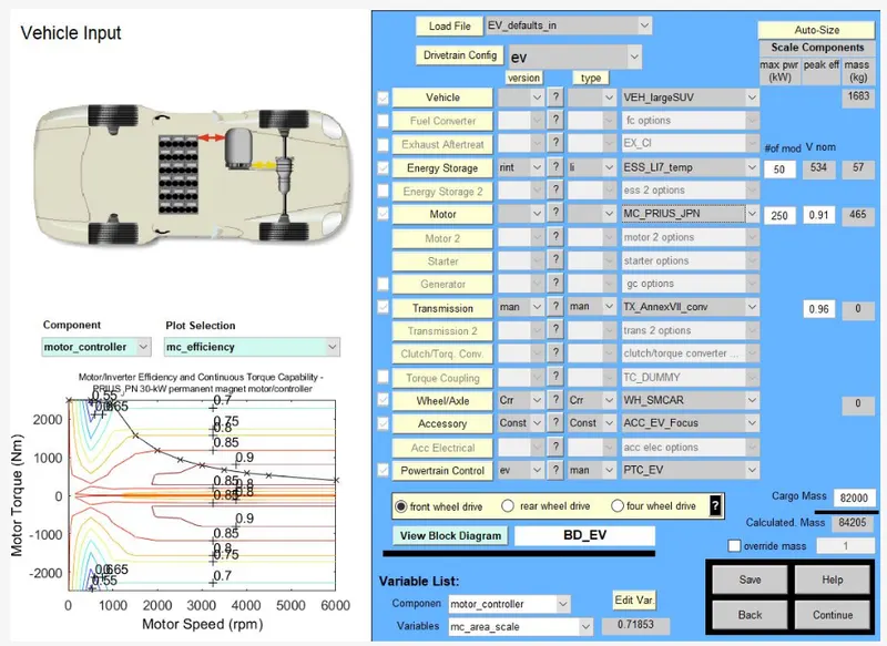
2.Power Rating:-
- The power required by motor is 91.33 KW
- Motor Efficiency = 90%
- Motor Designed to Run = 80%
- Power motor choosen for aircraft = 250 KW (As shown Above)
Power Rating = 250 KW
3.Energy Required for aircraft
- Mass of the vehicle = 84205 kg
- Energy = `P*T`
Where
- P = motor power(kw)
- T = Taxing Time(s)
- The average time for an aircraft is 10 minutes i.ee 600 sec
E = P * T
= 30.44*600
= 18,264 mj
Energy Required for vehicle = 18,264 MJ
4.DUTY CYCLE
- Motor power is 250 kw
- Full load current is 420 A
- Full Voltage 400 V
- `P_i=Li*Vo`
- `Vi = 250/420`
- `Pout=Lout*Vout`
- The current at i/p and o/p are same.so ratio power at i/p and o/p is equal to voltage
- `P_(o/p)/P_(i/p)=V_o/V_i`
- `30.44/250=0.1276%`
Duty cycle from 0 to 121.76% is shown
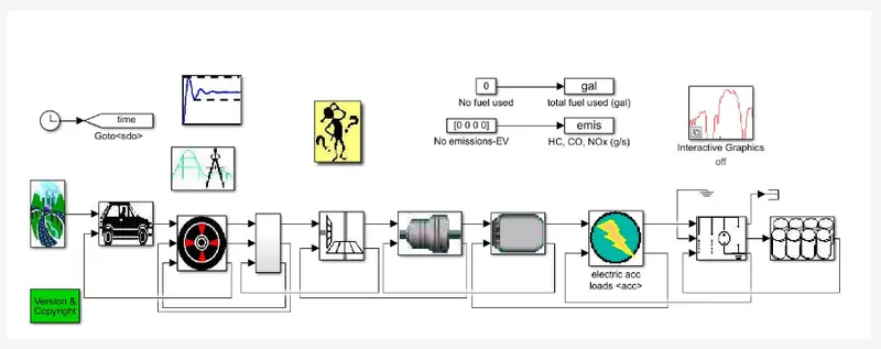
5.Block Diagram