Week -2
Aim:
- To make Make a Simulink model of Doorbell using solenoid block
- To Use a thermistor to sense the temperature of a heater & turn on or turn off the fan
Question 1:-
Theory:-
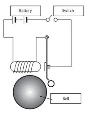
The doorbell works on the principle of electromagnetism. It uses a Solenoid. When the Switch is in Closed Condition, Electricity is passed into the Solenoid which creates an Electromagnetic field. The plunger moves due to this electromagnetic field and hits the bell to produce a sound.
Simulink Model:
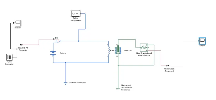
Blocks Used:-
- Pulse generator:-A pulse generator is either an electronic circuit or a piece of electronic test equipment used to generate rectangular pulses. Pulse generators are used primarily for working with digital circuits, related function generators are used primarily for analog circuits.
- Simulink-ps converter:- converts the input Simulink® signal into a physical signal.
- Switch:-A switch is an electrical component that can disconnect or connect the conducting path in an electrical circuit, interrupting the electric current or diverting it from one conductor to another.
- Battery:-It provides Voltage to the system
- Solenoid:-This block implements the electrical and mechanical characteristics of a solenoid.
- Mechanical and Electrical reference:-This block represents a mechanical translational reference point, that is, a frame or a ground. Use it to connect mechanical translational ports that are rigidly affixed to the frame (ground).
- Ideal Translation Motion Sensor:-This block measures velocity or displacement in a mechanical translational network. The sensor is ideal since it does not account for inertia, friction, delays, energy consumption, and so on.
- scope:- To view the characteristics of a property with respect to Time(Simulation Time)
Condition:- Create a situation where the switch is closed for 2 seconds and then released. Observe the physical movement of the plunger.
Result1:-
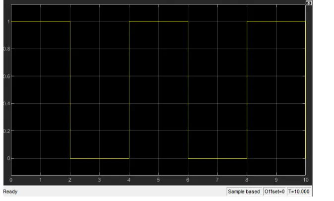
This is the Result obtained for 10 seconds of the given simulation.
For every interval of 2 Seconds the switch is turned off, Hence the waveform is Obtained.
Result2:-
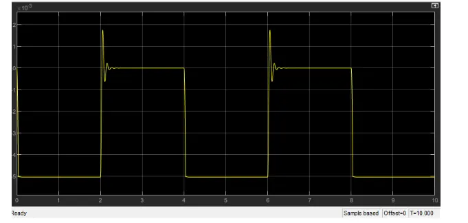
The Above result is Obtained for Time period 2 seconds.
Question 2:- Use a thermistor to sense the temperature of a heater & turn on or turn off the fan
Thermistor
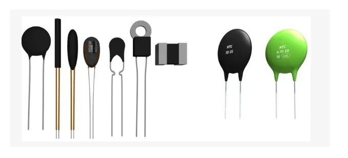
A thermistor is a resistance thermometer, or a resistor whose resistance is dependent on temperature. The term is a combination of “thermal” and “resistor”. It is made of metallic oxides, pressed into a bead, disk, or cylindrical shape and then encapsulated with an impermeable material such as epoxy or glass.
There are two types of thermistors: Negative Temperature Coefficient (NTC) and Positive Temperature Coefficient (PTC). With an NTC thermistor, when the temperature increases, resistance decreases. Conversely, when temperature decreases, resistance increases. This type of thermistor is used the most.
A PTC thermistor works a little differently. When temperature increases, the resistance increases, and when temperature decreases, resistance decreases. This type of thermistor is generally used as a fuse.
Input Temperatures:-
T = 20 °C from 0 to 10 seconds,
T = 27 °C from 10 to 30 seconds
T = 23 °C from 30 to 50 seconds
Fan Condition:-
ON if the temperature above 25 °C
OFF otherwise
For Fan Operations Using Thermistor:-
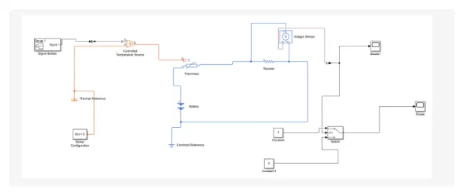
Here the input is fed through the block ‘Signal Builder’. The input data is given Based on initial conditions provided in the challenge.

As per the above mentioned conditions, the input of signal builder is incorporated as shown below,
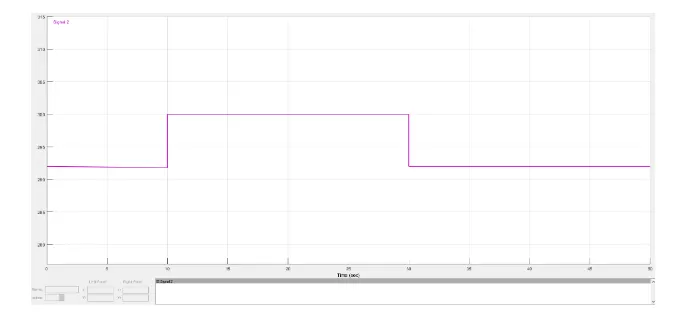
Before this signal is been fed into the controlled temperature source the settings of the ‘Simulink physical signal converter’ have to be modified . In the input handling,the filter input and derivative has to be selected instead of signals this is because here we use two heat source namely “controlled temperature source” (the ideal energy source in a thermal network that can maintain a controlled temperature difference regardless of the hear flow rate)
The positive side of the thermistor is connected to the positive terminal of the battery and negative side of the terminal is connected to the current sensor (which helps to detect the current flow in the circuit) This is followed by electrical resistance.
The Valve from the current sensor is converted into the Simulink signal using the converter. The Valve obtained is displayed in the display block. This just to give the threshold valve inside the switch,which has 2 outputs based on 2 conditions if the valve is above the threshold valve of output will be 1 and f the valve is below the threshold valve of the output will be 0. The final Output is recorded in the scope.
Output:-
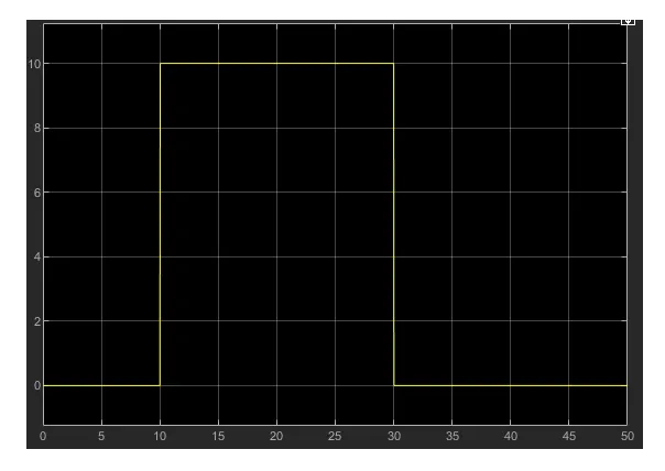
So based on the given conditions the fan should work only in the time period of 10 to 30 seconds which is exactly depicted in the graph shown above
CONCLUSION:-
1. Thus, both the objectives were achieved successfully.
2. similar approach can be used for simulating other physical devices using simulink.