Project-1: Modelling an electric Car with Li-ion battery
Create a MATLAB model of electric car which uses lithium ion battery and suitable motor. Choose suitable blocks from Simscape or Powertrain block set. Implement the vehicle speed control using PI controller and generate brake and accelerator commands. Avoid using readymade driver block for speed control.
Prepare a report about your model including following:
Objectives, System level configurations, Model parameters, Results, Conclusion.
(Note- The simulink model file should be compulsorily attached).
Aim of the project: Creating a MATLAB model of an electric car that uses a lithium-ion battery and a suitable motor by Choosing suitable blocks from Simscape or Powertrain block set.
Implementing the vehicle speed control using the PI controller and generating brake and accelerator commands. Avoid using readymade driver blocks for speed control.
Specifications and Design:
Electrical Vehicles are rapidly replacing conventional ICE vehicles across the globe. But selecting the right architecture and components is a difficult task because of the options available in today’s time. A vehicle is basically an electromechanical system with a large number of subsystems. The close integration of all the sub-systems is essential for deriving the most out of it and making it more efficient. Testing all the combination physically is neither practically feasible nor possible. So, a simulating tool is essential to evaluate important parameters such as range, acceleration, power, and cost of the system in order to compare and validate the design.
MATLAB Simulink is a powerful tool that lets you design and validates your system. This feature-laden software with its computing prowess is a good software to accelerate our design phase. In this project, we will see how we can use MATLAB to design an EV power train. We will be utilizing generic parameters for a vehicle.
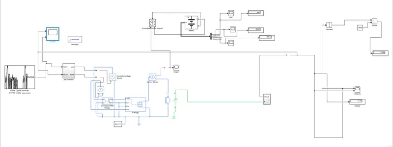
**SIMULINK file is attached with this project**
1. Vehicle Body Subsystem:
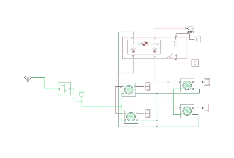
This subsystem consist of :
a) Fixed Gear:
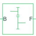
- The Simple Gear block represents a gearbox that constrains the connected driveline axes of the base gear, B, and the follower gear, F, to corotate with a fixed ratio that is specified.
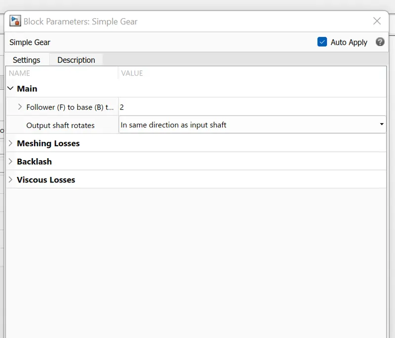
- Inertia:

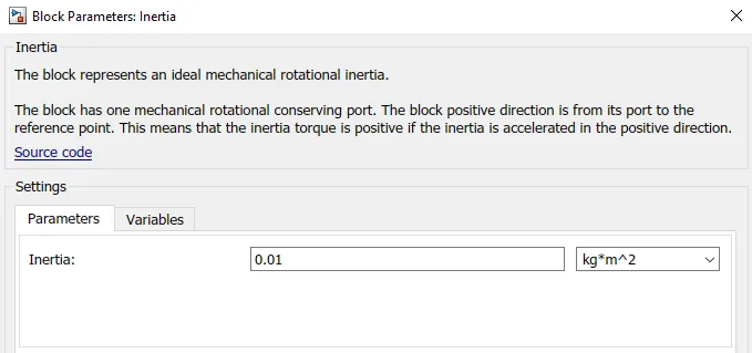
- The Inertia block represents an ideal mechanical rotational inertia.
- Tire (Magic Formula):
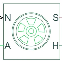
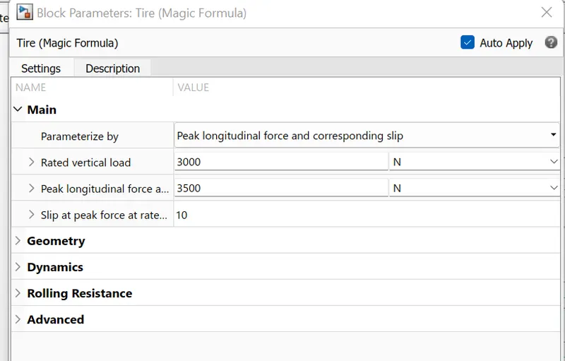
- The Tire (Magic Formula) block models a tire with longitudinal behavior given by the Magic Formula an empirical equation based on four fitting coefficients. The block can model tire dynamics under constant or variable pavement conditions.
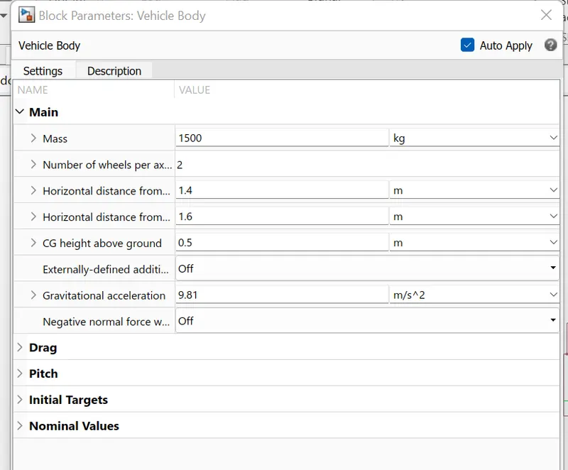
c)Vehicle body:
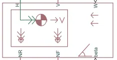
- The Vehicle Body block represents a two-axle vehicle body in longitudinal motion. The vehicle can have the same or a different number of wheels on each axle. For example, two wheels on the front axle and one wheel on the rear axle. The vehicle wheels are assumed identical in size. The vehicle can also have a center of gravity (CG) that is at or below the plane of travel.
- The block accounts for body mass, aerodynamic drag, road incline, and weight distribution between axles due to acceleration and road profile. Optionally include pitch and suspension dynamics. The vehicle does not move vertically relative to the ground.
- The block has the option to include an externally-defined mass and an externally-defined inertia. The mass, inertia, and center of gravity of the vehicle body can vary over the course of simulation in response to system change
2. PID CONTROL SUBSYSTEM:
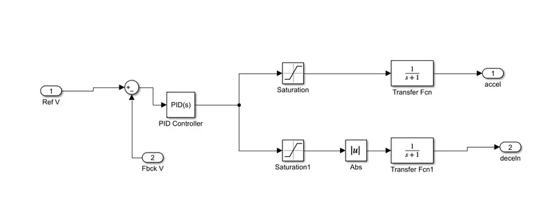
It consist of :
a) Sum Block:
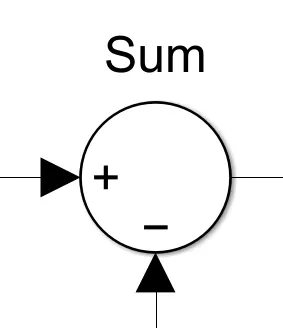
This block subtracts feedback velocity from reference velocity.
This output is given to PID controller.
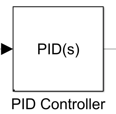
b)PID Controller:
Parameters:
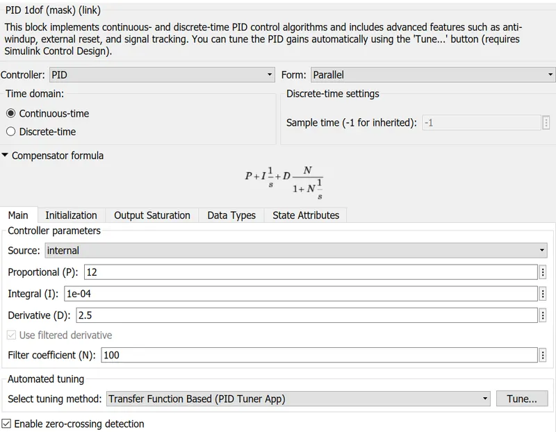
The output from the sum block is given to this block.
based on the PID, the output is generated.
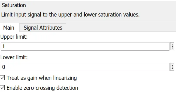
c)Saturation Block:
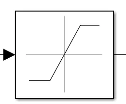
Parameters:
Acceleration:
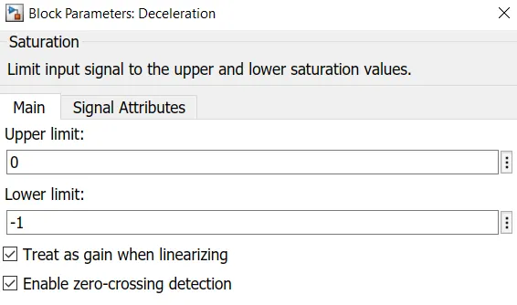
Deceleration:
3. Controlled Voltage Source:
This block helps to limit the output signal from PID controller and separate deceleration and acceleration values.
-
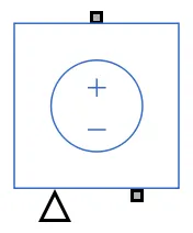
The Controlled Voltage Source block represents an ideal voltage source that is powerful enough to maintain the specified voltage at its output regardless of the current flowing through the source.
-
The output voltage is V = Vs, where Vs is the numerical value presented at the physical signal port.
- 4.Controlled PWM Voltage:
-
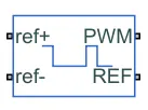
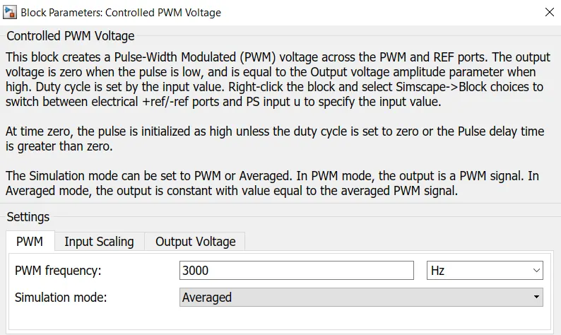
- The Controlled PWM Voltage block represents a pulse-width modulated (PWM) voltage source. The block has two modeling variants,
-
Electrical input ports — The block calculates the duty cycle based on the reference voltage across its ref+ and ref- ports. This modeling variant is the default.
-
PS input — Specify the duty cycle value directly by using an input physical signal port.
-
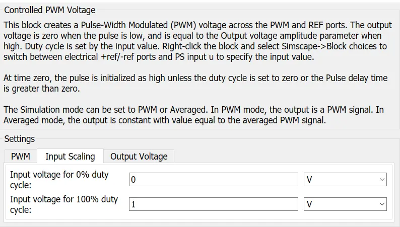
For the Electrical input ports variant of the block, the demanded duty cycle is
100∗Vref−VminVmax−Vmin%100∗Vref−VminVmax−Vmin %
where:
-
Vref is the reference voltage across the ref+ and ref- ports.
-
Vmin is the minimum reference voltage.
-
Vmax is the maximum reference voltage.
-
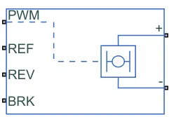
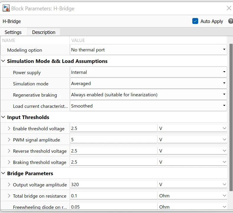
- 5.H-Bridge:
-
This block is used to change the polarity of the voltage applied across the DC motor so as to run the motor in forward and reverse direction as per the input command.
-
The output from these blocks is sent to a transfer function then these are provided to motor controller block.
- 6. Current Sensor:
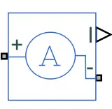
- This block is used to measure the flow of current through a circuit
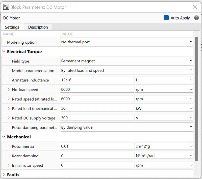
- 7.DC motor:
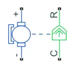
- To convert the electrical energy to mechanical energy we use motors. In this electric vehicle model, we have used DC motor. This motor can act as a generator also in case of regenerative braking.
- 8.Controlled Current Source:
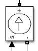
- The Controlled Current Source block converts the Simulink input signal into an equivalent current source. The generated current is driven by the input signal of the block.
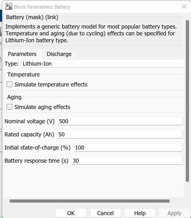
- 9. Li-ion battery:
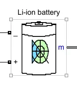
- The Battery block implements a generic dynamic model that represents most popular types of rechargeable batteries.
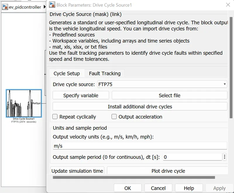
10. Drive Cycle :
It generates a standard drive cycle, this blocks output is the vehicle's longitudinal speed
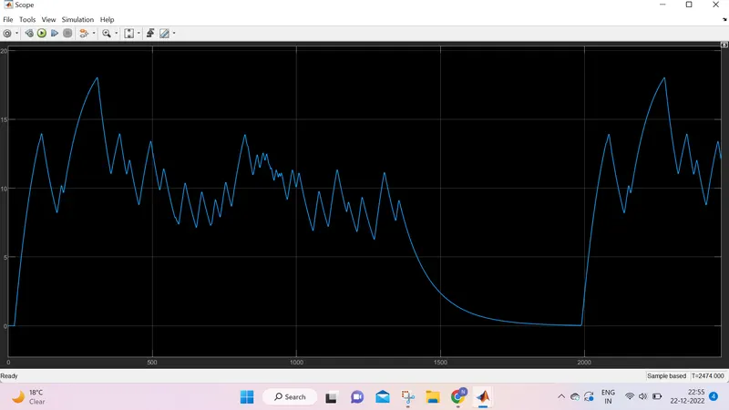
RESULT GRAPH:
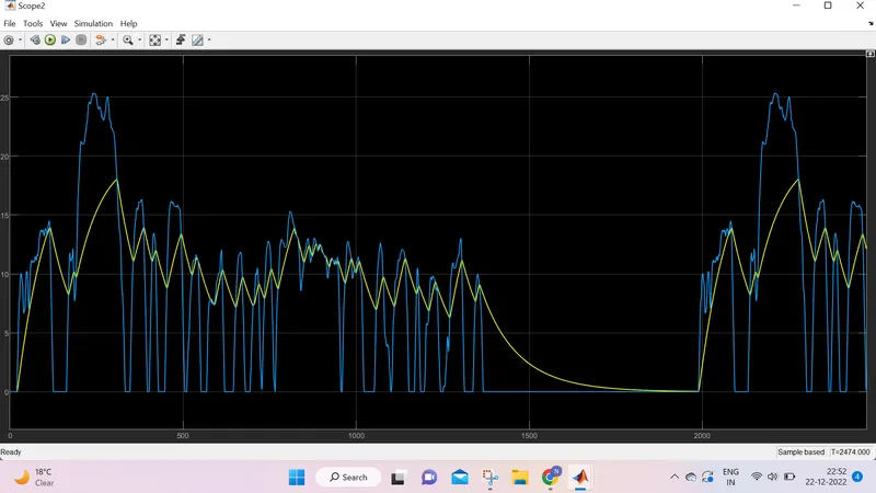
1. feedback velocity and drive cycle
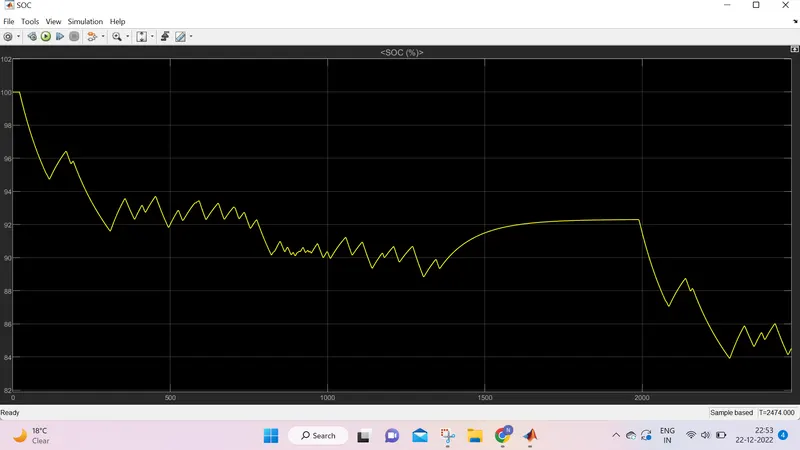
2.SOC
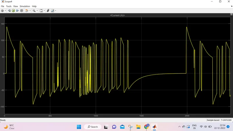
3. CURRENT
CONCLUSION:
- In the speed trace plots for drive cycles that are observed in this study, the feedback speed plot and the reference speed plot almost overlap each other but there are regions where both the speeds are different. It is when the vehicle is decelerating.
The reference speed plot falls sharply but the feedback speed does not. This is due to the inertia of the vehicle body. As the inertia of the vehicle body is higher, it takes a longer duration for it to decelerate.
That is why the overlapping is not 100%. - The battery's state of charge for each drive cycle can be visualized from the SOC plot. As long as the vehicle is accelerating the SOC is decreasing but as soon as the deceleration starts, the SOC plot goes slightly up. This is because the battery is being charged, due to regenerative braking during deceleration.
REFERENCE: