Project-1: Modelling an electric Car with Li-ion battery
Electric vehicles have low running costs as they have fewer moving parts for maintenance and are also very environmentally friendly as they use little or no fossil fuels (petrol or diesel). While some EVs used lead-acid or nickel-metal hydride batteries, the standard for modern battery electric vehicles is now considered to be lithium-ion batteries a s they have greater longevity and are excellent at retaining energy, with a self-discharge rate of just 5% per month.
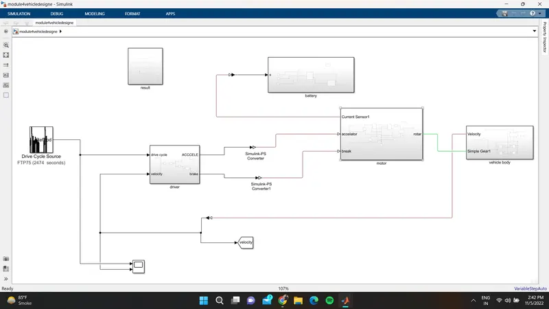
a MATLAB model of an electric car which uses a lithium-ion battery and a suitable motor. Choose suitable blocks from Simscape or Powertrain block set. Implement the vehicle speed control using PI controller and generate brake and accelerator commands
PID controller subsystem:............................................
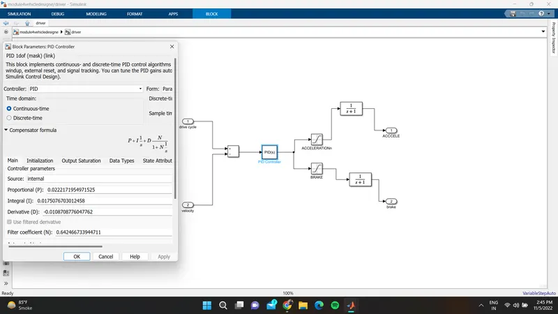
in this, we have used add block which:--
subtracts feedback velocity from reference velocity.
This output is given to the PID controller.
PID Controller:
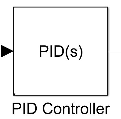
the parameter of the PID controller has been shown in the above screenshot of PID COntroller
we have used SATURATION BLOCK :
one for acceleration
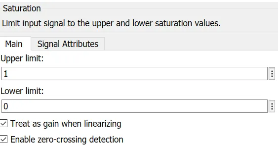
and one we have used for brake/deacceleration
in this, the upper value has been given to 0 and the lower value to be -2
These block helps to limit the output signal from the PID controller and separate deceleration and acceleration values.
The output from these blocks is sent to a transfer function then these are provided to the motor controller block.
Motor Controller Subsystem:
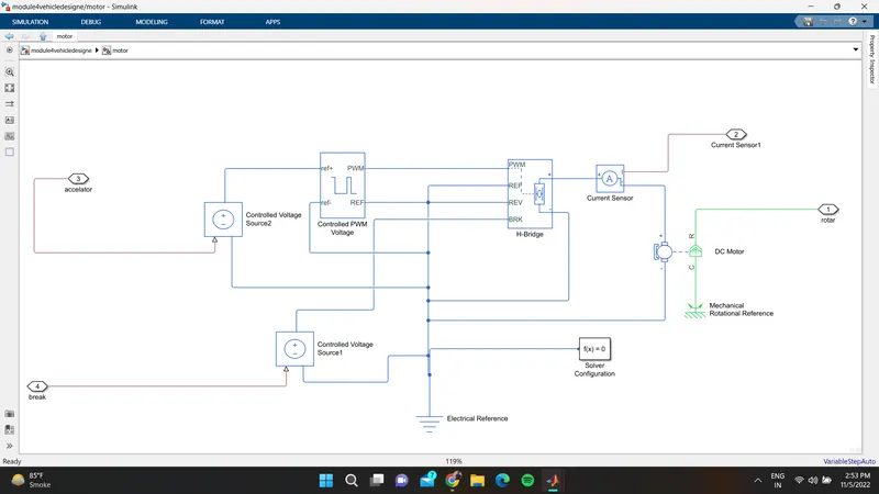
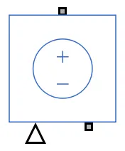
- Controlled Voltage Source:
-
The Controlled Voltage Source block represents an ideal voltage source that is powerful enough to maintain the specified voltage at its output regardless of the current flowing through the source.
-
The output voltage is V = Vs, where Vs is the numerical value presented at the physical signal port
- Controlled PWM Voltage:
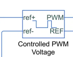
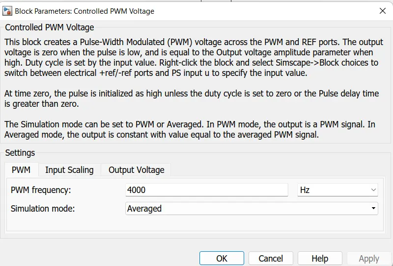
It is used to give the Pulse Width Modulation signals to the H bridge circuit at the PWM terminal. The +ve reference terminal of the block is connected to the controlled voltage source and -ve is connected to the electrical reference, the PWM is connected to the H bridge PWM as said above and REF is connected to the REF and REV terminals of the H bridge.
H - Bridge :
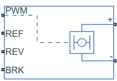
As the name indicates that the H symbol in the block is connected to the DC motor and the PWM, REF, REV, and BRK are used to control the block DC motor.
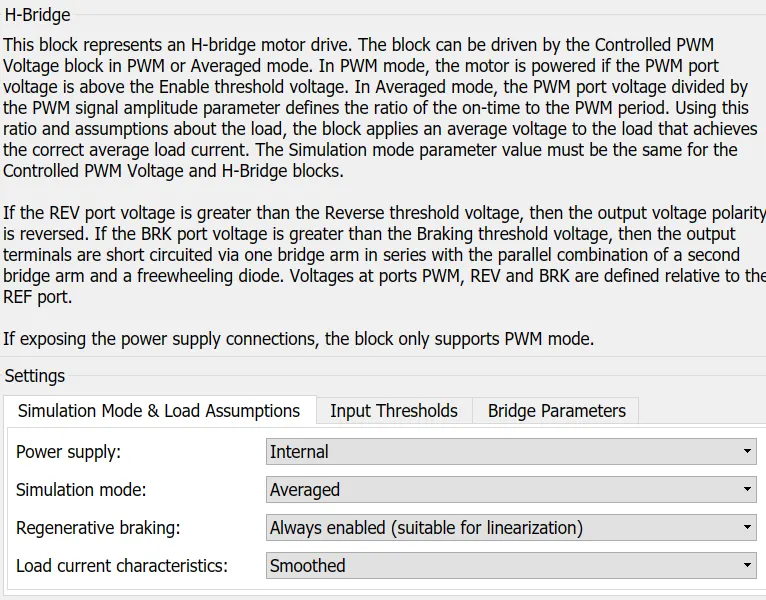
in the input threshold, the valve for voltage is 50v provided
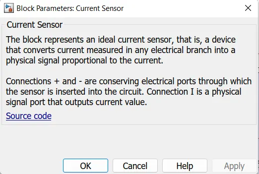
current sensor:-------
Electrical reference:
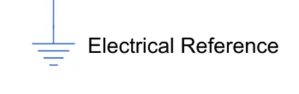
It is used to connect all the terminals of the negative signals and the reference values as the ground.
Ps-Simulink converter:
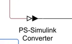
It is used to connect the line from the physical signal to Simulink which act as a converter.
DC Motor :
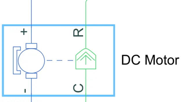
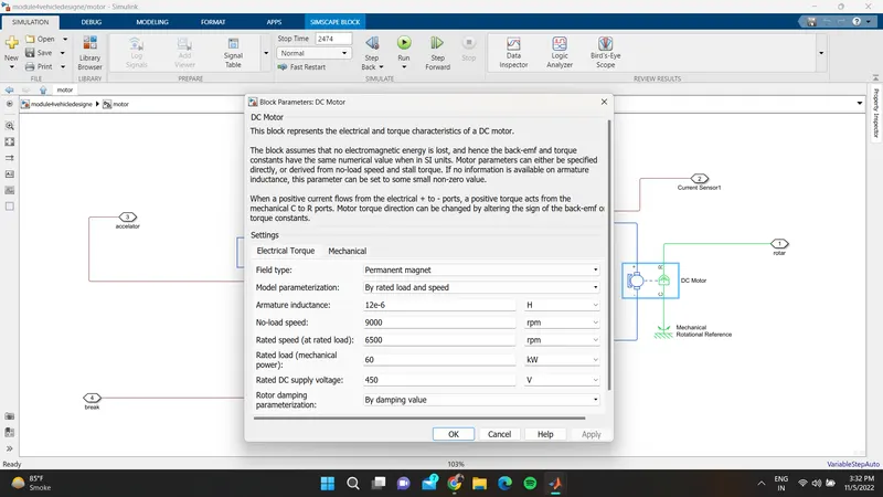
It is used to convert electrical energy to mechanical energy. In this electric vehicle model, we have used a type is permanent magnet DC motor. This motor can also act as a generator in the case of regenerative braking.
In this block, the motor's electrical side is represented with the blue color and the mechanical side is represented with green as well with the combination of shafts which is in the dotted line. here the motors +ve and -ve terminals are connected to the H-Bridge +ve and -ve terminals respectively with the electrical reference in the -ve side.
Mechanical rotational reference:
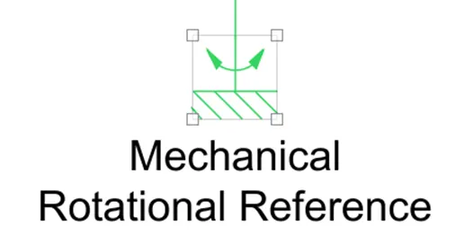
It is represented as a mechanical ground reference point that is as a frame part that is used to connect rotational parts to the ground.
Vehicle Body :
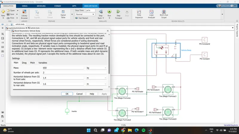
simple gear
Connections B (base) and F (follower) are mechanical rotational conserving ports. Specify the relation between base and follower rotation directions with the Output shaft rotates parameter
4 - Tyre :
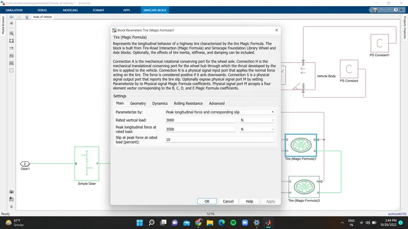
Connection A is the mechanical rotational conserving port for the wheel axle
Connection N is a physical signal input port that applies the normal force acting on the tire
Connection S is a physical signal output port that reports the tire slip.
vehicle body:------------
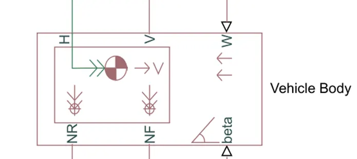
- Connections V, NF, and NR are physical signal output ports for vehicle velocity and front and rear normal wheel forces, respectively. Wheel forces are considered positive if acting downwards.
- Connections W and beta are physical signal input ports corresponding to headwind speed and road inclination angle, respectively.
Battery :
In this subsystem we have used a battery block, a controlled current source block bus selector and Import and outport blocks.
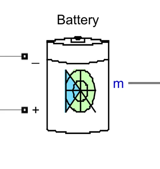 the voltage supplied to the battery pack is about 450v
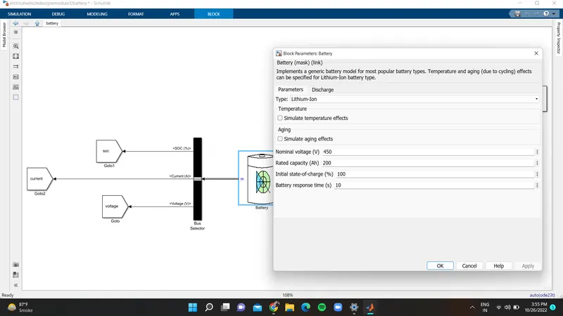
We can say that the battery is one of the main important parts or the block in the vehicle and model as well. By connecting this terminal to the controlled voltage source it supplies controlled signals to discharge and also charging in the regenerative type as well.
Bus Selector :
The bus selector is used to block the output signals which are given as an input to that bus
powergui
It is used for the analysis and measurement of parameters like voltage, current, active power, reactive power like that.
Solver configuration:
It is placed in the power control unit for the mathematical values in the model solver settings at the simulation time
To get the results of this model we have to keep the stop time to 2474 sec or above because of the given drive cycle source with FTP (2474 seconds)
.
.
.
.
..
RESULT......................................................................
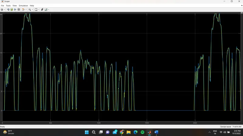
It is the combination of both the drive cycle and the vehicle body velocity which is called a feedback reference. Here the yellow represents the velocity and the blue is for the drive cycle source. They both are looks in similar lines with different values. The changes of the values of this give the acceleration and the deceleration values from the PID. Here if we observe that in the given graph in both values are changes in change in the accel and dec values but in the constant time they both are in the same
- When the velocity and the drive cycle data can equally merged and the vehicle can control with respect the drive cycle FTP-75
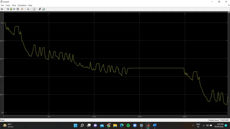
SOC (%) :
It reduces based on the given input to the battery through the current signals
Voltage (V) :
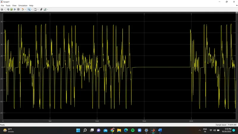
Battery current:
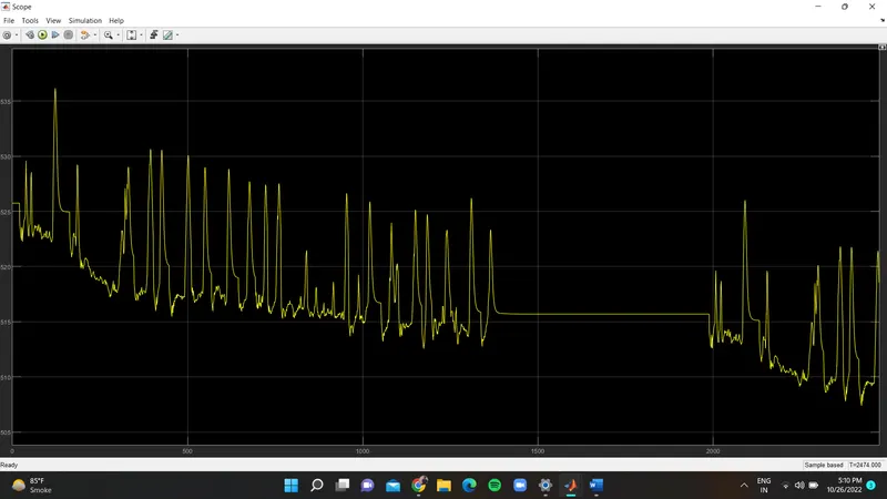
if we observe here that acceleration goes up its current values increased and in it decelerates it value is reduced respectively as above at the constant time that is from the near value of 1400 to 2000 sec time it gets decreased slightly due to losses.