Project-1: Modelling an electric Car with Li-ion battery
MODELING AN ELECTRIC CAR WITH LI ION BATTERY
AIM
Create a detailed MATLAB model of an electric car.
OBJECTIVE
Create a MATLAB model of an electric car that uses a lithium-ion battery and a suitable motor. Choose suitable blocks from Simscape or Powertrain block set. Implement the vehicle speed control using PI controller and generate brake and accelerator commands. Avoid using a ready-made driver block for speed control.
INTRODUCTION
The age of the electric car is upon us. Earlier this year, the US automobile giant General Motors announced that it aims to stop selling petrol-powered and diesel models by 2035. Audi, based in Germany, plans to stop producing such vehicles by 2033. Many other automotive multinationals have issued similar road maps. Suddenly, major carmakers foot-dragging on electrifying their fleets is turning into a rush for the exit.
The electrification of personal mobility is picking up speed in a way that even its most ardent proponents might not have dreamt of just a few years ago. In many countries, government mandates will accelerate change. But even without new policies or regulations, half of global passenger-vehicle sales in 2035 will be electric, according to the BloombergNEF (BNEF) consultancy in London.
This massive industrial conversion marks a “shift from a fuel-intensive to a material-intensive energy system”, declared the International Energy Agency (IEA) in May. In the coming decades, hundreds of millions of vehicles will hit the roads, carrying massive batteries inside them . And each of those batteries will contain tens of kilograms of materials that have yet to be mined.
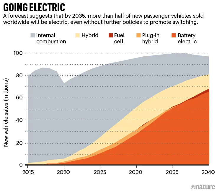
Anticipating a world dominated by electric vehicles, materials scientists are working on two big challenges. One is how to cut down on the metals in batteries that are scarce, expensive, or problematic because their mining carries harsh environmental and social costs. Another is to improve battery recycling, so that the valuable metals in spent car batteries can be efficiently reused. “Recycling will play a key role in the mix,” says Kwasi Ampofo, a mining engineer who is the lead analyst on metals and mining at BNEF.
Battery- and carmakers are already spending billions of dollars on reducing the costs of manufacturing and recycling electric-vehicle (EV) batteries — spurred in part by government incentives and the expectation of forthcoming regulations. National research funders have also founded centres to study better ways to make and recycle batteries. Because it is still less expensive, in most instances, to mine metals than to recycle them, a key goal is to develop processes to recover valuable metals cheaply enough to compete with freshly mined ones. “The biggest talker is money,” says Jeffrey Spangenberger, a chemical engineer at Argonne National Laboratory in Lemont, Illinois, who manages a US federally funded lithium-ion battery-recycling initiative, called ReCell.
Future of lithium
The first challenge for researchers is to reduce the amounts of metals that need to be mined for EV batteries. Amounts vary depending on the battery type and model of vehicle, but a single car lithium-ion battery pack (of a type known as NMC532) could contain around 8 kg of lithium, 35 kg of nickel, 20 kg of manganese and 14 kg of cobalt, according to figures from Argonne National Laboratory.
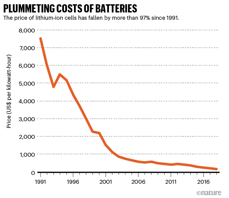
Analysts don’t anticipate a move away from lithium-ion batteries any time soon: their cost has plummeted so dramatically that they are likely to be the dominant technology for the foreseeable future. They are now 30 times cheaper than when they first entered the market as small, portable batteries in the early 1990s, even as their performance has improved. BNEF projects that the cost of a lithium-ion EV battery pack will fall below US$100 per kilowatt-hour by 2023, or roughly 20% lower than today (see ‘Plummeting costs of batteries’). As a result, electric cars — which are still more expensive than conventional ones — should reach price parity by the mid-2020s. (By some estimates, electric cars are already cheaper than petrol vehicles over their lifetimes, thanks to being less expensive to power and maintain.)
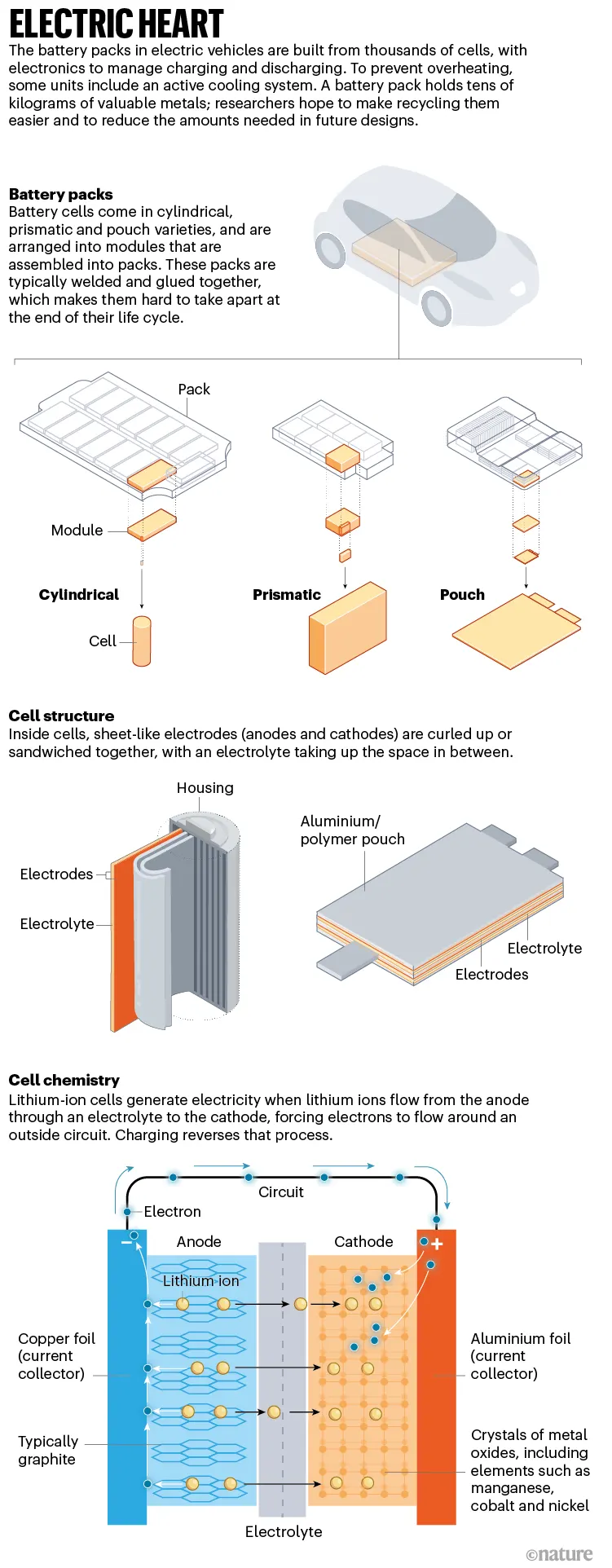
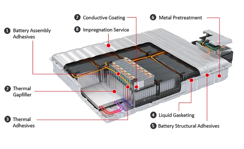
- Most electric vehicles use lithium-ion batteries (Li-Ions or LIBs). Lithium-ion batteries have a higher energy density, longer life span and higher power density than most other practical batteries. Complicating factors include safety, durability, thermal breakdown and cost. Li-ion batteries should be used within the safe temperature and voltage ranges in order to operate safely and efficiently.
- Increasing the battery's lifespan decreases effective costs. One technique is to operate a subset of the battery cells at a time and switching these subsets.
- In the past, nickel-metal hydride battery batteries were used in some electric cars, such as those made by General Motors. These battery types are considered outdated due to their tendencies to self-discharge in the heat. Furthermore, a patent for this type of battery was held by Chevron, which created a problem for their widespread development. These factors, coupled with their high cost, have led to lithium-ion batteries leading as the predominant battery for EVs.
- The prices of lithium-ion batteries are constantly decreasing, contributing to a reduction in the price of electric vehicles.
Electrical Motor:
- The power of a vehicle's electric motor, as in other machines, is measured in kilowatts (kW). Electric motors can deliver their maximum torque over a wide RPM range.
- This means that the performance of a vehicle with a 100 kW electric motor exceeds that of a vehicle with a 100 kW internal combustion engine, which can only deliver its maximum torque within a limited range of engine speed.
- The efficiency of charging varies considerably depending on the type of charger, and energy is lost during the process of converting the electrical energy to mechanical energy.
- Usually, direct current (DC) electricity is fed into a DC/AC inverter where it is converted to alternating current (AC) electricity and this AC electricity is connected to a 3-phase AC motor.
- For electric trains, forklift trucks, and some electric cars, DC motors are often used. In some cases, universal motors are used, and then AC or DC may be employed. In recent production vehicles, various motor types have been implemented; for instance, induction motors within Tesla Motor vehicles and permanent magnet machines in the Nissan Leaf and Chevrolet Bolt
Motor Controller:
- The motor controller of an electric car administers its complete operation and the distribution of its power at any given moment. It acts as a floodgate between the motor and batteries.
- It helps monitor and regulates all key performance indications such as the vehicle's operator, motor, battery, and accelerator pedal. It has a microprocessor that can limit or redirect current.
- It is used to either improve the mechanical performance of the car or suit the operator's driving style. There are also more refined controllers which are capable of greater accuracy and thus, higher efficiency.
Simulation Model
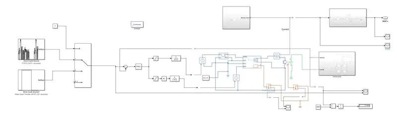
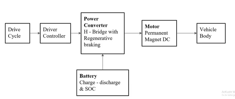
The electric vehicle is constructed in a manner of four step-by-step processes,so to design of the EV model always starts within the order:
1) construction of vehicle body design
2)Selecting the motor
3)Suitable control unit for motor
4)Source of energy for motors
Construction of vehicle body design
- Motor will produce the rotational output which will give to the vehicle body and transmission system. The rotational output is taken by the gear system here to maintain the constant speed throughout the transmission without any loss in speed from the motor to tires.
- Below is a diagram that is how it is inside the vehicle body and transmission system and in the main design, it is referred just only as a transmission system. Here I created a Rear-wheel drive transmission system.
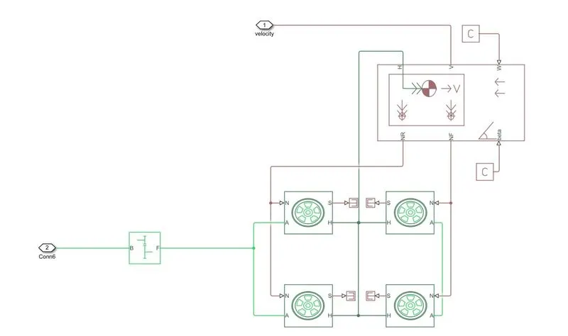
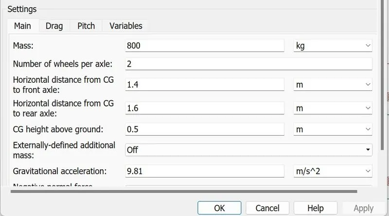
The Vehicle Body block represents a two-axle vehicle body in longitudinal motion. The vehicle can have the same or a different number of wheels on each axle. For example, two wheels on the front axle and one wheel on the rear axle. The vehicle wheels are assumed identical in size. The vehicle can also have a center of gravity (CG) that is at or below the plane of travel.
The block accounts for body mass, aerodynamic drag, road incline, and weight distribution between axles due to acceleration and road profile. Optionally include pitch and suspension dynamics. The vehicle does not move vertically relative to the ground.
The block has an option to include an externally-defined mass and an externally-defined inertia. The mass, inertia, and center of gravity of the vehicle body can vary over the course of simulation in response to system changes.
H- t is the mechanical translation converting port associated with the horizontal motion of the vehicle body
NR- Signal output port for rear normal wheel forces
NF- Signal output port for front normal wheel forces
V- Signal output port for vehicle velocity
Beta- Signal output port for road inclination angle
W- Signal output port for headwind speed
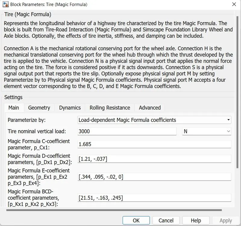
Tire ( magic frame)
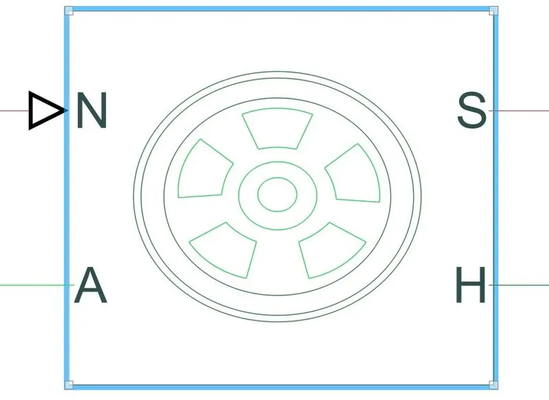
The Tire-Road Interaction (Magic Formula) block models the interaction between the tire tread and road pavement. The longitudinal force arising from this interaction is given by the magic formula, an empirical equation based on four fitting coefficients. Tire properties such as compliance and inertia are ignored.
The A ports of the tire are the mechanical rotational conserving port and receive mechanical rotational input from the gearbox which receives its input from the DC motor.
The H port of the tire is the mechanical translational conserving port for the wheel hub and is connected to the H port of the vehicle body through which the trust developed by the tire is applied to the vehicle.
Here we are not considering any slip, so an terminator block is connected to all the slip port of each tire. Also, grade angle and wind velocity are not considered.
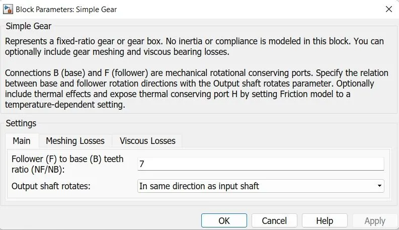
The input is received from the DC motor to the simple gear block which is then transmitted to the wheel considering the inertia couple at the output shaft.
Simple Gear
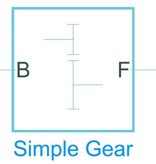
This example shows a simple gear coupling two inertias (shafts). The gear ratio between the follower (F) and base (B) is 2:1. Thus the angular velocity of the follower shaft is half the angular velocity of the base shaft. The follower shaft torque is twice the base shaft torque.
CONTROLLER MODEL
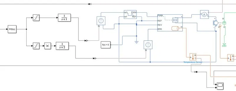
The Motor controller will get input from the longitudinal driver. Its tasks are to control the speed of the motor and drive according to the input of the driver.
- Majorly motor controlled we designed had two main parts named PWM voltage generator and H-Bridge Input 1 is getting from the acceleration of a longitudinal driver and it is given to a controlled voltage source block where it is input to the controlled PWM voltage will generate a PWM signal in such a way that H-bridge will generate the required voltage to operate the DC motor for the given driver input
- PWM voltage block negative reference and REF are grounded and REF of H bridge respectively. H-bridge is a motor controller that has IGBT components aligned in the shape of H and will operate only two at a time respectively to the input of the signal from the PWM block.
- When deceleration occurs this H-bridge will give an output from the positive and negative terminals of it. These negative & positive terminals are later connected to the DC motor and battery. All these components are the simscape electrical components so they need a connection to the solver configuration block which helps to solve the simulation.
DC MOTOR
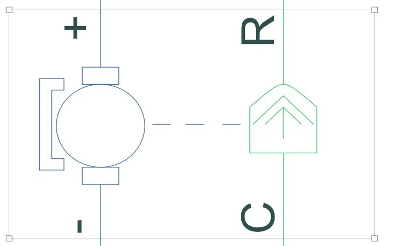
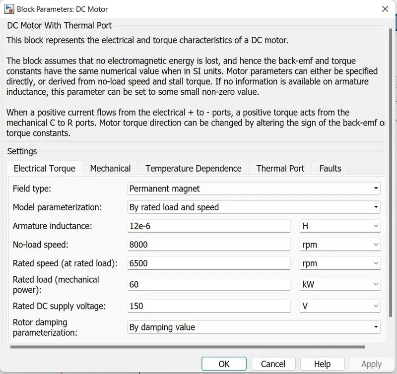
This block represents the electrical and torque characteristics of a DC motor. It assumes that no electromagnetic energy is lost, and hence the back-emf and torque constants have the same numerical value when in SI units. Motor parameters can either be specified directly, or derived from no-load speed and stall torque. If no information is available on armature inductance, this parameter can be set to some small non-zero value.
When a positive current flows from the electrical + to - ports, a positive torque acts from the mechanical C to R ports. Motor torque direction can be changed by altering the sign of the back-emf or torque constants.
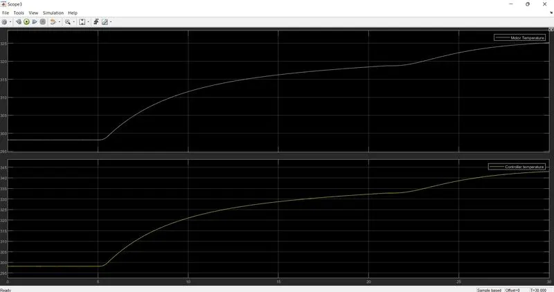
Temperature Sensor
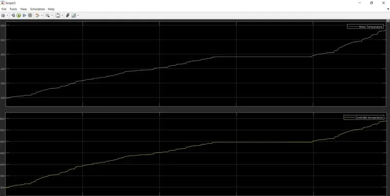
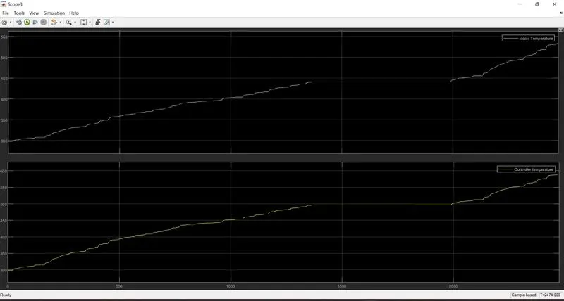
- Temperature Sensor is used to measure the temperature of the H-Bridge and Motor.
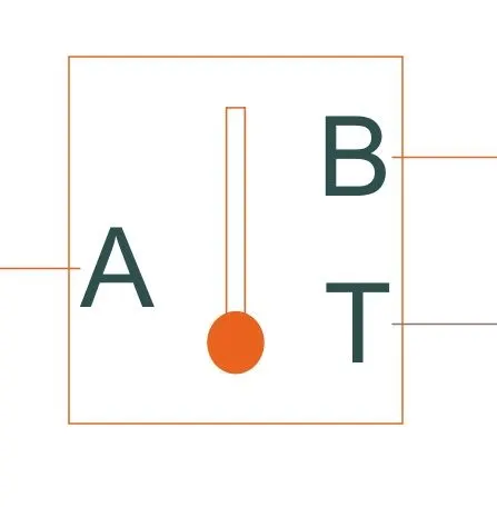
- This block measures temperature in a thermal network. There is no heat flow through the sensor. The physical signal port T reports the temperature difference across the sensor.
- The measurement is positive when the temperature at port A is greater than temperature at port B.
H BRIDGE
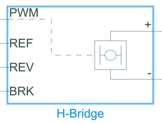
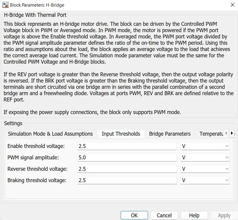
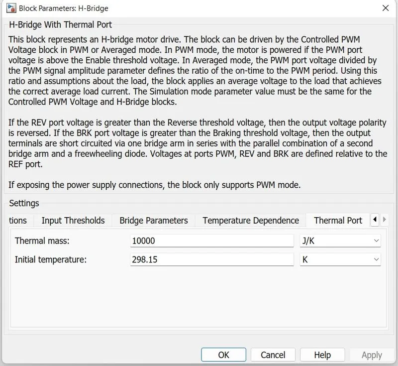
The H-Bridge block output is a controlled voltage that depends on the input signal at the PWM port. If the input signal has a value greater than the Enable threshold voltage parameter value, the H-Bridge block output is on and has a value equal to the value of the Output voltage amplitude parameter. If it has a value less than the Enable threshold voltage parameter value, the block maintains the load circuit using one of the following three Freewheeling mode options:
- Via one semiconductor switch and one freewheeling diode
- Via two freewheeling diodes
- Via two semiconductor switch and one freewheeling diode
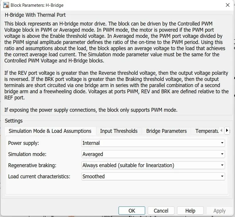
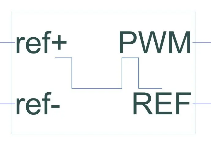
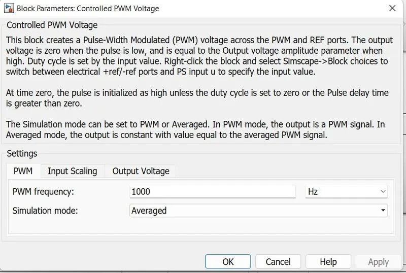
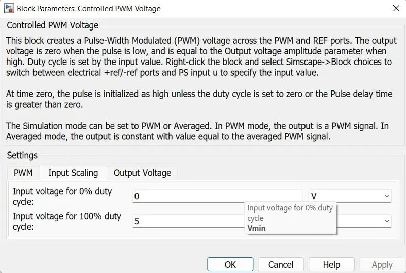
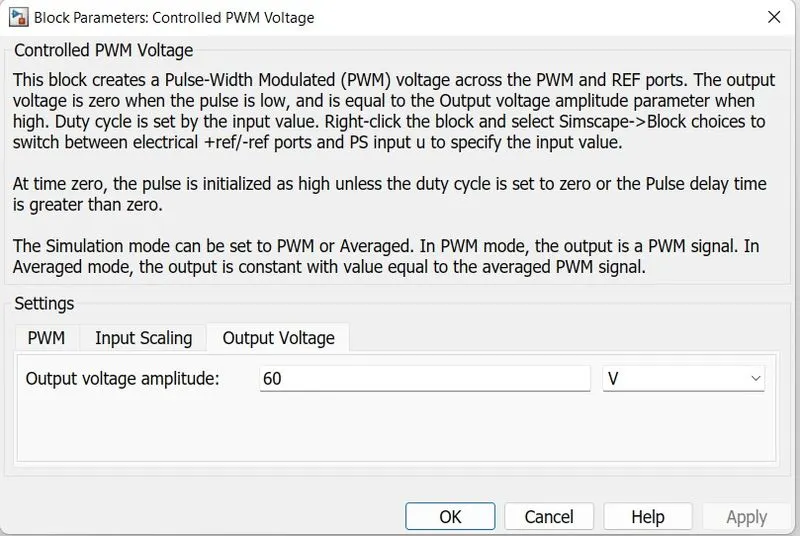
Controlled PWM Source
This block creates a Pulse-Width Modulated (PWM) voltage across the PWM and REF ports. The output voltage is zero when the pulse is low, and is equal to the Output voltage amplitude parameter when high. Duty cycle is set by the input value.
The Simulation mode can be set to PWM or Averaged. In PWM mode, the output is a PWM signal. In Averaged mode, the output is constant with value equal to the averaged PWM signal.
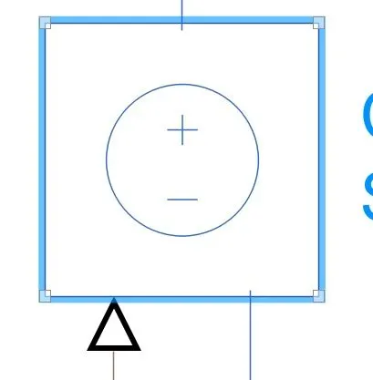
Controlled voltage source
The block represents an ideal voltage source that is powerful enough to maintain the specified voltage at its output regardless of the current passing through it. The output voltage is V = Vs, where Vs is the numerical value presented at the physical signal port.
Controlled current source
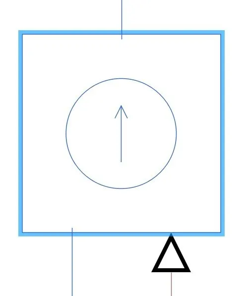
The block represents an ideal current source that is powerful enough to maintain the specified current through it regardless of the voltage across it. The output current is I = Is, where Is is the numerical value presented at the physical signal port
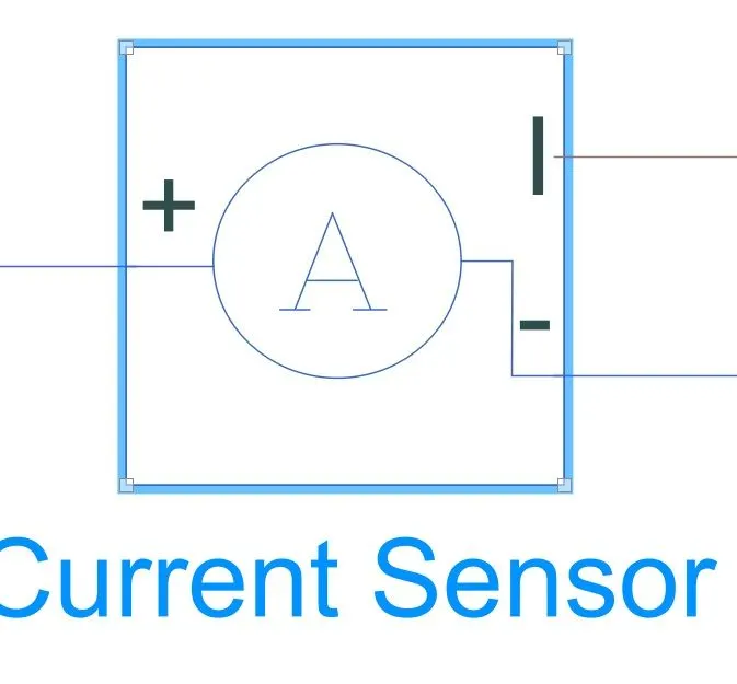
Current sensor
The block represents an ideal current sensor, that is, a device that converts current measured in any electrical branch into a physical signal proportional to the current.
BATTERY AND SOC SYSTEM
SOC System
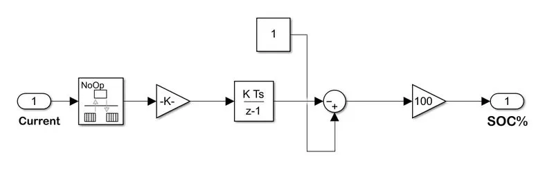
Battery
Implements a generic battery model for most popular battery types. Temperature and ageing (due to cycling) effects can be specified for Lithium-Ion battery type.
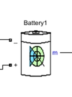
- The battery is required to power the controller and motor. The controller uses the battery power according to produce the input given by the motor to obtain maximum speed.
- The battery is also used to power every electrical component in the vehicle.
- The Battery block implements a generic dynamic model that represents the most popular types of rechargeable batteries.
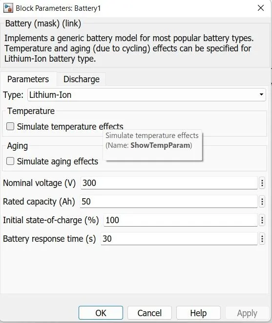
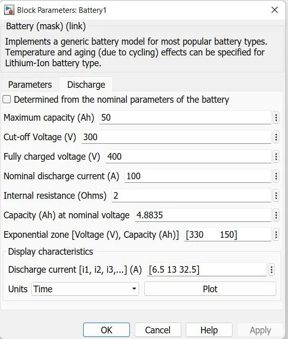
The battery has two-stage one is charging and another one is discharging state.
The battery is of 75Ah capacity.
The Nominal voltage of the battery is 330 V
Initial SoC is 100%
The battery as a series internal resistance plus a charge-dependent voltage source
defined by:
`V=(Vnom*SoC)/(1-beta*(1-soc)`
where SoC is the state of charge and Vnom is the nominal voltage.
Coefficient beta is calculated to satisfy a user-defined data point [AH1,VI].
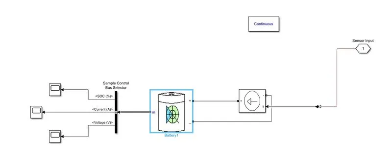
- The battery has a positive and negative terminal which is given the voltage-controlled source where the battery consumption is controlled by the motor controller and then it is given to the SOC block
Battery State of Charge:
- SoC is the percentage or level of battery presents after certain travel or consumption of battery charge by the vehicle.
- In the designed vehicle battery charge or SOC is calculated by giving it to the rate transition and then to gain where 1/inominal battery capacity) then to a discrete-time integrator and it will get minus from the 1 as it is considered a 100% of battery and it is multiplied with 100 to get a percentage of battery.
- The majority of blocks are simscape blocks were physical to Simulink converter is used to convert the physical signal from simscape block to Simulink signal
BUS Selector
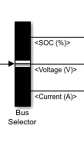
- The Bus Selector block outputs the signals you select from the input bus The block can output the selected elements separately or in a new virtual bus.
- Here just we have mange the output and connect it with different Scope Block.
PowerGUI
- The powerful block allows us to choose one of these methods to solve.
- Continuous, which uses a variable-step solver from Simulink your circuit
- Discretization of the electrical system for a solution at fixed time steps. Continuous or discrete phasor solution
- The powerful block also opens tools for steady-state and simulation results analysis and for advanced parameter design
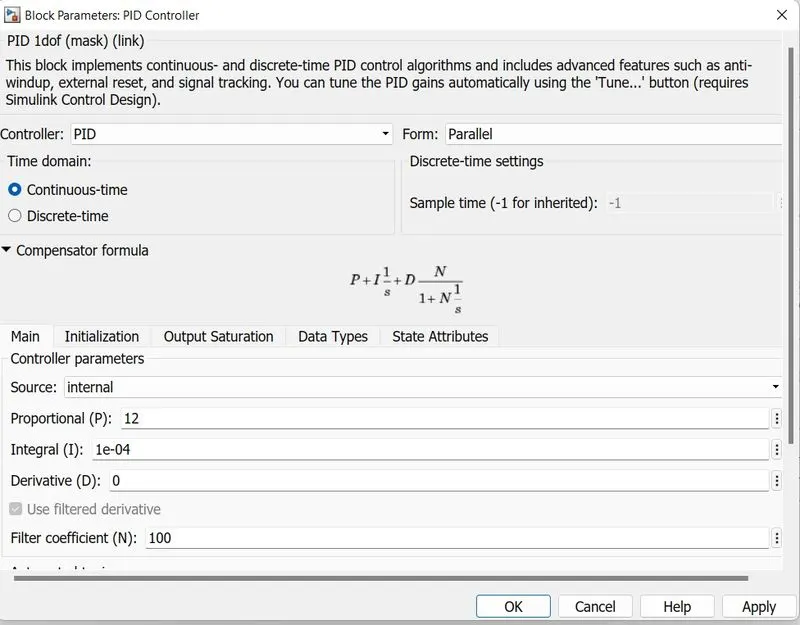
PID Controller
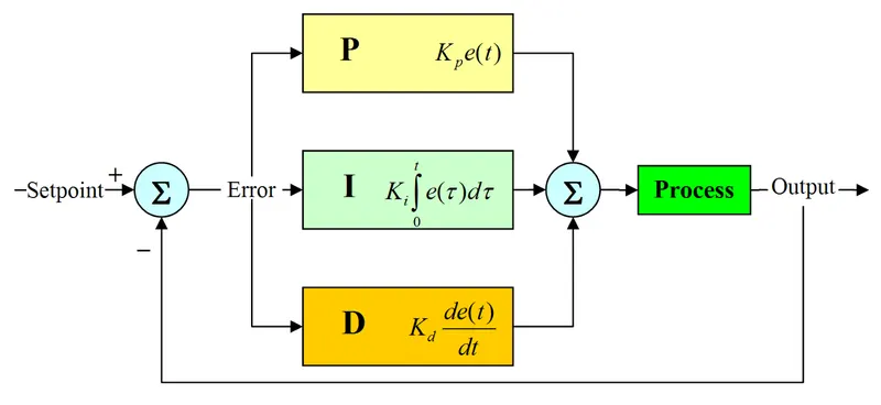
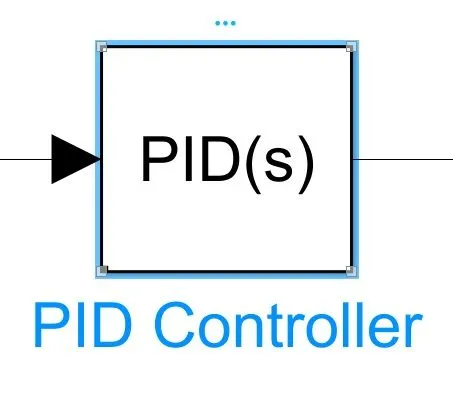
This block implements continuous- and discrete-time PID control algorithms and includes advanced features such as anti-windup, external reset, and signal tracking. You can tune the PID gains automatically using the 'Tune...' button (requires Simulink Control Design).
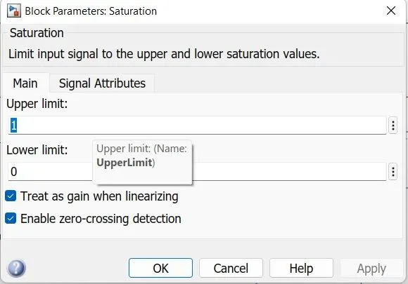
Acceleration saturation
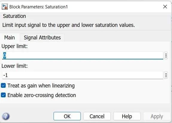
Deceleration saturation
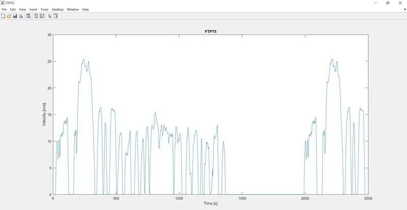
Reference Velocity (Drive Cycle):
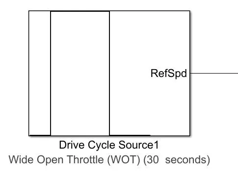
- The Drive Cycle Source block is used to provide the reference speed for the simulation.
- It generates a standard or user-specified longitudinal drive cycle.
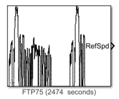
Generates a standard or user-specified longitudinal drive cycle.
The block output is the vehicle longitudinal speed.
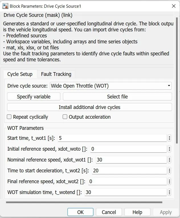
WIDE OPEN THROTTLE
Wide-open throttle or wide-open throttle (WOT), also called full throttle, is the fully opened state of throttle on an engine (internal combustion engine or steam engine)
SIMULATION RESULTS
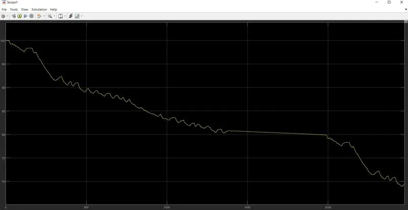
1) For FTP75 Drive Cycle:
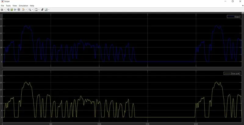
SOC Results
Controller and motor Temperature
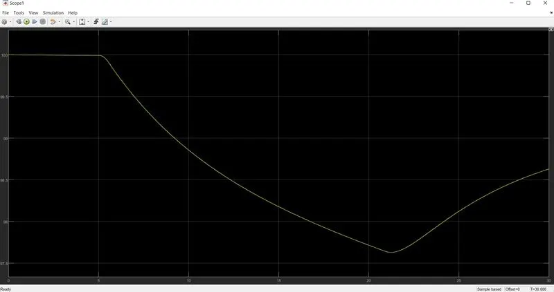
2) WOT Drive cycle
SOC Results
Controller and motor Temperature
CONCLUSION
Created a MATLAB model of an Electric car (four-wheel passenger vehicle) by using Li-ion battery, PM Brushed DC Motor. Determined the variations of Temperature of Motor and controller, SoC% and Energy consumed by the by vehicle for all the three Reference Drive cycles (.e: FTP75, WOT). This Battery powered car will be the most popular mode of transport in the future.