Week-7 Challenge: DC Motor Control
Explain a MATLAB demo model named ‘Speed control of a DC motor using BJT H-bridge’.
BJT or bipolar junction transistor ued for power switching applications.when it is conducting a forward voltage is developed between collector and emitter
H Bridge consist of four BJT or pairs of diode.two transistors are switched simultaneausly. Q1 and Q4 or Q2 and Q3.when Q1 and Q4 are conducting a positive voltage is applied to the motor and the diodes d2 and d3 operates as a freewheeling diode when Q1 and Q4 are switched off .after Q2 and Q3 are fired .negative voltage is applied to the motor and diodes D1 d4 act as a free wheeling diodes when Q2 and Q3 switched off
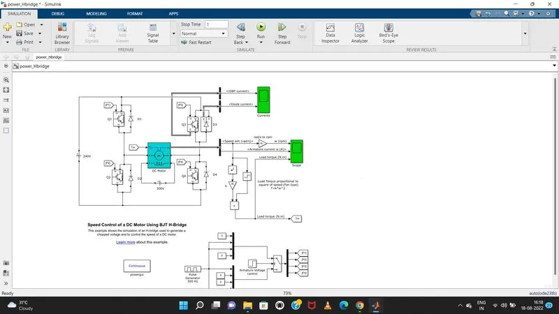
open matlab and run the demo of 'speed control of a dc motor using BJT H bridge ' keep the remaining variables same exmine the plot by using changing the pulse width in different percentages
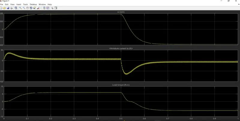
Comment on the armature current shoot-up from the scope results.
By changing the pulse width to 75%
By changing the pulse width to 55%
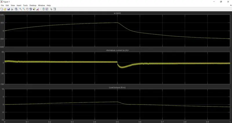
From the plot the 2nd plot got more steadier and smoother graph while compared to first. so by decreasing or controlling the duty cycle we can achieve this.
Comparison between Four-Quadrant Chopper DC Drive (DC7) block’and H-bridge model.
in four quadrant chopper dc drive the armature voltage is provided by an igbt converter controlled by 2 pi controllers.converter fed by 515v dc bus and rectification by 380 v 50 hz voltage source.to limit dc voltage during dynamic braking braking chopper must be added .
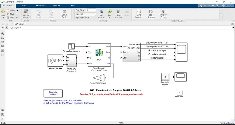
The first regulator is a speed regulator, followed by a current regulator. The speed regulator outputs the armature current reference (in p.u.) used by the current controller in order to obtain the electromagnetic torque needed to reach the desired speed.
The speed reference change rate follows acceleration and deceleration ramps in order to avoid sudden reference changes that could cause armature over-current and destabilize the system.
The current regulator controls the armature current by computing the appropriate duty ratios of the 5 kHz pulses of the four IGBT devices (Pulse Width Modulation). For proper system behavior, the instantaneous pulse values of IGBT devices 1 and 4 are opposite to those of IGBT devices 2 and 3. This generates the average armature voltage needed to obtain the desired armature current.
In order to limit the amplitude of the current oscillations, a smoothing inductance is placed in series with the armature circuit.
| FOUR QUADRANT DC CHOPPER DRIVE | H BRIDGE MODEL |
| To change the motor direction the polarity is changed | To change the motor direction the current signal has to be interrupted. |
| It has broader torque and power output ranges | It uses single pulse generator which gives narrow torque and power output range. |
| Up to 400v can be achieved. | upto 350v can be achieved |
| In this the current has chopped values. | in this the current has continuos values |
| Regenerative braking is possible | regenerative braking is not possible |
Develop a 2-quadrant chopper using simulink & explain the working of the same with the relevant results.
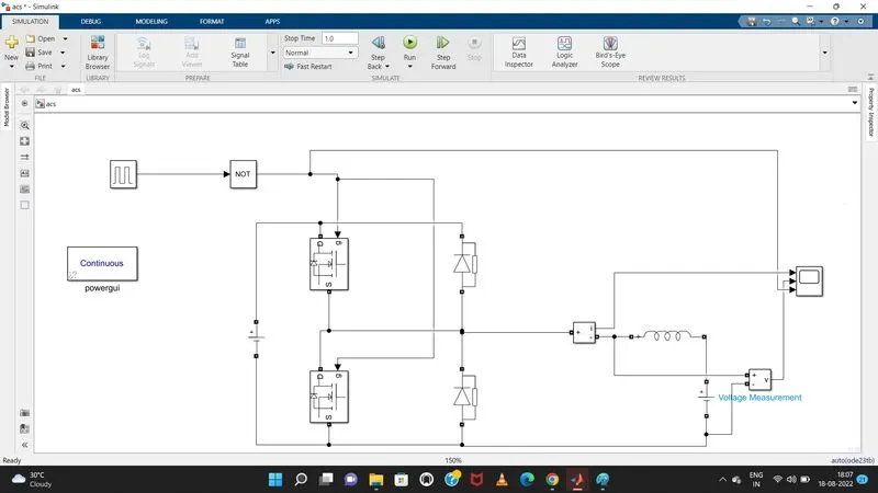
Hence, the simulink model corresponding to the circuit diagram is built using basic simulink blocks. The pulse generator is used with the NOT gate to prevent misfiring of the MOSFETs so that they do not conduct at the same time which results in the short circuit.
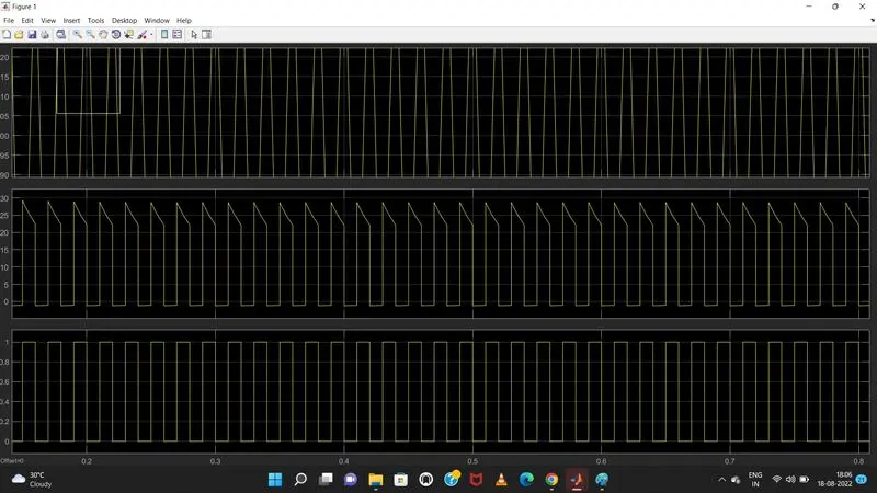
Amplitude taken as 20 with period of 0.02 sec
Hence, the simulink model corresponding to the circuit diagram is built using basic simulink blocks. The pulse generator is used with the NOT gate to prevent misfiring of the MOSFETs so that they do not conduct at the same time which results in the short circuit.
Explain in a brief about operation of BLDC motor.
As their name implies, brushless DC motors do not use brushes. With brushed motors, the brushes deliver current through the commutator into the coils on the rotor. So how does a brushless motor pass current to the rotor coils? It doesn’t—because the coils are not located on the rotor. Instead, the rotor is a permanent magnet; the coils do not rotate, but are instead fixed in place on the stator. Because the coils do not move, there is no need for brushes and a commutator.
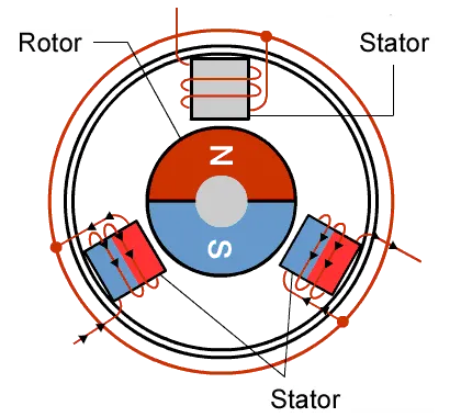
With the brushed motor, rotation is achieved by controlling the magnetic fields generated by the coils on the rotor, while the magnetic field generated by the stationary magnets remains fixed. To change the rotation speed, you change the voltage for the coils. With a BLDC motor, it is the permanent magnet that rotates; rotation is achieved by changing the direction of the magnetic fields generated by the surrounding stationary coils. To control the rotation, you adjust the magnitude and direction of the current into these coils.
Advantages
- efficiency because this can control continuosly at maximum torque
- BLDC motors can be controlled, using feedback mechanisms, to delivery precisely the desired torque and rotation speed.
- High durability
- low electric noise generation