Project 1 (Mini Project on Vehicle Direction Detection
AIM:
1. Development of MATLAB Simulink model as per requirement.
2. Tag the requirements to the Simulink model; tagging requirement 1 and requirement 2 to their corresponding subsystems is fine.
3. MBD-compliant changes, Data Dictionary creation & Code Generation is added advantage, and that is not the scope of this project.
4. If choosing code generation, the Storage class for input signals: ImportedExtern; the Storage class for Output signal: ExportToFile; Storage class for local signals: localizable; Storage class for calibration signals: Const.
5. Choose the sample time for all signals as 0.01s.
Requirement - 1:
- Steering wheel input as yaw rate (Signal name: SteeringWheel_YawDegreeInput) is the input for this system.
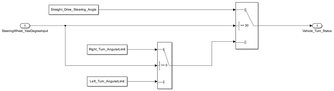
- This is compared against 3 angular values, one each for the left turn, right turn & straight drive (Calibration Values: Right_Turn_AngularLimit, Left_Turn_AngularLimit, Straight_Drive_Steering_Angle) to say which specific direction the steering wheel is turning towards.
- Use switch blocks to compare & develop this requirement. Keep this requirement in a subsystem & the output of this requirement is a local signal (Signal Name: Vehicle_Turn_Status).
Requirement - 2:
- Keep this requirement as a separate subsystem. Inputs to this requirement are local signals from requirement 1 (Signal Name: Vehicle_Turn_Status) & an input signal from the camera (Signal Name: CameraInput_RoadSign), which confirms the occurrence of a road sign.
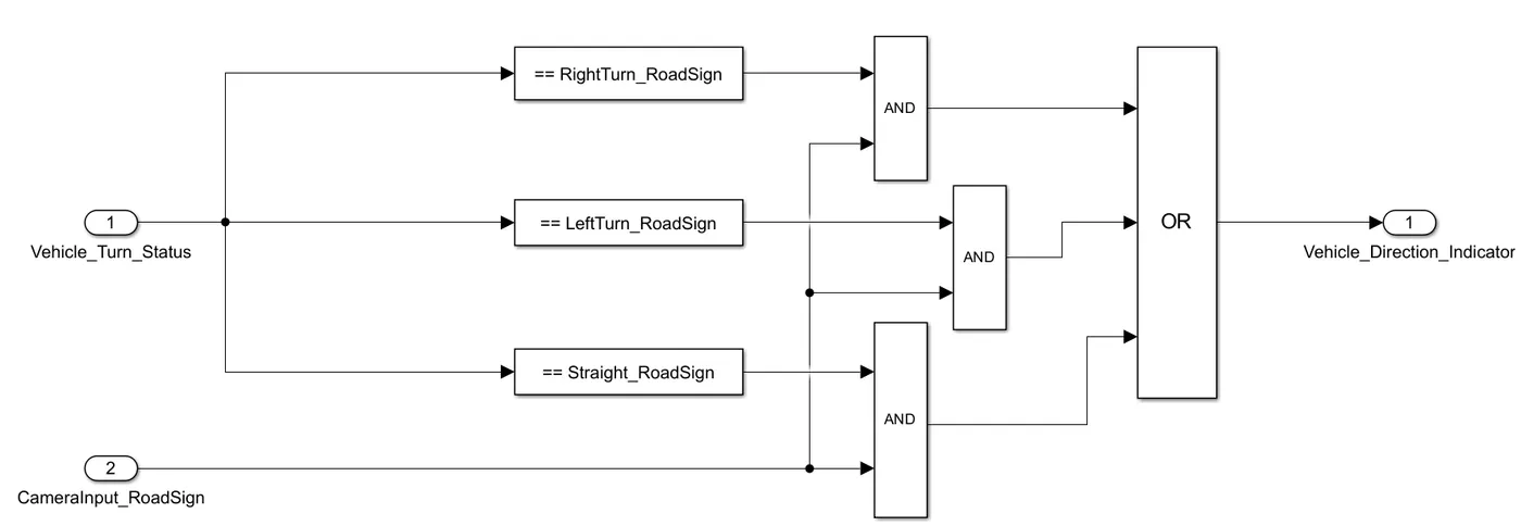
- Signal Vehicle_Turn_Status is compared against calibration values (Calibration Values: RightTurn_RoadSign, LeftTurn_RoadSign, Straight_RoadSign); if each of them is found equal, then each of the three corresponding outputs is compared against the camera input signal.
- Using a logical operator block, only one is finally given as the output signal (Signal Name: Vehicle_Direction_Indicator).
Signals & Calibration Data List:
| Signal/Calibration Name | Signal Type | Data Type | Dimension | Min | Max | Initial Value | Units |
| SteeringWheel_YawDegreeInput | Input | Int16 | 1 | -180 | 180 | - | Deg |
| CameraInput_RoadSign | Input | Boolean | 1 | 0 | 1 | - | - |
| Vehicle_Turn_Status | Local | Int16 | 1 | -180 | 180 | - | Deg |
| Right_Turn_AngularLimit | Calibration | Int16 | [1 1] | -180 | 180 | 30 | Deg |
| Left_Turn_AngularLimit | Calibration | Int16 | [1 1] | -180 | 180 | -120 | Deg |
| Straight_Drive_Steering_Angle | Calibration | Int16 | [1 1] | -180 | 180 | 0 | Deg |
| RightTurn_RoadSign | Calibration | Int16 | [1 1] | -180 | 180 | 30 | - |
| LeftTurn_RoadSign | Calibration | Int16 | [1 1] | -180 | 180 | -120 | - |
| Straight_RoadSign | Calibration | Int16 | [1 1] | -180 | 180 | 0 | - |
| Vehicle_Direction_Indicator | Output | Boolean | 1 | 0 | 1 | - | - |
Description:
Identifying the vehicle's direction is one of the important & diverse features of Autonomous Driving & Advanced Driver Assistance Features. This particular sub-feature of identifying the direction of a vehicle is identifying the direction the vehicle is taking based on the camera input.
The camera reads the road signs & stores them in its memory with unique values for left turn, right turn & straight drive. Depending on the direction it is taking, the final indication is given to the driver - as an indication if he is driving in the recommended direction.
Vehicle Direction Determination can also be coupled with features like GPS systems to identify whether the vehicle is reaching its destination optimally. This sub-feature can be used along with Lane Detection, Highway Warning, and Ramp Entry / Exit in Wrong Way Detection.
Simulink Model
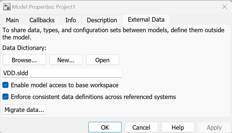
- Open the Model Properties and select the Link to Data Dictionary. Go to External Data and click on New. Create your sldd file and click on OK.
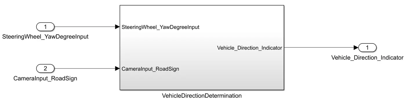
- Now, create a subsystem Vehicle_Direction_Determination with the input as SteeringWheel_YawDegree & CameraInput_RoadSign and output as Vehicle_Direction_Indicator.
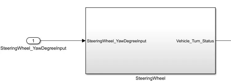
- Under the subsystem, create two subsystems. From the first subsystem, SteeringWheel, implement the given requirement. Take the SteeringWheel_YawDegree as input and, accordingly, give the output as Vehicle_Turn_Status. Use the switch block to fulfil the given requirement.
- The following is the representation of the first subsystem:
- Now, create the second subsystem, VehicleDirection, which will take the output of the first subsystem, Vehicle_Turn_Status, and CameraInput_RoadSign as input.
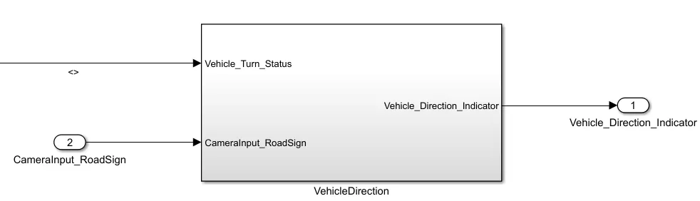
- Then, we use a conditional block under the second system to get the result. Comparing every road sign, we will get which turn the vehicle takes (left, right or straight).
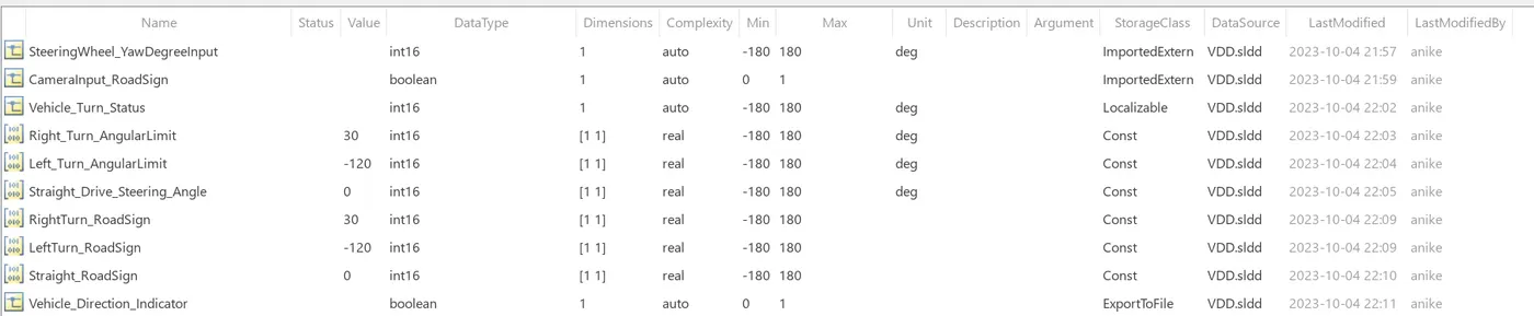
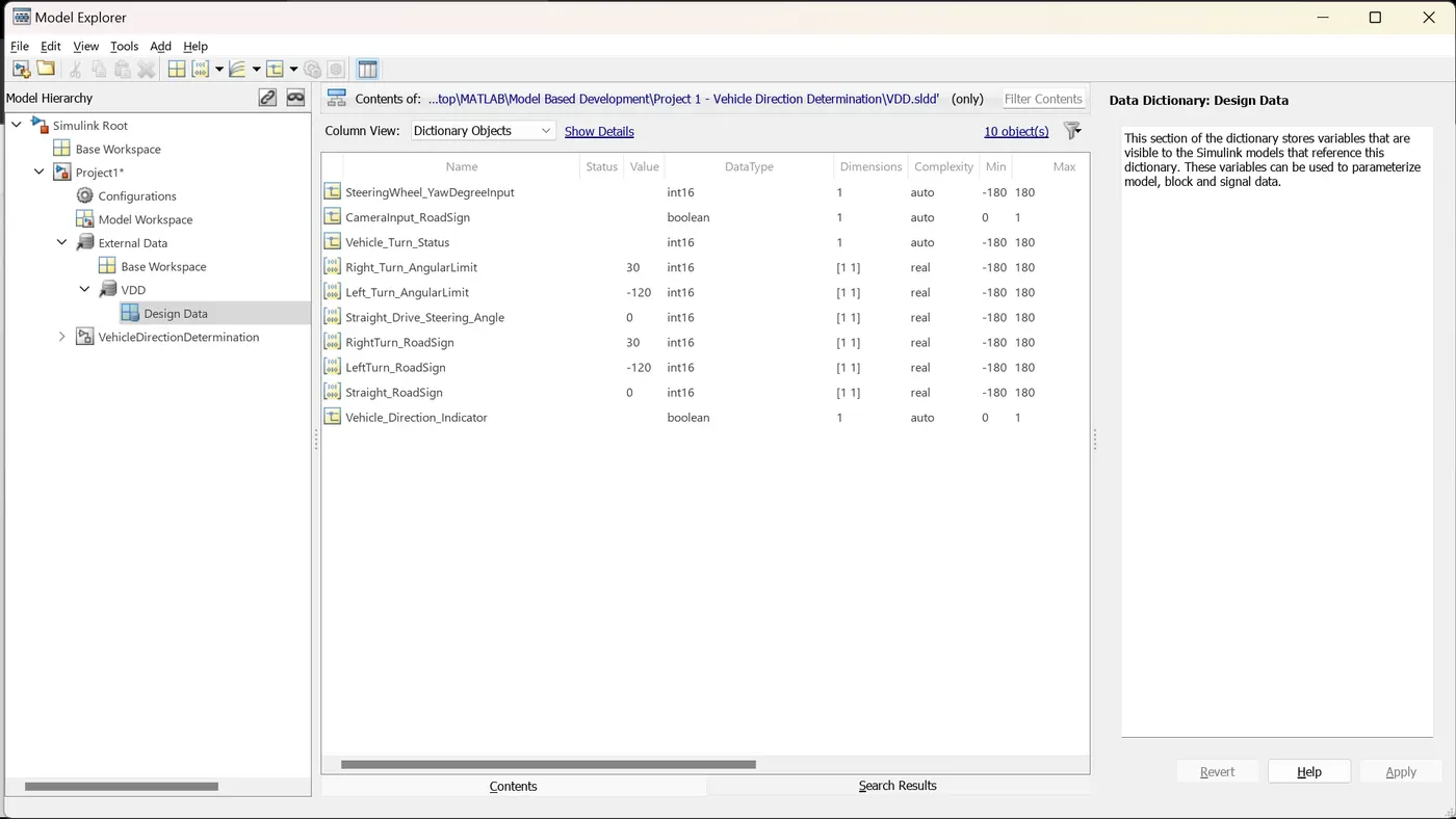
- Now go to Model Data, which is left below the Simulink Model. Select External Data. Go to the sldd file name and select Design Data. Add all the variables provided in the question. Right-click on the sldd filename and select Save Changes to save the Data Dictionary.
- To get the code generated, do the following steps:
Right-click on the main subsystem → Block Parameters (Subsystem) → Tick on Treat as atomic size → Model Configuration → Solver (Fixed Step) → Sample Time (0.01s) → Code Generation → ert.tlc → App (Embedded Code) → Build (Generate Code).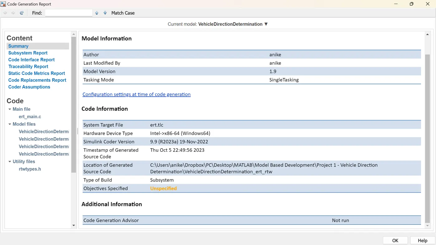
/* * Academic License - for use in teaching, academic research, and meeting * course requirements at degree granting institutions only. Not for * government, commercial, or other organizational use. * * File: ert_main.c * * Code generated for Simulink model 'VehicleDirectionDetermination'. * * Model version : 1.19 * Simulink Coder version : 9.9 (R2023a) 19-Nov-2022 * C/C++ source code generated on : Fri Oct 6 20:47:27 2023 * * Target selection: ert.tlc * Embedded hardware selection: Intel->x86-64 (Windows64) * Code generation objectives: Unspecified * Validation result: Not run */ #include #include /* This example main program uses printf/fflush */ #include "VehicleDirectionDetermination.h" /* Model header file */ /* * Associating rt_OneStep with a real-time clock or interrupt service routine * is what makes the generated code "real-time". The function rt_OneStep is * always associated with the base rate of the model. Subrates are managed * by the base rate from inside the generated code. Enabling/disabling * interrupts and floating point context switches are target specific. This * example code indicates where these should take place relative to executing * the generated code step function. Overrun behavior should be tailored to * your application needs. This example simply sets an error status in the * real-time model and returns from rt_OneStep. */ void rt_OneStep(void); void rt_OneStep(void) { static boolean_T OverrunFlag = false; /* Disable interrupts here */ /* Check for overrun */ if (OverrunFlag) { rtmSetErrorStatus(VehicleDirectionDeterminatio_M, "Overrun"); return; } OverrunFlag = true; /* Save FPU context here (if necessary) */ /* Re-enable timer or interrupt here */ /* Set model inputs here */ /* Step the model */ VehicleDirectionDetermination_step(); /* Get model outputs here */ /* Indicate task complete */ OverrunFlag = false; /* Disable interrupts here */ /* Restore FPU context here (if necessary) */ /* Enable interrupts here */ } /* * The example main function illustrates what is required by your * application code to initialize, execute, and terminate the generated code. * Attaching rt_OneStep to a real-time clock is target specific. This example * illustrates how you do this relative to initializing the model. */ int_T main(int_T argc, const char *argv[]) { /* Unused arguments */ (void)(argc); (void)(argv); /* Initialize model */ VehicleDirectionDetermination_initialize(); /* Attach rt_OneStep to a timer or interrupt service routine with * period 0.01 seconds (base rate of the model) here. * The call syntax for rt_OneStep is * * rt_OneStep(); */ printf("Warning: The simulation will run forever. " "Generated ERT main won't simulate model step behavior. " "To change this behavior select the 'MAT-file logging' option.\n"); fflush((NULL)); while (rtmGetErrorStatus(VehicleDirectionDeterminatio_M) == (NULL)) { /* Perform application tasks here */ } /* Terminate model */ VehicleDirectionDetermination_terminate(); return 0; } /* * File trailer for generated code. * * [EOF] */ -
Requirements Tagging
a. Create a Word file for each requirement.
b. Copy-paste the statements to the respective requirement Word file.
c. Now scan the entire paragraph.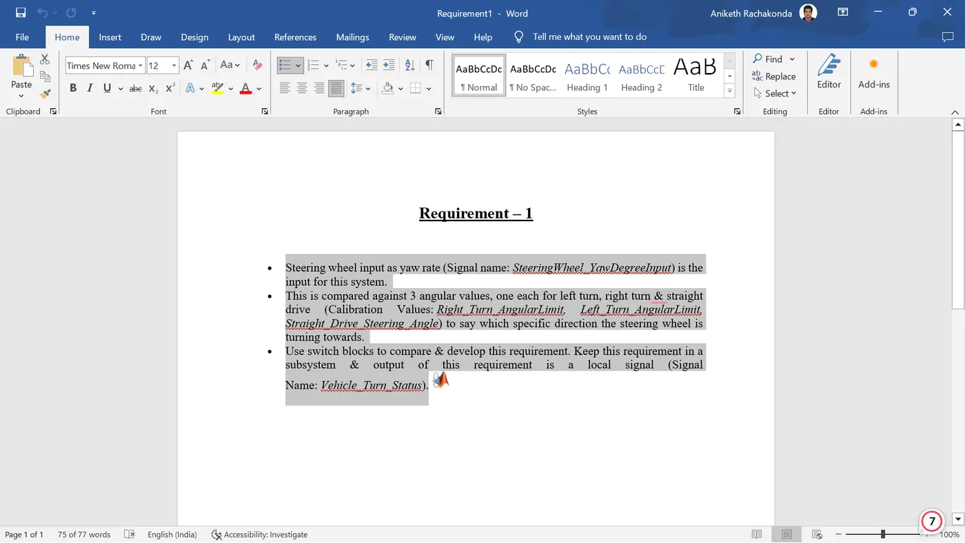
d. Go to the subsystem in the MATLAB Simulink and right-click the first subsystem → Requirements → Link to Selection in Word.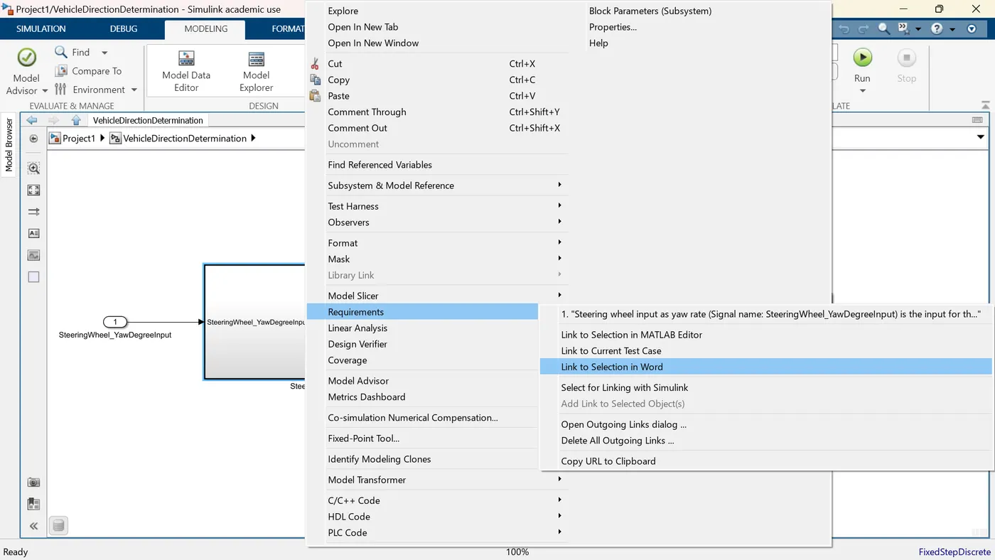
e. You will observe the MATLAB symbol occurring at the end-point. This indicates that the Requirement1.docx has been tagged to the MATLAB Simulink.The same procedure is followed for the Requirement - 2.
Conclusion:
- I have developed a MATLAB Simulink model of Vehicle Direction Determination as per requirement.
- I have tagged the requirements to the Simulink model.
- I have done MBD-compliant changes, created a Data Dictionary, and generated code.