Project 1 (Mini Project on Vehicle Direction Detection
Aim:
To create a Simulink model of Vehicle Direction Detection as per the Requirement data.
Requirement - 1:
- Steering wheel input as yaw rate (Signal name: SteeringWheel_YawDegreeInput) is the input for this system.
- This is compared against 3 angular values, one each for left turn, right turn & straight drive (Calibration Values: Right_Turn_AngularLimit, Left_Turn_AngularLimit, Straight_Drive_Steering_Angle) to say which specific direction the steering wheel is turning towards.
- Use switch blocks to compare & develop this requirement. Keep this requirement in a subsystem & output of this requirement is a local signal (Signal Name: Vehicle_Turn_Status).
Requirement – 2:
- Keep this requirement as a separate subsystem. Inputs to this requirement are local signal from requirement 1 (Signal Name: Vehicle_Turn_Status) & an input signal from camera (Signal Name: CameraInput_RoadSign), which confirms the occurrence of a road sign.
- Signal Vehicle_Turn_Signal is compared against calibration values (Calibration Values: RightTurn_RoadSign, LeftTurn_RoadSign, Straight_RoadSign), if each of them is found equal, then each of the three corresponding output is compared against the camera input signal,
- Using a logical operator block, only one among them is finally given as output signal (Signal Name: Vehicle_Direction_Indicator).
Objectives of the project:
- Development of MATLAB Simulink model as per requirement.
- Tag the requirements to the simulink model; tagging requirement 1 & requirement 2 to their corresponding subsystems is fine.
- MBD compliant changes, Data Dictionary creation & code generation is added advantage, and that is not scope of this project.
- If choosing code generation, Storage class for Input signals: ImportedExtern; Storage class for Output signal: Export to File; Storage class for local signals: localizable; Storage class for calibration signals: Const.
- Choose sample time for all signals as 0.01s
- Choose sample time for all signals as 0.01s
Signals & Calibration Data List:
|
Signal / Calibration Name |
Signal Type |
Data Type |
Dimension |
Min |
Max |
Initial Value |
Units |
|
SteeringWheel_YawDegreeInput |
Input |
Int16 |
1 |
-180 |
180 |
- |
Deg |
|
CameraInput_RoadSign |
Input |
Boolean |
1 |
0 |
1 |
- |
- |
|
Vehicle_Turn_Status |
Local |
Int16 |
1 |
-180 |
180 |
- |
Deg |
|
Right_Turn_AngularLimit |
Calibration |
Int16 |
[1 1] |
-180 |
180 |
30 |
Deg |
|
Left_Turn_AngularLimit |
Calibration |
Int16 |
[1 1] |
-180 |
180 |
-120 |
Deg |
|
Straight_Drive_Steering_Angle |
Calibration |
Int16 |
[1 1] |
-180 |
180 |
0 |
Deg |
|
RightTurn_RoadSign |
Calibration |
Int16 |
[1 1] |
-180 |
180 |
30 |
|
|
LeftTurn_RoadSign |
Calibration |
Int16 |
[1 1] |
-180 |
180 |
-120 |
|
|
Straight_RoadSign |
Calibration |
Int16 |
[1 1] |
-180 |
180 |
0 |
|
|
Vehicle_Direction_Indicator |
Output |
Boolean |
1 |
0 |
1 |
- |
Blocks used:
Blocks used to create a model are
Input Blocks: To provide the input signals
Output Blocks: To send the output signals
Constant Blocks: To define the calibration values
Logical operator Blocks: OR blocks are used to compare and the road signs with camera input and to get the boolean output.
Switch Blocks: To compare the input with the calibration values.
Mux Block: To combile the signals
Display Block: To display the results
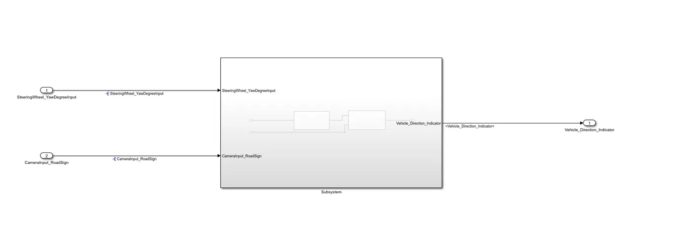
Simulink Model:
Requirement_1:
Requirement_2:
Simulink Data Dictonary:
Model Advisor Report:
Method:
The logic of Requirement_1 is that if the input is >=30 (because the initial value is 30), the car will turn right. If the input is not equal to zero (~=0), the car will turn left. Otherwise, the car will turn left. straight_drive (if input is zero).
The input deviation rate is given to the central port of the switch and the threshold is 30. The switch takes a True condition (Right_Turn_AngularLimit) if the input is greater than the threshold, and a False condition otherwise. In the second switch, the threshold is 0. If the threshold is not equal to 0, the switch takes a true condition (Left_Turn_AngularLimit), otherwise it takes a false condition (Sitight_Drive Steering_Angle). This output from the second switch is given to the first switch as a false state. The output of Requirement_1 is "Vehicle_Turn_Status".
The logic of Requirement_2 is to compare "Vehicle_Turn_Status" (output of Requirement_1) with the input signal from "RoadSign" and the camera to get the vehicle direction indicator.
After comparing with "Vehicle_Turn_Status", if they are equal, each of the three outputs corresponding to the camera's input signal is compared using "logical OR" and obtains the true case block, which is only one of them. Get as below. : The output uses the "Mux" block.
And the final output from the Vehicle_Detection Model shows the direction of the vehicle_direction.
It is then defined by adding the SLDD_file to the model and loading the calibration and input/output values.
When you run the simulation, the direction of the vehicle is obtained.
TAGGING:
To perform Tagging first we have to create a word file with all details reagarding about the model we are creating. Tagging enables us to view the procedure which is used to build the model or to know more details about the designed model. To tag the given requirement blocks the followinng procedure has been followed.
- First we need select the respective heading in the word file. Like in the followinng figure we can see that Requirement1 is a heading in which the procedure to build the model has been given.
- The word file which is created must be saved in the same folder of our simulink model.
In the above figure it show the selection of word, now to tag this to the subsystem:
- Right click on the respective subsystem, as we have selected a word regarding about requirement1 we are right clicking on 1 subsyetm.
- Go to Requirements option from the context. In requirements select Link to selection in word.
- If we click on that it is automatically tagged to the word in word file.
Now will be able to see the tagging. Repeat same procedure like right click on subsystem go to requirements and from the options, the top 1. represents the word which is tagged to the subsystem.
- To know about the subsytemm building or any other details which are written in the word file, click on that 1st option it will take you to the word file requirement1 section.
Repeat the same procedure for Requirement2 subsystem also. Select the relatable heading in the word file and do the same procedure.
- After the proccedure will be able to the Requiremet2 word which is tagged at the top of requirements section.
- Which is shown in the following figure.
SOLVER SETTINGS:
Solver settings are important to simulate the model. To open the solver setings, go to the Modeling section which is at the top of simulink window. And select the Model settings under the modeling section. Which is shown in the following figure.
After clicking on model settings the following window will appears. The window presents the configuration of the parameters in our simulink mode.
- In the configuration window, click on solver to model the solver parameters.
- Now change the type to Fixed-step, Solver to discrete(no continuous states) and take sample time as 0.01sec. Then click Ok.
- This settings are shown in the following figure.
In the same configuration window there another settings to model, which is Code generation. Click on code generation,
- Choose the system targer file as ert.tlc (Embedded coder) by clicking on the browse option.
- Then click on Ok and close the window.
MAB GUIDEINES:
The MAB (MathWorks Advisory Board) Guidelines are a set of modeling guidelines developed by an independent industry working group for the usage of MATLAB, Simulink, Stateflow and Embedded Coder. The guidelines are the culmination of years of engineering expertise and best practices for developing, maintaining and documenting control algorithm models used in the development of production software.
- To perform the MAB guidelines test on our simulink model, go to modeling section and select Model Advisor which is at the top left corner of the window.
- You can use the Model Advisor to verify compliance of your model with the MathWorks Advisory Board (MAB) guidelines.
By clicking on the Model Advisor, a window will ask us to confirmation if we click on Ok then it will opens a window which is shown in the following figure.
- In the Model advisor there are number of guidelines, among them will select only Modeling Standards fro MAB.
- If we expand the section will be able to see which are tested under the MAB guidelins. If we again expand there will be many sub sections in each section.
- After selecting MAB guidelines, click on Run Selected checks.
- Then it asks again for confirmation, click on continue. Then the testing will begins. It takes time to perform the guidelines test.
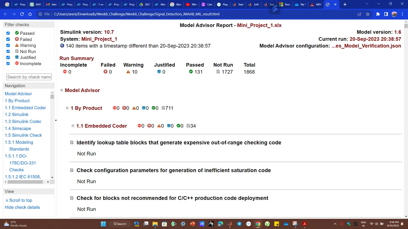
After the MAB guidelined test completion, it should be mandatory that 0 fail conditions. If any fail conditions are there rectify them and again make them to 0. The warnings are permittable to some limit.
- After getting 0 fails click on Generate report. This report will gives all data about the smulink model we have created.
After clicking Generate report in the above window, a popup window will appears as shown in the followinng figure.
- It shows the directory, at where the report is going to save. It will save in the same folder of our simulink model.
- Give a name to the report. Then click on OK.
JmAAB Result:
Conclusion:
Autonomous vehicles consists of various Advance Driver-Assistance System (ADAS) features. Vehicle Driection Detection is one the features of the vehicles.
Hence, created an Simulink model of Vehicle Direction Detection as per the Requirement data.