Project 1 (Mini Project on Vehicle Direction Detection
Aim:
To design a model which assist the driver to turn the vehicel according to the signs in the road taken through a camera .
The driver can adjust the direction as compared to the present location of the vehicle.
Model:
The model fof controlling the direction takes two input namely the current direction of the steering and the camera input for the sign detected in the road.
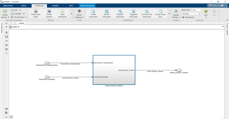
The two inputs are given to the entire vehicel direction detection subsystem.The output of the system is the vehicle direction indicator.Now we can look into the subsystem,
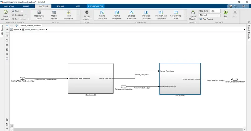
The subsystem consists of other two subsystem.The two inputs taken are split into the two systems.The model requires two requirements to perform the operation .So two subsystems are created.Now we can look into the requirement 1.
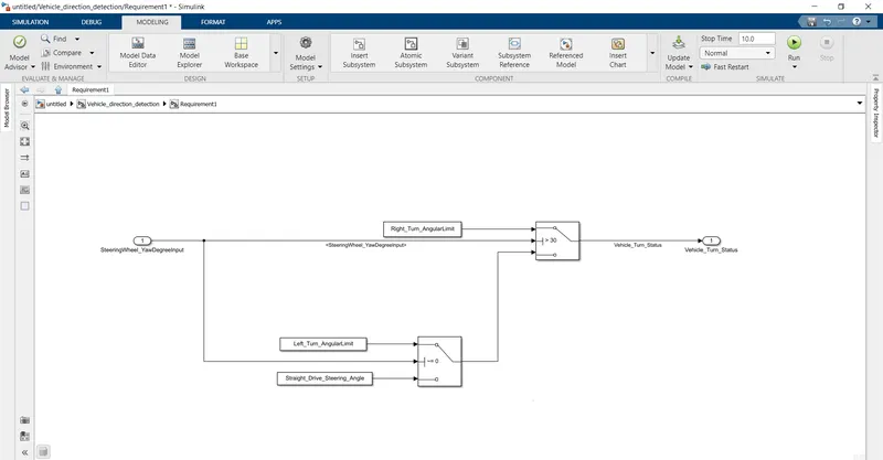
The requirement 1 subsystem will look like the one above.The input steerwheel input is compared with the calibrated values like rightturn angle,left turn angle and straight drive angle to detect the current direction of the vehicle.
The switch block is used to compare the signals.If the input value is zero then the straight drive value will be selected or else the left turn angle will be selected as the predefined value of straight angle is given as zero.The compared value is then compared with the right angle as the input is greater than 30 then the right angle will get as output or else the compared value will get as the output since the right turn value is given as 30.The output from the subsystem is vehicle turn status.
Now we can look into the requirement 2 subsystem.
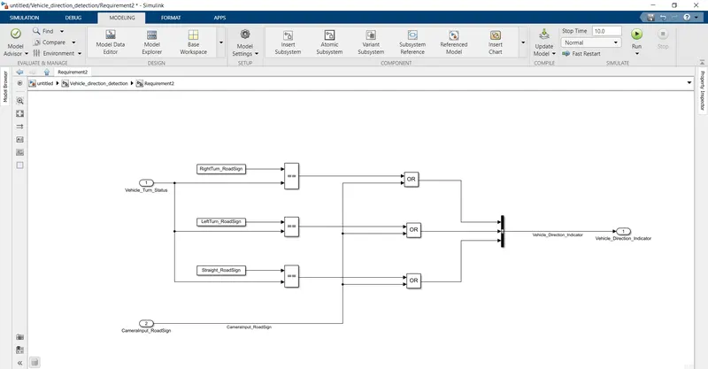
The output from the requirement 1 is taken as the input to the system along with the camera input signal.The vehicle turn status is compared with the default sign values as right left and straight signs.If the both are equal then the output is generated which is added with the camera signal and then the output is produced.The output produced is the vehicle direction indicator based on which the driver can adjust the vehicle.
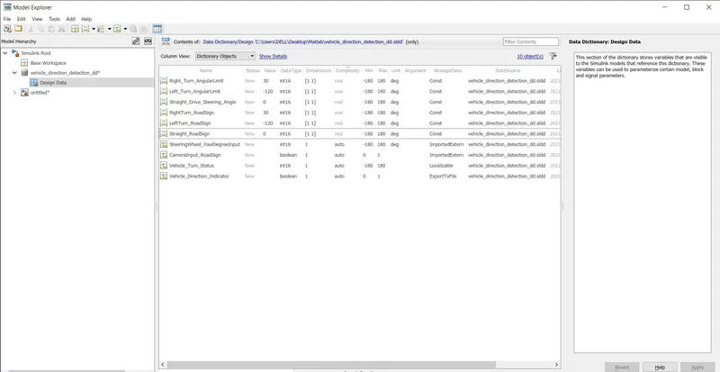
The above is the sldd file for the above created model.All the signals are declared in the library file.The input signals being of imported extern,output is of export to file and the calibration values are of caonst storage type.The values of the calibration blocks are also given here.
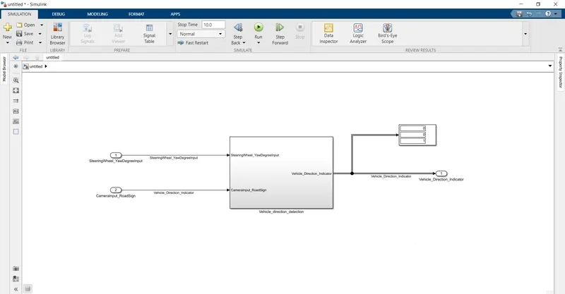
The simulation is run with the display block for displaying the output.The output from the display block will guide the driver to take correct measure for the direction of the vehicle .He can adjust the vehicle according to the output displayed.