Project 1 (Mini Project on Vehicle Direction Detection
Aim:
To built the Vehicle direction determination using the camara and the SteeringWheel_YawDegree angle as inputs and indicating the vehicle direction.
Camera reads the road signs & stores into its memory with unique values for left turn, right turn & straight drive. Depending on the direction it is taking, final indication is given to the driver – as an indication if he is driving in the recommended direction or not.
Objective of Mini Project:
- Development of MATLAB Simulink model as per requirement.
- Tag the requirements to the simulink model; tagging requirement 1 & requirement 2 to their corresponding subsystems is fine.
- MBD compliant changes, Data Dictionary creation & code generation is added advantage, and that is not scope of this project.
- If choosing code generation, Storage class for Input signals: ImportedExtern; Storage class for Output signal: Export to File; Storage class for local signals: localizable; Storage class for calibration signals: Const.
- Choose sample time for all signals as 0.01s
Steps for building the model:
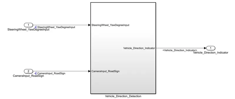
Step-1 : Find the inputs and outputs from the given data.
Inputs:
1) SteeringWheel_YawDegree
2) CameraInput_RoadSign
Output:
1) Vehicle_Direction_Indicator
Design the base sub system "Vehicle_Direction_Detection" with the input and output ports as shown below
Step-2:
Design the Requirmnet-1 as given
Requirement - 1:
- Steering wheel input as yaw rate (Signal name: SteeringWheel_YawDegreeInput) is the input for this system.
- This is compared against 3 angular values, one each for left turn, right turn & straight drive (Calibration Values: Right_Turn_AngularLimit, Left_Turn_AngularLimit, Straight_Drive_Steering_Angle) to say which specific direction the steering wheel is turning towards.
- Use switch blocks to compare & develop this requirement. Keep this requirement in a subsystem & output of this requirement is a local signal (Signal Name: Vehicle_Turn_Status).
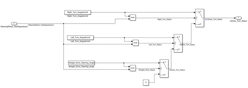
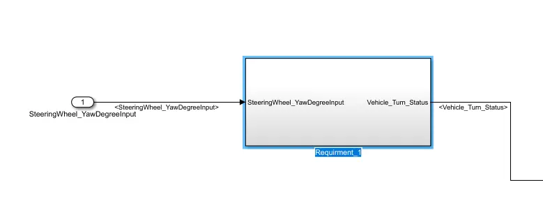
This is designed in a saparate subsystem in the main sub subsytem " Requirment_1 "
Step-3:
Design the Requirmnet- 2 as given
Requirement – 2:
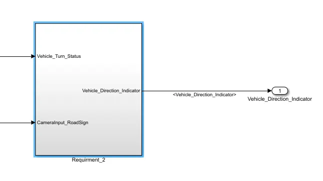
- Keep this requirement as a separate subsystem. Inputs to this requirement are local signal from requirement 1 (Signal Name: Vehicle_Turn_Status) & an input signal from camera (Signal Name: CameraInput_RoadSign), which confirms the occurrence of a road sign.
- Signal Vehicle_Turn_Status is compared against calibration values (Calibration Values: RightTurn_RoadSign, LeftTurn_RoadSign, Straight_RoadSign), if each of them is found equal, then each of the three corresponding output is compared against the camera input signal,
- Using a logical operator block, only one among them is finally given as output signal (Signal Name: Vehicle_Direction_Indicator).
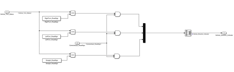
This is designed in a saparate subsystem in the main sub subsytem " Requirment_2 "
Step-4:
- As given in the Requirment-1 the inputs is the SteeringWheel_YawDegree and output is Vehicle_Turn_Status.
- As given in the Requirment-2 the inputs are Vehicle_Turn_Status from Requirment-1 and Camara input and the output is Vehicle_Direction_Indicator
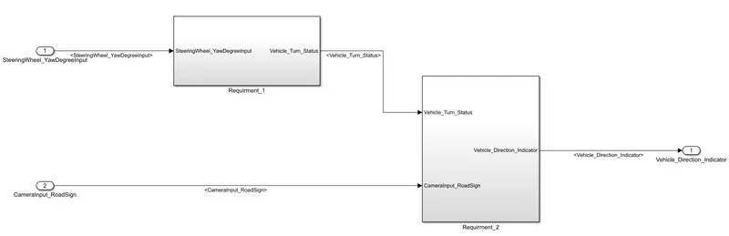
Up till now the Objective 1 is completed.
Step- 5:
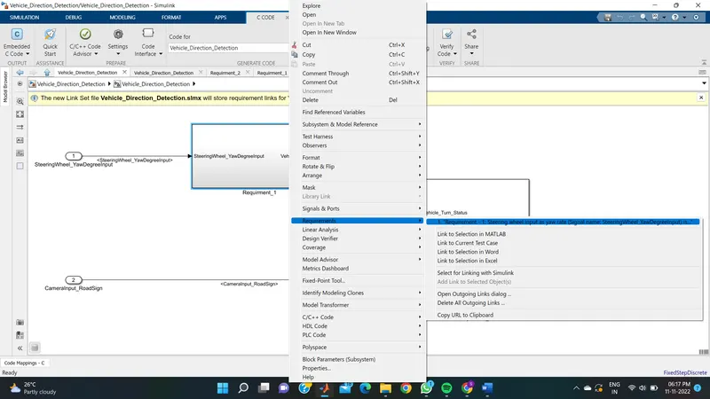
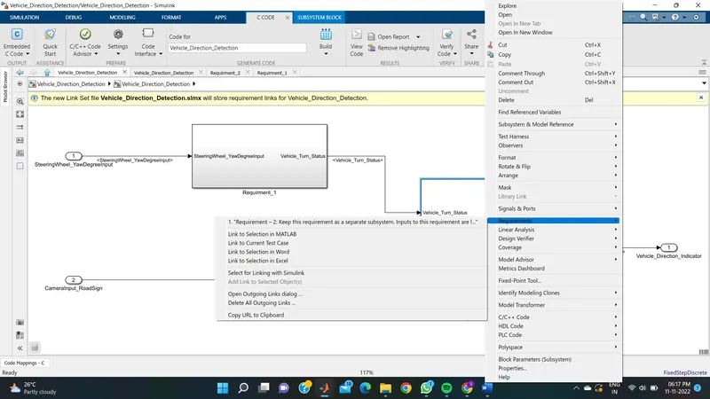
Objective 2 - Tag the requirements to the simulink model; tagging requirement 1 & requirement 2 to their corresponding subsystems is fine.
The word is uploaded in the files with a name of "tagr_eq1 nd 2" and tagged with the Requirment-1 and 2
Step-6:
Objective 3
Data Dictionary creation
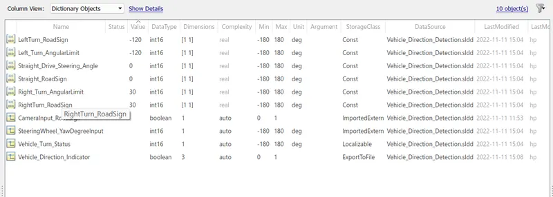
Creat the SLDD file as given data for the model as shown in figure below
Given data :
Signals & Calibration Data List:
|
Signal / Calibration Name |
Signal Type |
Data Type |
Dimension |
Min |
Max |
Initial Value |
Units |
|
SteeringWheel_YawDegreeInput |
Input |
Int16 |
1 |
-180 |
180 |
- |
Deg |
|
CameraInput_RoadSign |
Input |
Boolean |
1 |
0 |
1 |
- |
- |
|
Vehicle_Turn_Status |
Local |
Int16 |
1 |
-180 |
180 |
- |
Deg |
|
Right_Turn_AngularLimit |
Calibration |
Int16 |
[1 1] |
-180 |
180 |
30 |
Deg |
|
Left_Turn_AngularLimit |
Calibration |
Int16 |
[1 1] |
-180 |
180 |
-120 |
Deg |
|
Straight_Drive_Steering_Angle |
Calibration |
Int16 |
[1 1] |
-180 |
180 |
0 |
Deg |
|
RightTurn_RoadSign |
Calibration |
Int16 |
[1 1] |
-180 |
180 |
30 |
|
|
LeftTurn_RoadSign |
Calibration |
Int16 |
[1 1] |
-180 |
180 |
-120 |
|
|
Straight_RoadSign |
Calibration |
Int16 |
[1 1] |
-180 |
180 |
0 |
|
|
Vehicle_Direction_Indicator |
Output |
Boolean |
1 |
0 |
1 |
- |
- |
SLDD file:
Step-7:
Objective 3,4 and 5
Code generation
- Initially make the system as Atomic system
- Open the model setting
- Make the Solver as Fixed step with Discrete as shon below
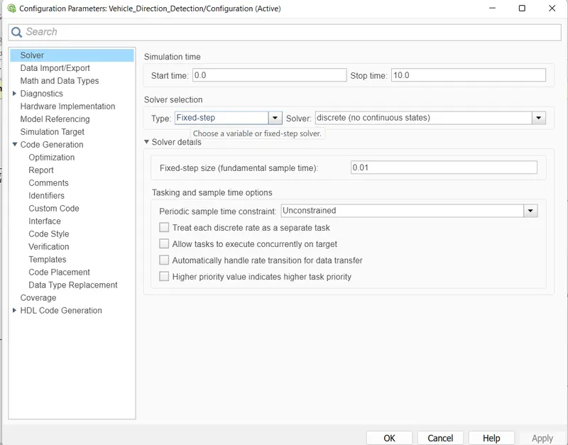
4. Sleclect the Code generation and change System target file to ert.tle Embedded and apply

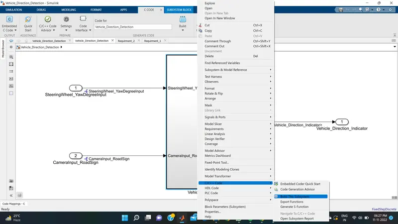
5. Generate the Code and make the S-function block using the buld option as shown below, A code file is generated in the Woring directory.
For code building
For S-function block
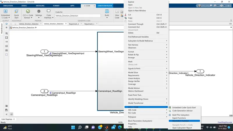
The code file is saved in working directory wit the name of "Vehicle_Direction_Detection_ert_rtw" it is upladed in the file.
Result :
The model is created according to requirments and acchived the objectives as mentioned in the project. The code and S-function block is also created for the SIL test. For the testing we need to creat the test cases and test the model for SIL and MIL test to observe the output.