Project 1 (Mini Project on Vehicle Direction Detection
Aim: To identify the direction of vehicle which is a feature in Autonomous Driving by taking the "Camera Input & YawDegree Input".
Blocks Used:
- Input/Output Ports
- Constant
- Compare to Constant
- Switch
- Relational Operator
- And logic
- Signal Converter
- Mux
Now we will go into the subsystems.
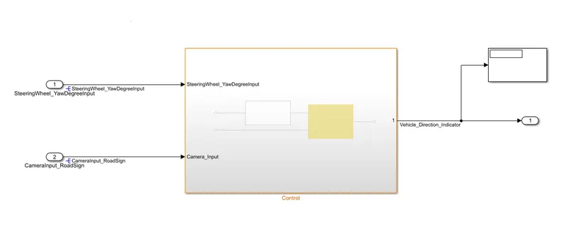
- The entire unit is fed with two signals i.e., SteeringWheel_YawDegree input to turn the vehcile wheels and CameraInput_Roadsign will control the speed and brake operation while taking a turn.
- We are taking the Direction indicator as the output i.e., right turn or the left turn.
Inside Control:
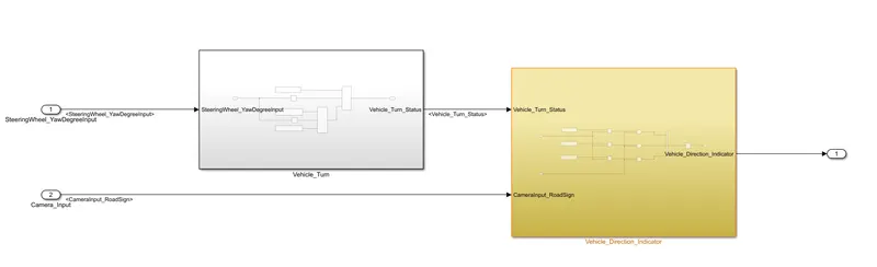
- Here we sub divided the model into two sysrems where Vehicle_turn output signal [Vehicle_Turn_Status] is fed to Vehicle_detection block along with the camera input block.
Inside Vehicle_Turn:
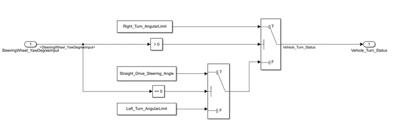
- We have considered the parameter values [Angular Limits] for all right, left and Straight Drive values.
- As mentioned in the requirements right angular limit is connected to a switch where the comparison value fed from another switch[fed with straight drive and left turn values].
- All these values are compared to a constant at switch blocks which acts as threshold to shift the signals accordingly.
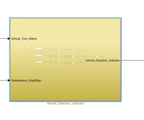
Inside Vehicle_Direction_Indicator:
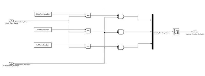
- We have considered the parameter values [Angular Limits] for all right, left and Straight roadsigns.
- As mentioned in the requirements right turn and left turn values are compared against straight drive value in order to decide the indicator that needs to be turned on.
- But here we have 6 signals which are compared with 3 AND blocks which returns 3 signals.
- So to decide which indicator should be turned on after all the process we have used a Signal conversion block to get the final Direction indicator value.
Signal resolver:
- Right click on a signal and then go to properties
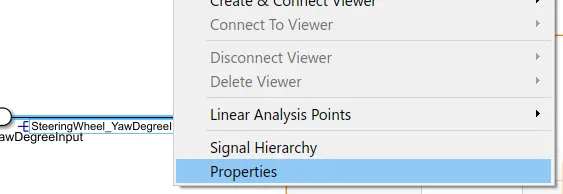
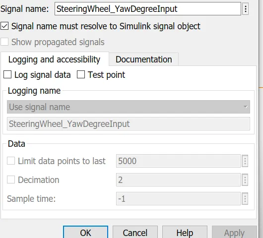
Here we need to enter the signal name and check the "Signal name must resolve" option so that the signal name is visible.
Note: We have to resolve a signal so that it will be easy to identify the signal that is flowing through a line which would be helpful in a complex design.
Requirements:
- Steering wheel input as yaw rate (Signal name: SteeringWheel_YawDegreeInput) is the input for this system.
- This is compared against 3 angular values, one each for left turn, right turn & straight drive (Calibration Values: Right_Turn_AngularLimit, Left_Turn_AngularLimit, Straight_Drive_Steering_Angle) to say which specific direction the steering wheel is turning towards.
- Use switch blocks to compare & develop this requirement. Keep this requirement in a subsystem & output of this requirement is a local signal (Signal Name: Vehicle_Turn_Status).
- Keep this requirement as a separate subsystem. Inputs to this requirement are local signal from requirement 1 (Signal Name: Vehicle_Turn_Status) & an input signal from camera (Signal Name: CameraInput_RoadSign), which confirms the occurrence of a road sign.
- Signal Vehicle_Turn_Status is compared against calibration values (Calibration Values: RightTurn_RoadSign, LeftTurn_RoadSign, Straight_RoadSign), if each of them is found equal, then each of the three corresponding output is compared against the camera input signal,
- Using a logical operator block, only one among them is finally given as output signal (Signal Name: Vehicle_Direction_Indicator).
Linking Requirements:
Here we need to link the requirements that are implemented to the blocks which will inturn helps the engineer to analyse the model easily.
- First create an empty word document and then copy paste the requirements that are already mentioned in the challenge.
- Now select and copy the corresponding requirement[text] of a block and then come back to model.
- Right click on the block and go to requirements where you will find "link to selection in word".
- Now click on it in order to link it, yellow highliting of the block will confirms that the text has been succesfully linked.
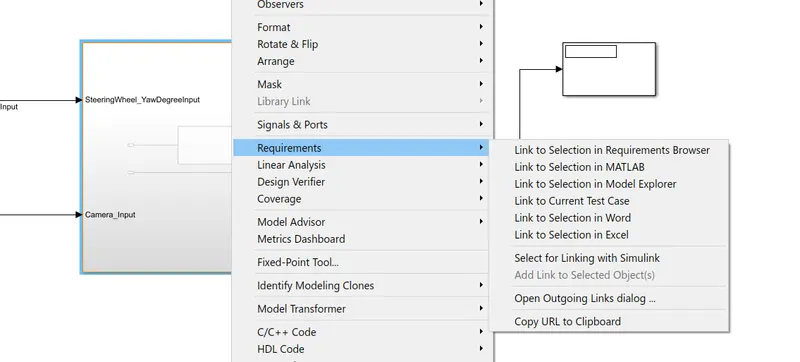
After clicking on link option we can see the text that is linked

Yellow colour of block indicates that it has been linked
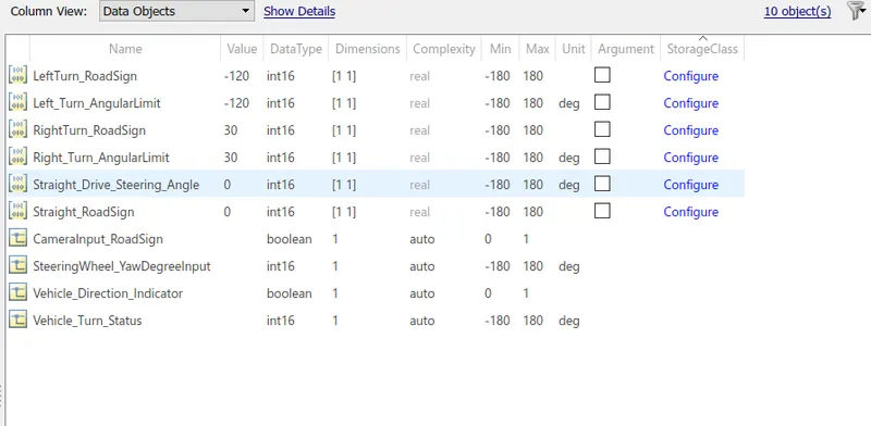
Now the next step is to create an sldd file by mentioning the necessary values that are already given.
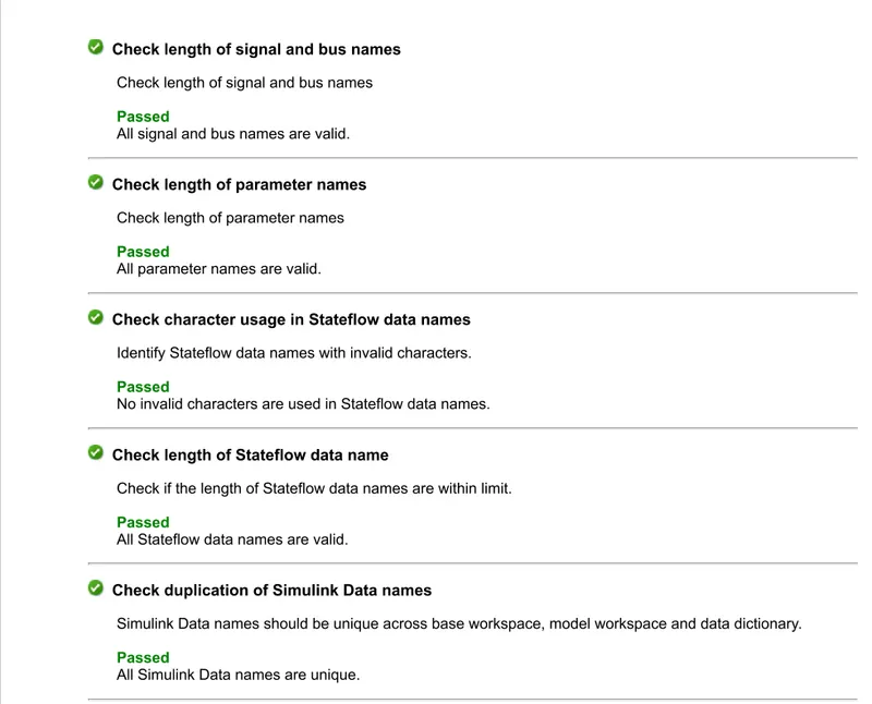
Here we need to run the model Advisor check on the model and generate the report.
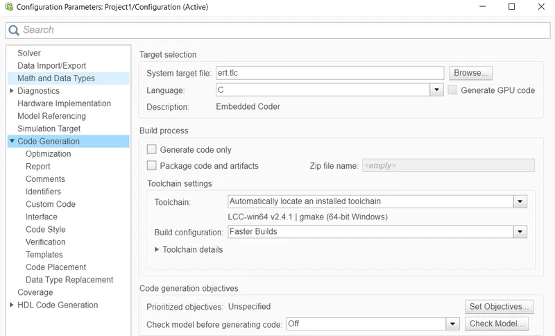
Change the system target file to ert.tlc and click on apply.
Model Advisor can be activated just by right clicking on the modela and then click on it.
Here we will be generating a Advisor report which can be used to analyse the necessary conditions in which it got passed or failed.
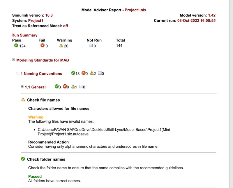
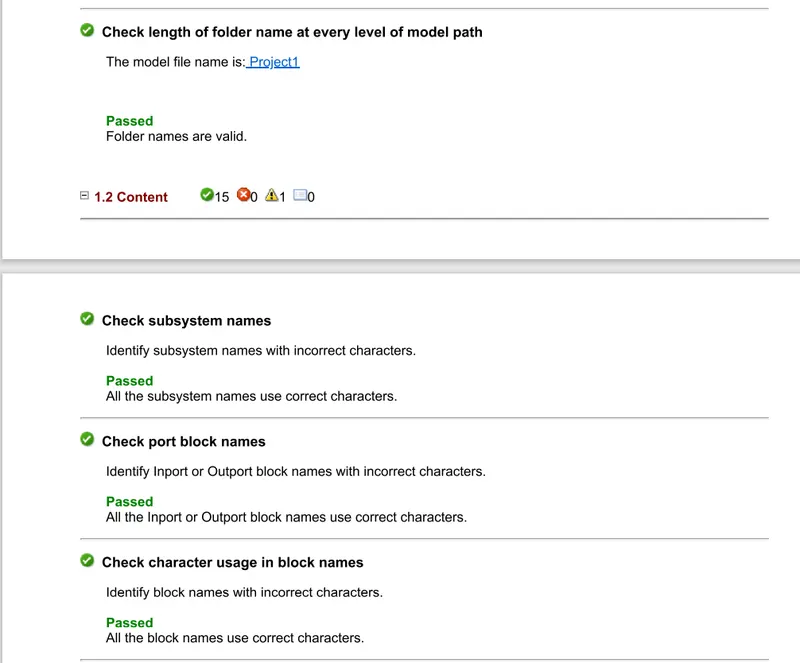
And the embedded code for the model is also done by going to the apps and then clicking on "Embedded Coder".
So now we can conclude that, we have implemented the necessary logics to design the vehicle detection module for an Autonomous Driving.
Necessary code generated files and Model Advisor report is attached below along with the model.