Project 1 (Mini Project on Vehicle Direction Detection
PROCEDURE:
1. The first step in building the model is the understand the requirements and select the right blocks. We will be building a subsystem satisfying the Requirement-1 objectives. We give an input named 'SteeringWheel_YawDegreeInput' which is nothing but the yaw rate of the steering wheel. This value will be compared with 3 angular values for the left turn, right turn, and straight drive to say which specific direction the steering wheel is turning towards and we use the switch blocks to achieve this. This subsystem is shown below.
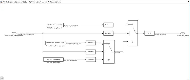
From the above image, we can see that the yaw rate input is compared with the 'Right_Turn_AngularLimit' which is 30. If the input is equal to or greater than 30, then the Right-Turn value will be passed. If not the output of the second switch will be passed. Now, if the input is less than 30, it passes to the second switch condition, here if the input is not equal to 0, then the Left_Turn value is passed, or else the Straight_Drive value will be passed. Here we used 'DATA TYPE CONVERSION' BLOCK for convert int16 to boolean, beacause switch block uses in boolean datatype. Also boolean converted into int16 for required output.
2. We will now build a subsystem satisfying the Requirement-2 objectives. The output of the first subsystem 'Vehicle_Turn_Status' is given as an input along with the 'CameraInput_RoadSign' to the second subsystem. First, the 'Vehicle_Turn_Status' will be compared with calibration values RightTurn_RoadSign, LeftTurn_RoadSign, Straight_RoadSign using the 'compare to constant blocks'. The output of each of these comparison values will go through logical operators 'AND' which will give us the final output called the 'Vehicle_Direction_Indicator'. The subsystem is shown below.
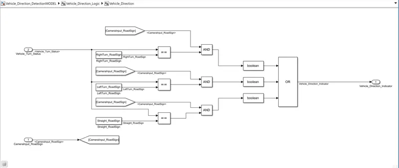
From the above image, we can see that the input from the previous subsystem will be compared with 3 'compare to constant blocks' and the output of which will be compared with the camera input using the logical operators. The AND signal will give us the selected output required and it will be collected using the 'OR' block and also converted input to boolean with the help of Datatype convertion Block. The output can be displayed using the display block. Here we also used 'GoTo' tag and 'From' tag for one input to multiple input supply.
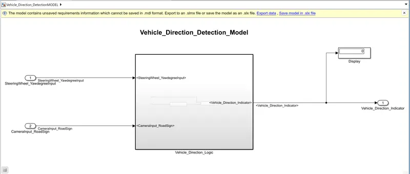
The final model of the 'Vehicle_Direction_Detection' is shown below:
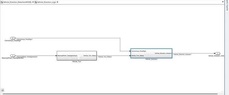
INSIDE OF THE VEHICLE DIRECTION DETECTION LOGIC SUBSYTEM IS SHOWN BELOW:
3. The second objective of the project is to, tag the requirements in the model with the requirement datasheet. We have created an MS word document containing both the 2 requirements as shown below.
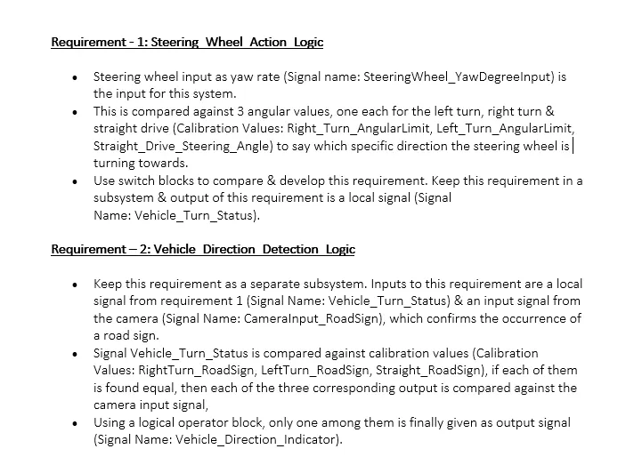
Now, we select the statement that needs to be linked and right-click on the required subsystem shown below. Go to requirements and then click on the 'Link to selection in Word'. A new .slmx file will be created in the path selected and the links will be stored in that file.
The subsystems tagged with their requirements are shown below.
Requirement - 1 is tagged with the Steering_Wheel_Action_Logic subsystem as shown below.
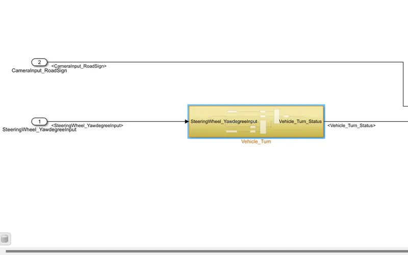
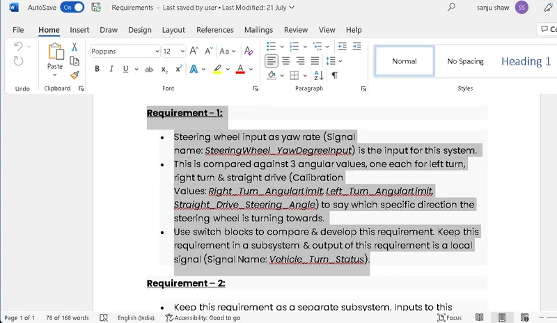
Requirement - 2 is tagged with the Vehicle_Direction_Detection_Logic subsystem as shown below.
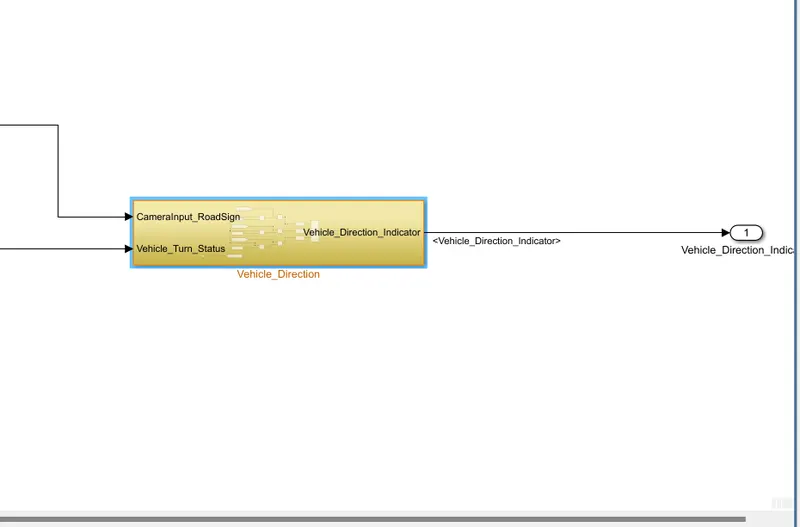
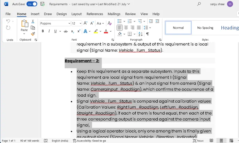
4. Now, we need to create an SLDD file for the same model. The table consisting of all the details regarding the signals and calibration values is given above. We need to first link the model to a data dictionary. We create a new file as shown below.
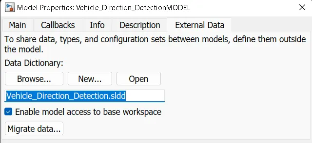
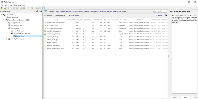
We then open the link and add the given input, output signals and then add the calibration values. The Data dictionary created for the model is shown below.
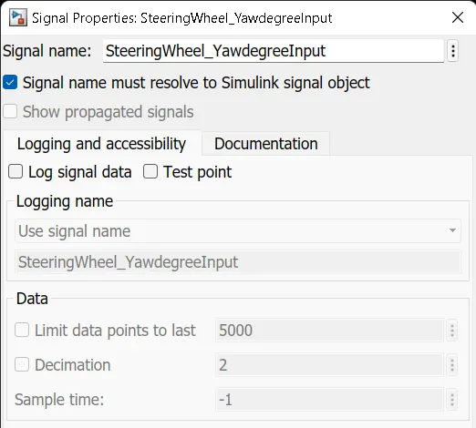
Now that the SLDD file has been created, we can resolve the signal name to the Simulink signal object as shown below.
5. Now, we generate a code for the model which can help us generate an S-function block which is helpful in the testing of the model. We first change the format of the model from grt. tlc to ert. tlc as shown in the image below.
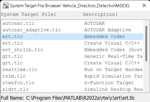
- Configuration Parameter Setting:
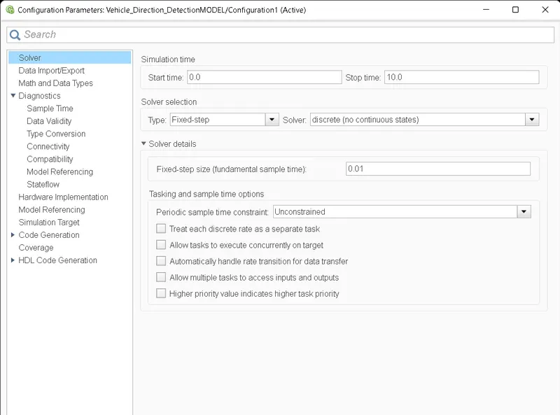
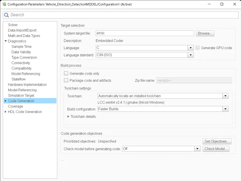
after that we generate code through the proccess of right click on the main subsystem then go to the 'Block Parameter(Subsytem) and click on treat as a atomic unit.
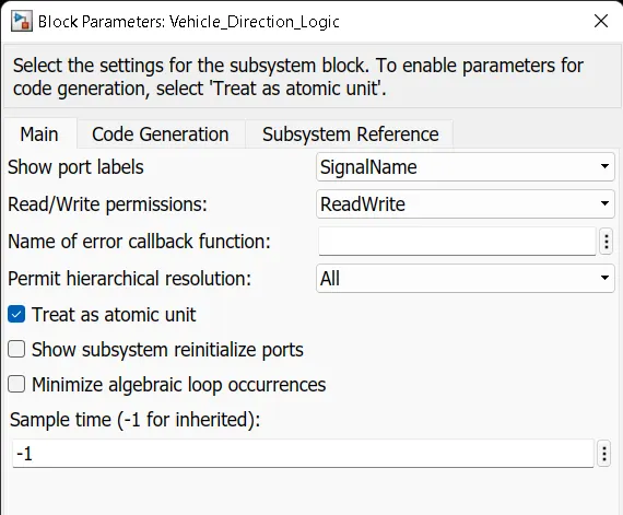
Then we again right click on main subsystem and go to the 'C/C++code and generate S-Function Block and after some times it generate the code and its shown below:
* $FID.WWA.002258$
*/
Subsystem_Y.Right_Turn_Output = 1.0;
/* Outport: '<Root>/<Round_Turn_Output>' incorporates:
* Constant: '<S7>/Constant3'
*
* Block description for '<S7>/Constant3':
* $FID.WWA.002260$
*/
Subsystem_Y.Round_Turn_Output = 1.0;
break;
case 5:
/* Outport: '<Root>/<Left_Turn_Output>' incorporates:
* Constant: '<S8>/Constant'
*
* Block description for '<S8>/Constant':
* $FID.WWA.002353$
*/
Subsystem_Y.Left_Turn_Output = 1.0;
/* Outport: '<Root>/<Right_Turn_Output>' incorporates:
* Constant: '<S8>/Constant1'
*
* Block description for '<S8>/Constant1':
* $FID.WWA.002354$
*/
Subsystem_Y.Right_Turn_Output = 1.0;
/* Outport: '<Root>/<Round_Turn_Output>' incorporates:
* Constant: '<S8>/Constant3'
*
* Block description for '<S8>/Constant3':
* $FID.WWA.002356$
*/
Subsystem_Y.Round_Turn_Output = 1.0;
break;
case 6:
/* Outport: '<Root>/<Left_Turn_Output>' incorporates:
* Constant: '<S9>/Constant'
*
* Block description for '<S9>/Constant':
* $FID.WWA.002342$
*/
Subsystem_Y.Left_Turn_Output = 1.0;
/* Outport: '<Root>/<Right_Turn_Output>' incorporates:
* Constant: '<S9>/Constant1'
*
* Block description for '<S9>/Constant1':
* $FID.WWA.002343$
*/
Subsystem_Y.Right_Turn_Output = 1.0;
/* Outport: '<Root>/<Round_Turn_Output>' incorporates:
* Constant: '<S9>/Constant3'
*
* Block description for '<S9>/Constant3':
* $FID.WWA.002345$
*/
Subsystem_Y.Round_Turn_Output = 1.0;
break;
case 7:
/* Outport: '<Root>/<Left_Turn_Output>' incorporates:
* Constant: '<S10>/Constant'
*
* Block description for '<S10>/Constant':
* $FID.WWA.002604$
*/
Subsystem_Y.Left_Turn_Output = 0.0;
/* Outport: '<Root>/<Right_Turn_Output>' incorporates:
* Constant: '<S10>/Constant1'
*
* Block description for '<S10>/Constant1':
* $FID.WWA.002605$
*/
Subsystem_Y.Right_Turn_Output = 1.0;
/* Outport: '<Root>/<Round_Turn_Output>' incorporates:
* Constant: '<S10>/Constant3'
*
* Block description for '<S10>/Constant3':
* $FID.WWA.002607$
*/
Subsystem_Y.Round_Turn_Output = 0.0;
break;
case 8:
/* Outport: '<Root>/<Left_Turn_Output>' incorporates:
* Constant: '<S11>/Constant'
*
* Block description for '<S11>/Constant':
* $FID.WWA.002287$
*/
Subsystem_Y.Left_Turn_Output = 0.0;
/* Outport: '<Root>/<Right_Turn_Output>' incorporates:
* Constant: '<S11>/Constant1'
*
* Block description for '<S11>/Constant1':
* $FID.WWA.002288$
*/
Subsystem_Y.Right_Turn_Output = 1.0;
/* Outport: '<Root>/<Round_Turn_Output>' incorporates:
* Constant: '<S11>/Constant3'
*
* Block description for '<S11>/Constant3':
* $FID.WWA.002290$
*/
Subsystem_Y.Round_Turn_Output = 0.0;
break;
case 9:
/* Outport: '<Root>/<Left_Turn_Output>' incorporates:
* Constant: '<S12>/Constant'
*
* Block description for '<S12>/Constant':
* $FID.WWA.002589$
*/
Subsystem_Y.Left_Turn_Output = 0.0;
/* Outport: '<Root>/<Right_Turn_Output>' incorporates:
* Constant: '<S12>/Constant1'
*
* Block description for '<S12>/Constant1':
* $FID.WWA.002590$
*/
Subsystem_Y.Right_Turn_Output = 1.0;
/* Outport: '<Root>/<Round_Turn_Output>' incorporates:
* Constant: '<S12>/Constant3'
*
* Block description for '<S12>/Constant3':
* $FID.WWA.002592$
*/
Subsystem_Y.Round_Turn_Output = 1.0;
break;
case 10:
/* Outport: '<Root>/<Left_Turn_Output>' incorporates:
* Constant: '<S4>/Constant'
*
* Block description for '<S4>/Constant':
* $FID.WWA.002297$
*/
Subsystem_Y.Left_Turn_Output = 1.0;
/* Outport: '<Root>/<Right_Turn_Output>' incorporates:
* Constant: '<S4>/Constant1'
*
* Block description for '<S4>/Constant1':
* $FID.WWA.002298$
*/
Subsystem_Y.Right_Turn_Output = 1.0;
/* Outport: '<Root>/<Round_Turn_Output>' incorporates:
* Constant: '<S4>/Constant3'
*
* Block description for '<S4>/Constant3':
* $FID.WWA.002300$
*/
Subsystem_Y.Round_Turn_Output = 1.0;
break;
default:
/* Outport: '<Root>/<Left_Turn_Output>' incorporates:
* Constant: '<S2>/Constant'
*
* Block description for '<S2>/Constant':
* $FID.WWA.002282$
*/
Subsystem_Y.Left_Turn_Output = 0.0;
/* Outport: '<Root>/<Right_Turn_Output>' incorporates:
* Constant: '<S2>/Constant1'
*
* Block description for '<S2>/Constant1':
* $FID.WWA.002283$
*/
Subsystem_Y.Right_Turn_Output = 0.0;
/* Outport: '<Root>/<Round_Turn_Output>' incorporates:
* Constant: '<S2>/Constant3'
*
* Block description for '<S2>/Constant3':
* $FID.WWA.002285$
*/
Subsystem_Y.Round_Turn_Output = 0.0;
break;
}
/* End of MultiPortSwitch generated from: '<S1>/Multiport Switch' */
/* End of Outputs for SubSystem: '<Root>/Subsystem' */
}
/* Model initialize function */
void Subsystem_initialize(void)
{
/* (no initialization code required) */
}
/* Model terminate function */
void Subsystem_terminate(void)
{
/* (no terminate code required) */
}
/*
* File trailer for generated code.
*
* [EOF]
*/