Project 1 (Mini Project on Vehicle Direction Detection
Identifying the direction of the vehicle is one of the important & diverse features in Autonomous driving & Advanced Driver Assistance Features. This particular sub-feature of identifying the direction of vehicle is basically identifying the direction the vehicle is taking based on the camera input.
Objective of Project:
- Development of MATLAB Simulink model as per requirement.
- Tag the requirements to the simulink model, tagging requirement 1 & requirement 2 to their corresponding subsystems is fine.
- MBD compliant changes, Data Dictionary creation & code generation is added advantage, and that is not scope of this project.
Task:
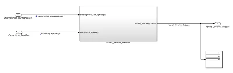
- Steering wheel input as yaw rate (Signal name: SteeringWheel_YawDegreeInput) is the input for this system. & input signal from camera (Signal Name: CameraInput_RoadSign), which confirms the occurrence of a road sign.
- camera reads the road sign and stores them in its memory unique value left turn, right turn and straight drive.
- the output of the system is Using a logical operator block, only one among them is finally given as output signal (Signal Name: Vehicle_Direction_Indicator).
Model development:
The main subsystem of the model is vehicle_direction_detection with two input SteeringWheel_YawDegreeInput, CameraInput_RoadSign and one output signal Vehicle_Direction_Indicator.
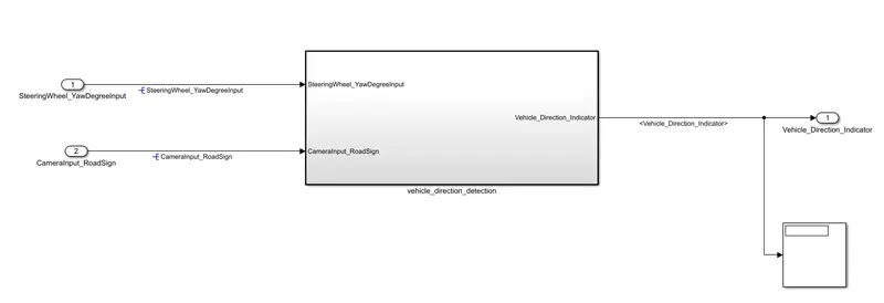
The vehicle_direction_detection subsystem divide two more subsystem which is Requirement1 and Requirement2.
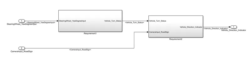
Requirement1 subsystem:
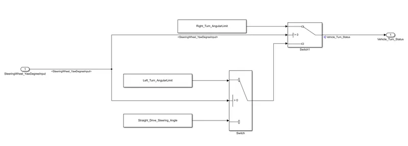
- steering wheel input as yaw rate Signal name: SteeringWheel_YawDegreeInput is the input of the system.
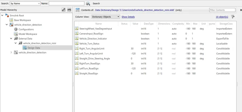
- the input is compared against three angular value Right_Turn_AngularLimit, Left_Turn_AngularLimit, Straight_Drive_Steering_Angle to give the specific direction of steering wheel is turning towards.
- using switch block to compare and develop the requirement and the output of this requirement is local signal Vehicle_Turn_Status.
Requirement2 subsystem:
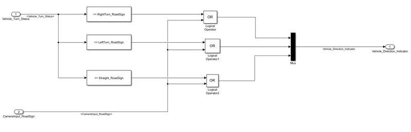
- requirement 2 is seperate subsystem. input of requirement 2 susbsystem is Vehicle_Turn_Status and input signal from the camera is CameraInput_RoadSign which is confirms the occurrance of road sign.
- input signal Vehicle_Turn_Status is compared against calibration values RightTurn_RoadSign, LeftTurn_RoadSign, Straight_RoadSign each of them is found equal, then each of three corresponding output compared against camerainput_roadsign signal.
- using logical operator OR block only one amoung them finally given as output signal Vehicle_Direction_Indicator.
Simulink data dictionary file (SLDD):
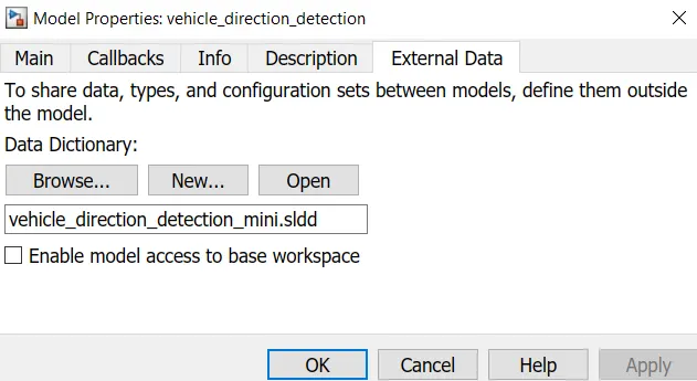
a SLDD file is created that contains input and output signals which used in the model. creation of SLDD file click the modelling and go to the model properties then choose the external data and create new data dictionary.
OUTPUT:
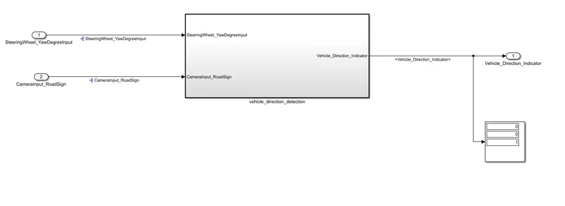
straight turn:
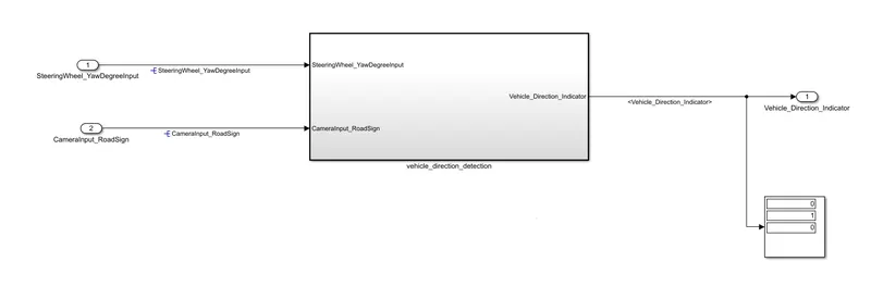
Left turn:
Right turn:
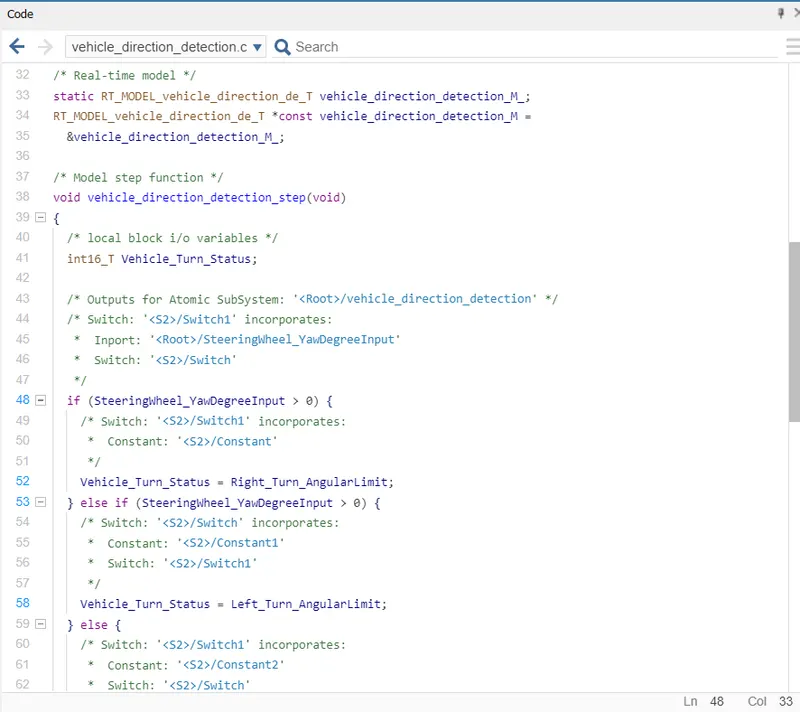
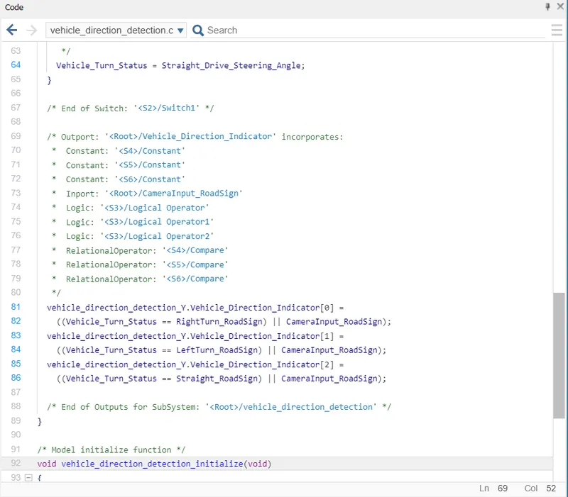
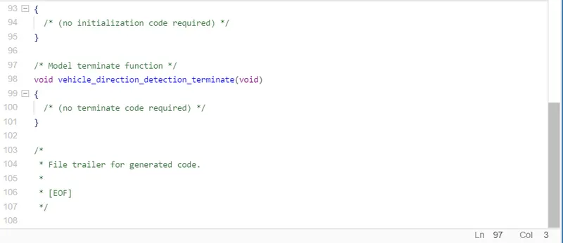
Generate code:
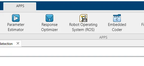
- genration of code of the following simulink model, select apps in matlab window and select embedded coder.
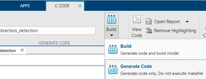
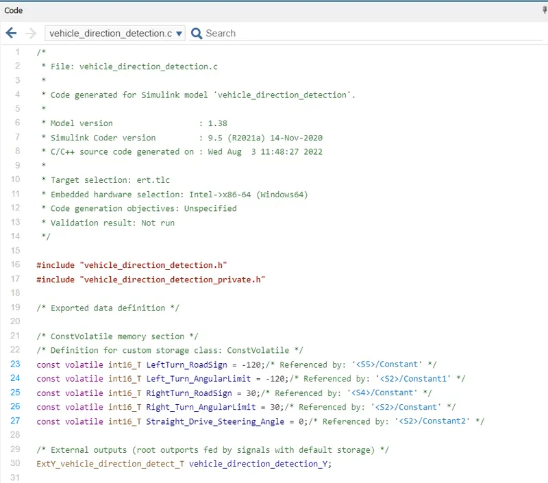
- after selecting the embedded coder the c code window will be open, in c code select the build option and code will be generated.
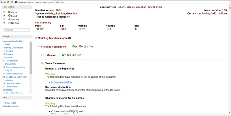
Model advisior check:
In model advisior tool in simulink to see whether the developed model meets the modelling standard for MAAB.
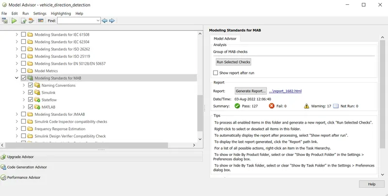
after running the selected checks of model advisior generate the report.
Conclusion:
sucessfully making model from the given requirement input data and generating model advisor report and generated code.