Vehicle Direction Detection (Mini Project)
OBJECTIVE:
- To develop a MATLAB Simulink Model as per the following requirements:
- Requirement 1:
- Steering wheel input as yaw rate (Signal name: SteeringWheel_YawDegreeInput) is the input for this system.
- This is compared against 3 angular values, one each for left turn, right turn & straight drive (Calibration Values: Right_Turn_AngularLimit, Left_Turn_AngularLimit, Straight_Drive_Steering_Angle) to say which specific direction the steering wheel is turning towards.
- Use switch blocks to compare & develop this requirement. Keep this requirement in a subsystem & output of this requirement is a local signal (Signal Name: Vehicle_Turn_Status).
- Requirement 1:
- Requirement 2:
- Keep this requirement as a separate subsystem. Inputs to this requirement are local signal from requirement 1 (Signal Name: Vehicle_Turn_Status) & an input signal from camera (Signal Name: CameraInput_RoadSign), which confirms the occurrence of a road sign.
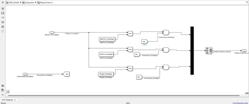
- Signal Vehicle_Turn_Status is compared against calibration values (Calibration Values: RightTurn_RoadSign, LeftTurn_RoadSign, Straight_RoadSign), if each of them is found equal, then each of the three corresponding output is compared against the camera input signal,
- Using a logical operator block, only one among them is finally given as output signal (Signal Name: Vehicle_Direction_Indicator).
- To tag the requirements to the Simulink Model via tagging the requirements (1 & 2) to their corresponding subsystems.
- To create a Data Dictionary, generate Code and make MBD Compliant Changes to the Model.
- Signals and Parameters for creating Data Dictionary:
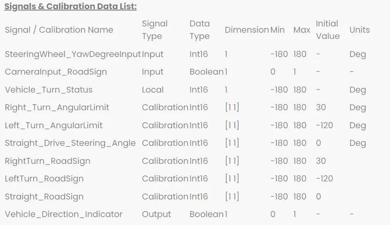
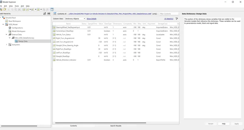
- While creating the Data Dictionary, to set the Storage Class for Input Signals to ‘ImportedExtern’, Storage Class for Output Signals to ‘Export to File’, storage Class for local signals to ‘localizable’ and Storage Class for calibration Signals to ‘Const.’.
- To set the Sample Time for all signals to 0.01 s.
GENERAL OVERVIEW:
Advanced Driver Assistance Systems (ADAS) are systems which are primarily designed to help the Driver of a vehicle. These Systems are primarily used to improve safety as most Road accidents occur due to human error.
ADAS relies on inputs from several sources such as lidar, radar, cameras and vehicle CAN data. Safety features are designed to alert the driver to potential problems, or to avoid collisions by implementing safeguards. In some cases, this means taking control of the vehicle from the Driver.
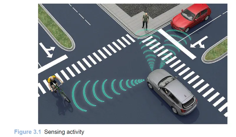
ADAS features can, for example, switch on lights, provide adaptive cruise control and collision avoidance, incorporate traffic warnings, alert the driver to other vehicles and dangers, warn if lane departure is detected or even initiate automated lane guidance. Cameras are used to see in blind spots.
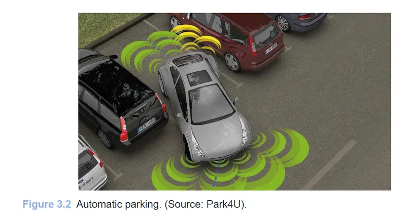
Many modern vehicles now have systems such as electronic stability control, anti-lock brakes, lane departure warning, adaptive cruise control and traction control. All these systems can be affected by mechanical alignment. For this reason, correct repairs, adjustments and servicing are essential.
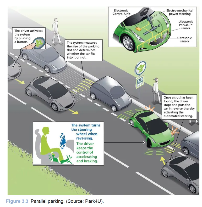
Some examples of Advanced Driver Assistance Systems are as follows:
- Adaptive Cruise Control
- Adaptive Light Control
- Anti-Lock Braking System
- Automatic Parking
- Blind Spot Monitor
- Collision Avoidance
- Collision Warning
- Driver Drowsiness Detection
- Electric Vehicle Warning Sounds
- Emergency Driver Assistant
- Glare-Free High Beam and Pixel Light
- Lane Change Assistance
- Lane Departure Warning
- Navigation System with Traffic Information
- Night Vision
- Parking Sensor
- Pedestrian Protection
- Rain Sensor
- Surround View
- Traffic Sign Recognition
- Tyre Pressure Monitoring
- Vehicle Direction Determination/Detection
Vehicle Direction Detection:
Identifying the direction of the vehicle is one of the important & diverse features in Autonomous driving & Advanced Driver Assistance Features. This particular sub-feature of identifying the direction of vehicle is basically identifying the direction the vehicle is taking based on the camera input.
Camera reads the road signs & stores into its memory with unique values for left turn, right turn & straight drive. Depending on the direction it is taking, final indication is given to the driver – as an indication if he is driving in the recommended direction or not.
Vehicle Direction Determination can also be coupled along - side features like GPS systems to identify whether the vehicle is reaching its destination in an optimized manner. This sub feature can also be used along with Lane Detection, Highway Warning, Ramp Entry / Exit in Wrong Way Detection etc
STEPS FOR MODELLING AS PER THE GIVEN REQUIREMENTS & DIRECTIONS:
Step 1: Creating the Data Dictionary:
- The Data Dictionary for the Model is created as per definition in the Question.
- Signals and Parameters definitions for the Model as per definition in the Question:
- Signals and Parameters defined in the Data Dictionary:
Step 2: Modelling for Requirement 1:
- Steering Wheel Orientation taken as input in the form of Yaw Rate of the Vehicle. This input Signal is represented by the Signal Name: SteeringWheel_YawDegreeInput defined in the Data Dictionary Linked to the Model.
- This input Signal is compared against the Calibrated Values of 3 basic Directions for Driving: Left Turn, Right Turn and Straight Drive. The Calibrated Values for Left Turn Angular Limit, Right Turn Angular Limit and Straight Drive Steering Angle is defined in the Data Dictionary with names Right_Turn_AngularLimit, Left_Turn_AngularLimit, Straight_Drive_Steering_Angle repectively. This Comparison is done to identify in which direction the Vehicle is moving.
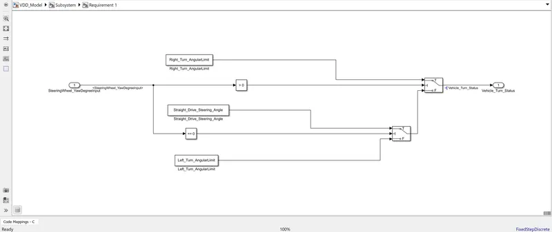
- The Comparison is done using ‘Compare to 0’ Blocks and Switch Blocks. The Logic followed for modelling this requirement is as follows:
- If the Yaw Rate of the Vehicle (Steering Wheel Orientation Input) is greater than 0 (Angle of Vehicle is assumed to be positive on Right Hand Side), then the Vehicle Turn Status (signal defined in the Data Dictionary as Vehicle_Turn_Status) is towards Right (parameter defined in the Data Dictionary as Right_Turn_Angular_Limit).
- If the Yaw Rate of the Vehicle (Steering Wheel Orientation Input) is equal to 0 (Angle of Vehicle is assumed to be positive on Right Hand Side), then the Vehicle Turn Status (signal defined in the Data Dictionary as Vehicle_Turn_Status) is Straight (parameter defined in the Data Dictionary as Straight_Drive_Steering_Angle).
- If the Yaw Rate of the Vehicle (Steering Wheel Orientation Input) is lesser than 0 (Angle of Vehicle is assumed to be positive on Right Hand Side), then the Vehicle Turn Status (signal defined in the Data Dictionary as Vehicle_Turn_Status) is towards Left (parameter defined in the Data Dictionary as Left_Turn_Angular_Limit).
- Model of Requirement 1:
Step 3: Modelling for Requirement 2:
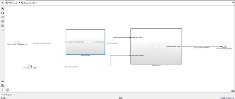
- The Required Output (Vehicle_Turn_Status) Signal from the ‘Requirement 1’ Subsystem is now fed as an input to the ‘Requirement 2 Subsystem’ along with the Camera Road Sign Input (defined in Data Dictionary as CameraInput_RoadSign).
- This Subsystem: ‘Requirement 2’ will be used to compare the incoming Vehicle Turn Status (defined as Vehicle_Turn_Status) with their respective (in terms of Direction) Road Sign Values. If the Vehicle Turn Status is found equal to the its respective Direction Calibration Value (stored ), then the corresponding Output Signal is compared with the Camera Input Signal and if the Camera Input Signal is ON , then the corresponding Vehicle Direction(Signal defined as Vehicle_Direction_Indicator in the Data Dictionary) will be indicated in the Output End.
- Model for Requirement 2:
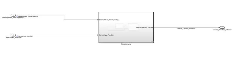
- Subsystem Model housing the Requirements:
- Main Model:
Step 4: Tagging the Requirements:
- The Requirements as per description in the question have been modelled inside Subsystem.
- A Word File has been made in which the Requirements have been described.
- The Heading of the Part describing their respective requirements or the Entire Requirement Description is selected in the Word File.
- After selection of the required part, the subsystem representing the relevant Requirement is right-clicked on.
- On right clicking the Subsystem, the option Requirements -> Link to Selection in Word is done.
- The Requirement(s) Subsystems are tagged with their respective descriptions in the Word File.
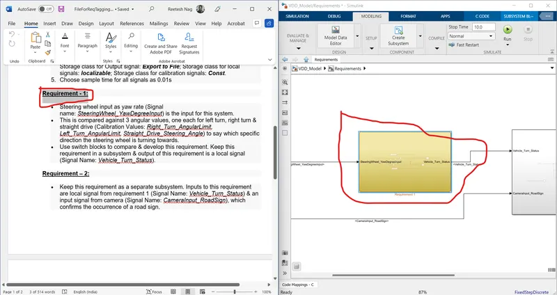
Tagging of Requirement 1 in the Model
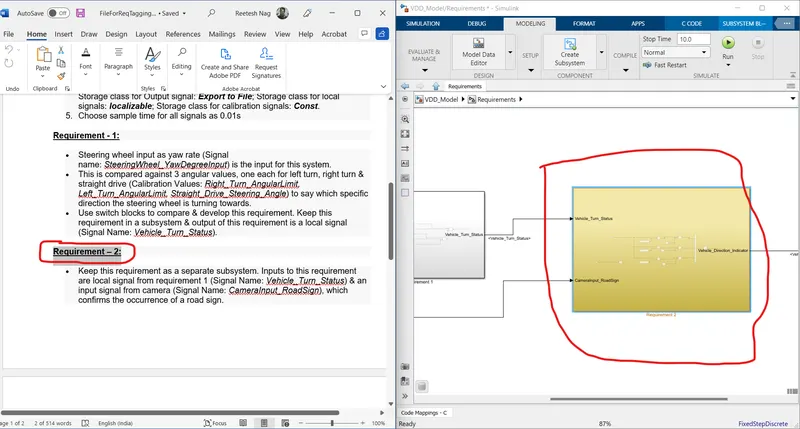
Tagging of Requirement 2 in the Model
Step 6: MBD Compliant Changes:
- Under the Modelling Tab, the ‘Model Advisor’ button is clicked. The ‘System Selector-Model Advisor’ Window opens. The Main System under the System Hierarchy is selected and the OK Button is clicked.
- In the subsequent Window that opens, Under ‘By Task’ section, only ‘Modelling Standards for MAB’ is selected while rest other options are deselected. The ‘By Product’ section is also deselected.
- On selecting the ‘Modelling Standards for MAB’ section, the ‘Run Selected Checks’ Button is clicked and then Continue Button is pressed.
- The Summary Section is used to evaluate the compliancy of the Model according to MAB Modelling Standards.
- The Generate Report Button is clicked.
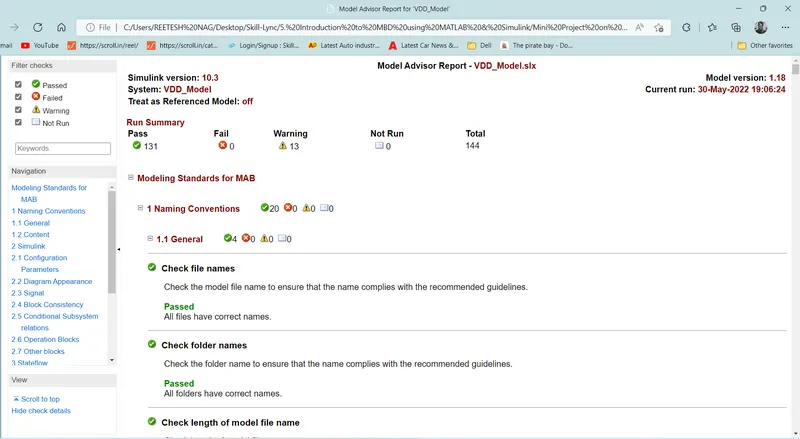
Model Advisor Report Generated
Step 7: Code Generation:
- The Code can be generated clicking on the Apps Pane -> Embedded Coder.
- The C CODE Pane will be visible after ‘Embedded Coder’ App. Under the C CODE Pane, the Build Button is clicked. The Code gets generated.
- Picture of Code Generated in Simulink:
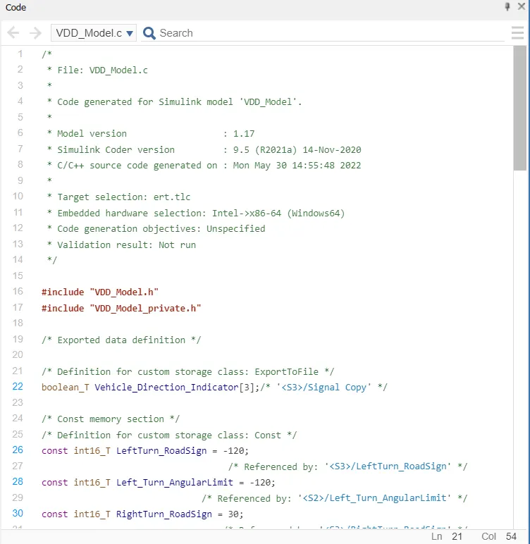
- C Code Generated:
/*
 * File: VDD_Model.c
 *
 * Code generated for Simulink model 'VDD_Model'.
 *
 * Model version                  : 1.17
 * Simulink Coder version         : 9.5 (R2021a) 14-Nov-2020
 * C/C++ source code generated on : Mon May 30 14:55:48 2022
 *
 * Target selection: ert.tlc
 * Embedded hardware selection: Intel->x86-64 (Windows64)
 * Code generation objectives: Unspecified
 * Validation result: Not run
 */

#include "VDD_Model.h"
#include "VDD_Model_private.h"

/* Exported data definition */

/* Definition for custom storage class: ExportToFile */
boolean_T Vehicle_Direction_Indicator[3];/* '/Signal Copy' */

/* Const memory section */
/* Definition for custom storage class: Const */
const int16_T LeftTurn_RoadSign = -120;
                                   /* Referenced by: '/LeftTurn_RoadSign' */
const int16_T Left_Turn_AngularLimit = -120;
                              /* Referenced by: '/Left_Turn_AngularLimit' */
const int16_T RightTurn_RoadSign = 30;
                                  /* Referenced by: '/RightTurn_RoadSign' */
const int16_T Right_Turn_AngularLimit = 30;
                             /* Referenced by: '/Right_Turn_AngularLimit' */
const int16_T Straight_Drive_Steering_Angle = 0;
                       /* Referenced by: '/Straight_Drive_Steering_Angle' */
const int16_T Straight_RoadSign = 0;
                                   /* Referenced by: '/Straight_RoadSign' */

/* Real-time model */
static RT_MODEL_VDD_Model_T VDD_Model_M_;
RT_MODEL_VDD_Model_T *const VDD_Model_M = &VDD_Model_M_;

/* Model step function */
void VDD_Model_step(void)
{
  /* local block i/o variables */
  int16_T Vehicle_Turn_Status;

  /* Outputs for Atomic SubSystem: '/Subsystem' */
  /* Switch: '/Switch' incorporates:
   *  Constant: '/Constant'
   *  Constant: '/Constant'
   *  Inport: '/SteeringWheel_YawDegreeInput'
   *  RelationalOperator: '/Compare'
   *  RelationalOperator: '/Compare'
   *  Switch: '/Switch1'
   */
  if (SteeringWheel_YawDegreeInput > 0) {
    /* Switch: '/Switch' incorporates:
     *  Constant: '/Right_Turn_AngularLimit'
     */
    Vehicle_Turn_Status = Right_Turn_AngularLimit;
  } else if (SteeringWheel_YawDegreeInput == 0) {
    /* Switch: '/Switch1' incorporates:
     *  Constant: '/Straight_Drive_Steering_Angle'
     *  Switch: '/Switch'
     */
    Vehicle_Turn_Status = Straight_Drive_Steering_Angle;
  } else {
    /* Switch: '/Switch' incorporates:
     *  Constant: '/Left_Turn_AngularLimit'
     *  Switch: '/Switch1'
     */
    Vehicle_Turn_Status = Left_Turn_AngularLimit;
  }

  /* End of Switch: '/Switch' */

  /* SignalConversion: '/Signal Copy' incorporates:
   *  Constant: '/LeftTurn_RoadSign'
   *  Constant: '/RightTurn_RoadSign'
   *  Constant: '/Straight_RoadSign'
   *  Inport: '/CameraInput_RoadSign'
   *  Logic: '/AND'
   *  Logic: '/AND1'
   *  Logic: '/AND2'
   *  RelationalOperator: '/Equal'
   *  RelationalOperator: '/Equal1'
   *  RelationalOperator: '/Equal2'
   */
  Vehicle_Direction_Indicator[0] = ((Vehicle_Turn_Status == RightTurn_RoadSign) &&
    CameraInput_RoadSign);
  Vehicle_Direction_Indicator[1] = ((Vehicle_Turn_Status == LeftTurn_RoadSign) &&
    CameraInput_RoadSign);
  Vehicle_Direction_Indicator[2] = ((Vehicle_Turn_Status == Straight_RoadSign) &&
    CameraInput_RoadSign);

  /* End of Outputs for SubSystem: '/Subsystem' */
}

/* Model initialize function */
void VDD_Model_initialize(void)
{
  /* (no initialization code required) */
}

/* Model terminate function */
void VDD_Model_terminate(void)
{
  /* (no terminate code required) */
}

/*
 * File trailer for generated code.
 *
 * [EOF]
 */
RESULT:
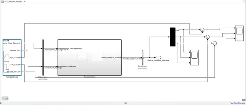
- A Test Harness Model for the Requirements Subsystem (Main Subsystem of the Model) is created and a Signal Builder is given as Input Source for the Subsystem.
- NOTE: Before simulating the Test Harness Model, the Sample Time of the Output Signal(Vehicle_Direction_Indicator) is converted to -1 for successful Simulation. The Sample Time for all signals was asked to be kept as 0.01 as per the Problem Objective.
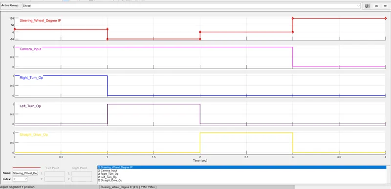
- In the Test Harness Model, the Test Cases which were separately defined in an Excel File is exported to the Signal Builder Block.
- Test Cases defined in an Excel File:
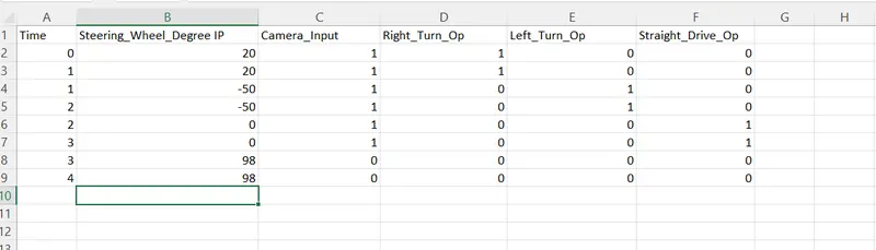
- Test cases Exported to Signal Builder Block of Test Harness Model:
- The Outputs on simulating the Model and the Outputs from the Test Cases are compared using the Sum Blocks and the Scope block to establish the validity of the Model:
- The Results on Simulating the Model and Observing the Differences between the Outputs on simulating the Model and the Outputs loaded as Tests Cases in the Signal Builder:
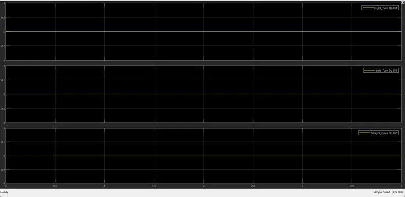
- Hence the Validity of the Model as per the Test Cases have been established.