Project 1 (Mini Project on Vehicle Direction Detection
Objective:
- The main objective of this project is to develop an MBD Simulink model for Vehicle Direction Determination as per the requirement.
- Link the requirement to the Simulink model; tagging Requirement 1 & Requirement 2 to their respective subsystems.
- Generate the Data Dictionary, Code generation, MIL test & SIL test.
Introduction:
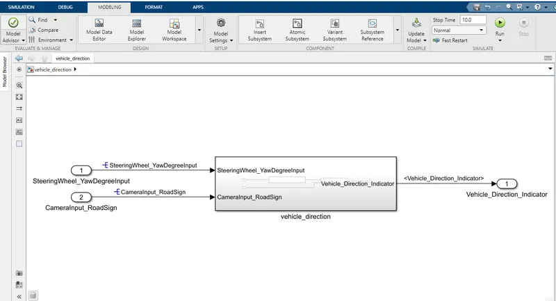
- Steering wheel input as yaw rate (Signal name: SteeringWheel_YawDegreeInput) and an input signal from the camera (Signal Name: CameraInput_RoadSign) are the two input signals to the model.
-
The camera reads the road signs & stores them into its memory with unique values for a left turn, right turn & or straight drive. Depending on the direction it is taking, the final indication is given to the driver – as an indication if he is driving in the recommended direction or not.
- The output signal (Signal Name: Vehicle_Direction_Indicator) is the boolean value that determines the vehicle direction.
Simulink model:
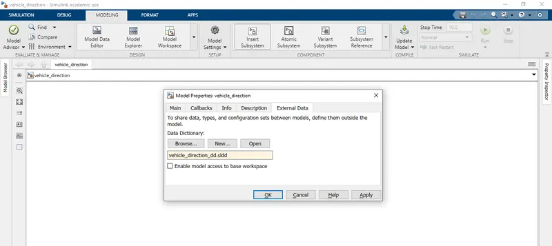
Create the data dictionary file as shown below.
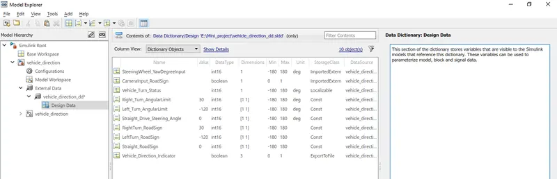
Signals & calibration data are stored in the data dictionary file as per the requirements & saved it.
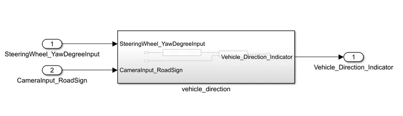
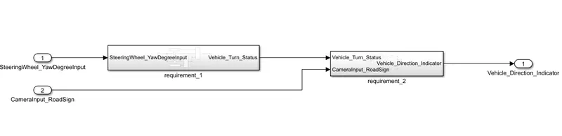
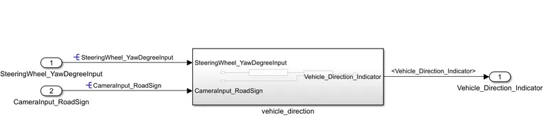
2 subsystems of requirement 1 & requirement 2 are created inside the vehicle direction subsystem model as shown below.
Requirement - 1:
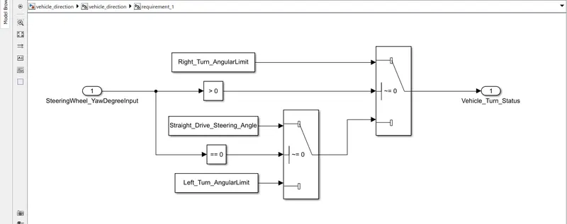
- Steering wheel input as yaw rate (Signal name: SteeringWheel_YawDegreeInput) is the input for this system.
- This is compared against 3 angular values, one each for a left turn, right turn & straight drive (Calibration Values: Right_Turn_AngularLimit, Left_Turn_AngularLimit, Straight_Drive_Steering_Angle) to say which specific direction the steering wheel is turning towards.
- Use switch blocks to compare & develop this requirement. Keep this requirement in a subsystem & the output of this requirement is a local signal (Signal Name: Vehicle_Turn_Status).
Requirement – 2:
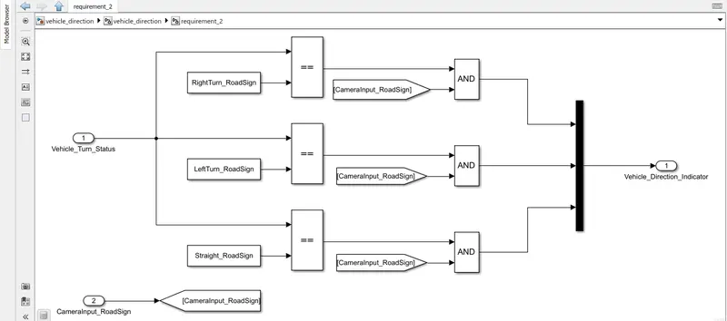
- Keep this requirement as a separate subsystem. Inputs to this requirement are a local signal from requirement 1 (Signal Name: Vehicle_Turn_Status) & an input signal from the camera (Signal Name: CameraInput_RoadSign), which confirms the occurrence of a road sign.
- Signal Vehicle_Turn_Status is compared against calibration values (Calibration Values: RightTurn_RoadSign, LeftTurn_RoadSign, Straight_RoadSign), if each of them is found equal, then each of the three corresponding outputs is compared against the camera input signal,
- Using a logical operator block, only one among them is finally given as the output signal (Signal Name: Vehicle_Direction_Indicator).
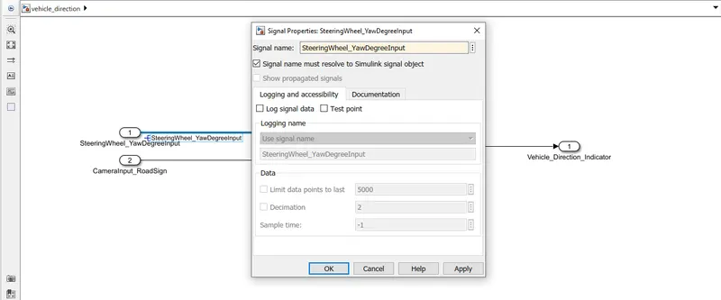
Signal resolving and propagation are done as shown below throughout the model. For input/output initial signal line signal is resolved once, then it can be propagated.
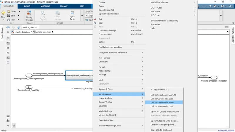
Link the requirement 1 & requirement to the required word file as shown below.
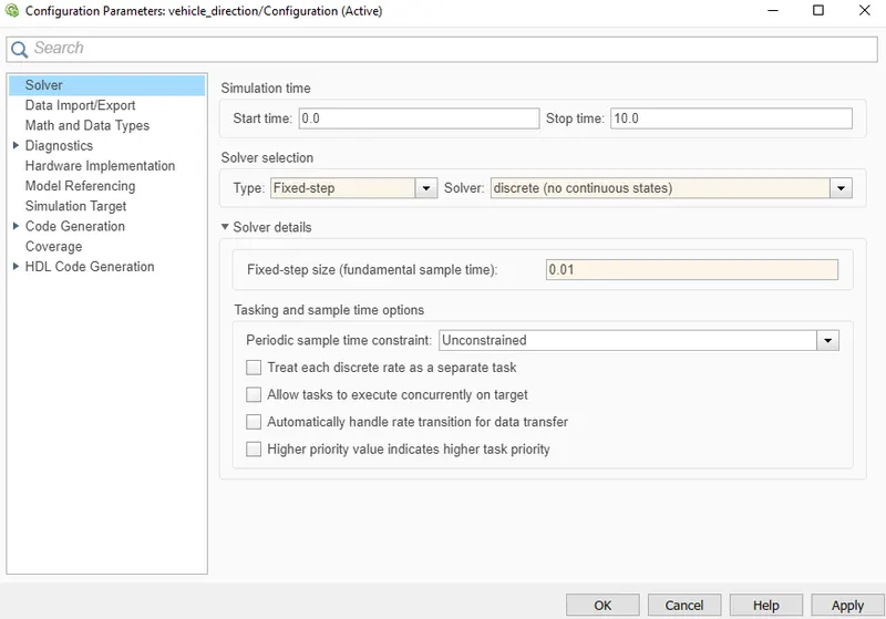
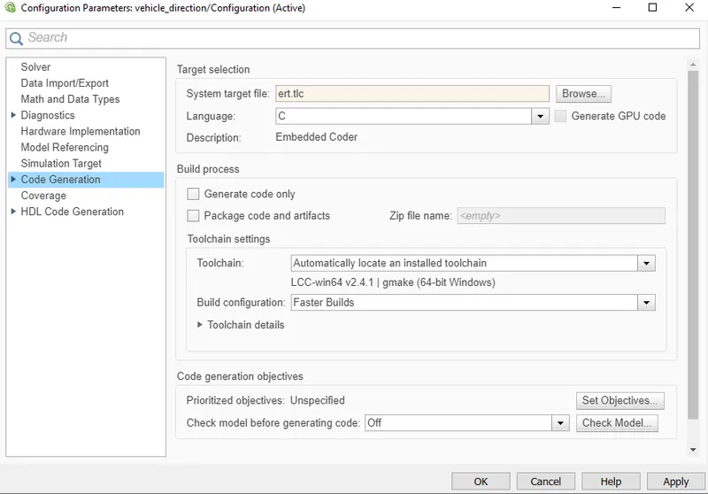
Go to model settings and change the solver type to fixed step, discrete solver, and sample time to 0.01 sec. And code generation to the embedded coder.
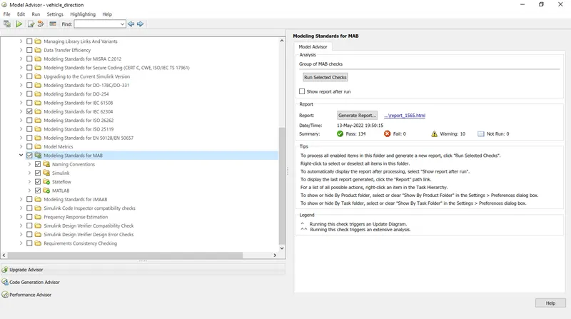
To do the MAB test go to the model advisor menu.
Select the Modeling standards for MAB and click run selected checks. And make sure the number of fails is zero.
To generate the code, go to the embedded coder in the apps tab.
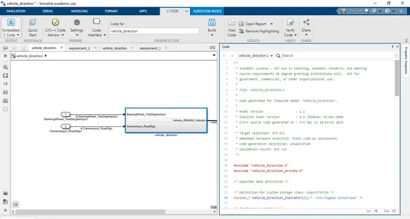 Also attached generated code.
MIL test:
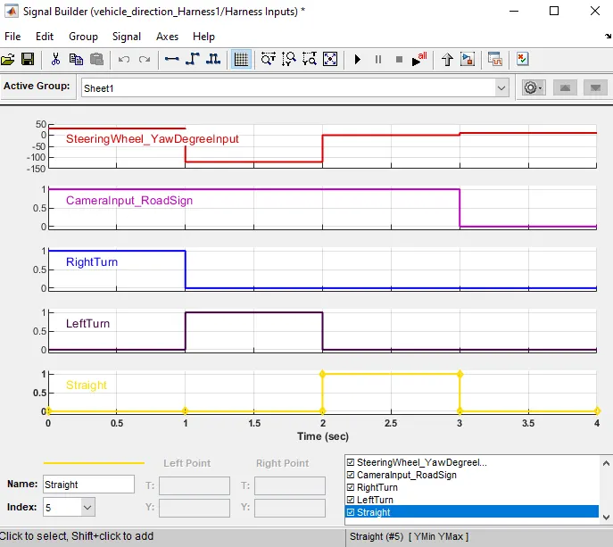
The MIL test is conducted for this model the input of the signal builder is shown below. The test case is created in an excel sheet.
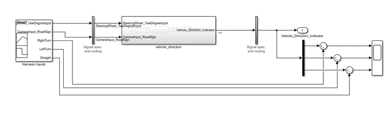
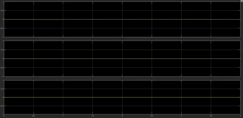
To verify the result sum block is added to find the difference between the input signal and the output signal.
The scope output is shown below.
SIL test:
Before performing the SIL test change the vehicle direction subsystem block parameter to treat it as an atomic unit. The test case is created in an excel sheet.
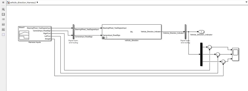
To verify the result sum block is added to find the difference between the input signal and the output signal.
The scope output is shown below.