Project 1 (Mini Project on Vehicle Direction Detection
- Aim: -
- To Build a Simulink model as per requirement document and create requirements tagging.
- To check a model under standard guidelines with help of model adviser. (MABB guidelines)
- To build an embedded code for model.
- Objective: -
- Development of MATLAB Simulink model as per requirement.
- Tag the requirements to the simulink model; tagging requirement 1 & requirement 2 to their corresponding subsystems is fine.
- MBD compliant changes, Data Dictionary creation & code generation is added advantage, and that is not scope of this project.
- When choosing code generation, Storage class for Input signals: ImportedExtern; Storage class for Output signal: Export to File; Storage class for local signals: localizable; Storage class for calibration signals: Const.
- Choose sample time for all signals as 0.01s
- Requirement Analysis Data: -
- Requirement - 1: -
- Steering wheel input as yaw rate (Signal name: SteeringWheel_YawDegreeInput) is the input for this system.
- This is compared against 3 angular values, one each for left turn, right turn & straight drive (Calibration Values: Right_Turn_AngularLimit, Left_Turn_AngularLimit, Straight_Drive_Steering_Angle) to say which specific direction the steering wheel is turning towards.
- Use switch blocks to compare & develop this requirement. Keep this requirement in a subsystem & output of this requirement is a local signal (Signal Name: Vehicle_Turn_Status).
- Requirement – 2: -
- Keep this requirement as a separate subsystem. Inputs to this requirement are local signal from requirement 1 (Signal Name: Vehicle_Turn_Status) & an input signal from camera (Signal Name: CameraInput_RoadSign), which confirms the occurrence of a road sign.
- Signal Vehicle_Turn_Status is compared against calibration values (Calibration Values: RightTurn_RoadSign, LeftTurn_RoadSign, Straight_RoadSign), if each of them is found equal, then each of the three corresponding output is compared against the camera input signal,
- Using a logical operator block, only one among them is finally given as output signal (Signal Name: Vehicle_Direction_Indicator).
- Signals & Calibration Data List:
|
Signal / Calibration Name |
Signal Type |
Data Type |
Dimension |
Min |
Max |
Initial Value |
Units |
|
SteeringWheel_YawDegreeInput |
Input |
Int16 |
1 |
-180 |
180 |
- |
Deg |
|
CameraInput_RoadSign |
Input |
Boolean |
1 |
0 |
1 |
- |
- |
|
Vehicle_Turn_Status |
Local |
Int16 |
1 |
-180 |
180 |
- |
Deg |
|
Right_Turn_AngularLimit |
Calibration |
Int16 |
[1 1] |
-180 |
180 |
30 |
Deg |
|
Left_Turn_AngularLimit |
Calibration |
Int16 |
[1 1] |
-180 |
180 |
-120 |
Deg |
|
Straight_Drive_Steering_Angle |
Calibration |
Int16 |
[1 1] |
-180 |
180 |
0 |
Deg |
|
RightTurn_RoadSign |
Calibration |
Int16 |
[1 1] |
-180 |
180 |
30 |
|
|
LeftTurn_RoadSign |
Calibration |
Int16 |
[1 1] |
-180 |
180 |
-120 |
|
|
Straight_RoadSign |
Calibration |
Int16 |
[1 1] |
-180 |
180 |
0 |
|
|
Vehicle_Direction_Indicator |
Output |
Boolean |
1 |
0 |
1 |
- |
- |
- Simulink model: -
- Requirement-1 subsystem: -
Here first we created a subsystem for our 1st requirement. For every requirement we have to generate a subsystem.
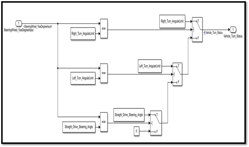
Blocks used: - inport, outport, constant, relational operator, switch.
- Took one subsystem named as requirement-1. inport block named as steering wheel yaw degree input.
- Now I compared input with three constants are Right_Turn_AngularLimit, Left_Turn_AngularLimit, Straight_Drive_Steering_Angle) with the help of relational operator block.
- If the relational operator's condition is true then we decide which input will go to execute with the help of switch block.
- Three switch blocks are used to decide which specific direction the steering wheel is turning towards.
- If the first comparison is true then the first switch true value will go for execution which is right turn.
- If the first switch value is false the second witch value will go to execution.
- If the second comparison is true then the second switch true value will go for execution which is left turn.
- If the second switch value is false the third witch value will go to execution.
- If the third comparison is true then third switch true value will go for execution which is straight drive.
- If the third switch value is false the second port value will go for execution which is 0.
- The vehicle turn status which is output signal was connected to outport vehicle_turn_status.
- Requirement-2 subsystem: -
Here first we created a subsystem for our 2nd requirement.
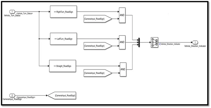
Blocks used: - inport, outport, compare to constant, logic operator, signal conversion, constant, goto, from.
- Took one subsystem named as requirement 2. inport for this subsystem is output signal from requirement 1 which is vehicle turn status.
- Now input Signal Vehicle_Turn_Statusis compared against calibration values RightTurn_RoadSign, LeftTurn_RoadSign, Straight_RoadSign.
- If the condition is true then we decide which input will go to execute with the help of and relation operator block.
- In the relation operator block if the both inputs Turn_RoadSign and Camerainput_roadsign are given value 1 then only the turn road sign given to merge block.
- Merge block used here to decide which value will go for execution. If the and block gives value 1 then only the merge block will give value to outport that is Vehicle_Direction_Indicator.
- The signal conversion block is used to signal conversion of merge block with edit parameter signal copy. Which means the same signal will go forward.
- If the first comparison is true then first and block value 1 will go for merge block which is right turn road sign.
- If AND block value is 0 (false) the second and block value will go to execution.
- If the second comparison is true then first and block value 1 will go for merge block which is left turn road sign.
- If AND block value is 0 (false) the third and block value will go to execution.
- If the third comparison is true then third and block value 1 will go for merge block which is straight drive road sign.
- The merge block will only get input from only on AND block at a time. So, the only one turn indicator signal will go at a time.
- Direction Detection model: -
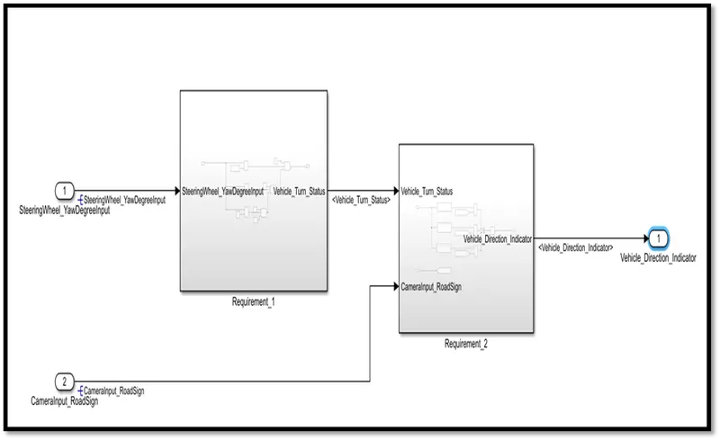
For the requairement_1 and requairement_2 inport, outprt are connected properly.
- SLDD file: -
1. To create SLDD file under modeling tan in design section there is one option link data dictionary. Click on that tab.
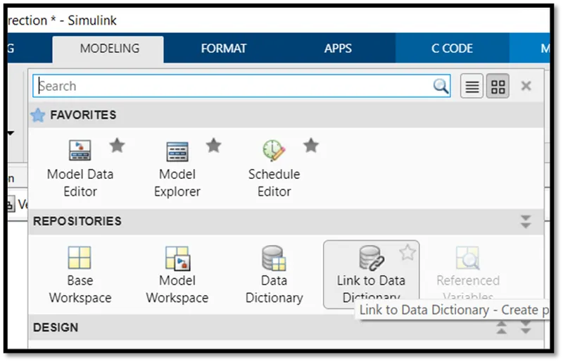
2. The new window will open for in that window click on new to create new file and create new file save this file in same directory.
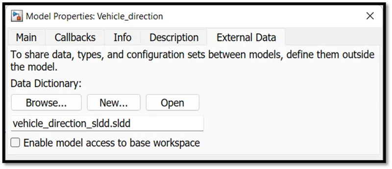
3. Now open this file and add all given signals and constant with all parameters.
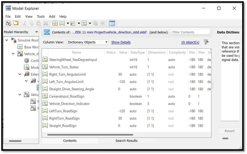
4. If you see it here, we can edit and save all parameters under one file.
5. No need to change parameter every time you open the model next time.
6. Once you save all parameters for variable in SLDD it will be saved until you use the file for model.
7. Also, you can use one SLDD file for more than one model.
- Code compiled model (non-virtual Subsystem): - (treat as atomic subsystem)
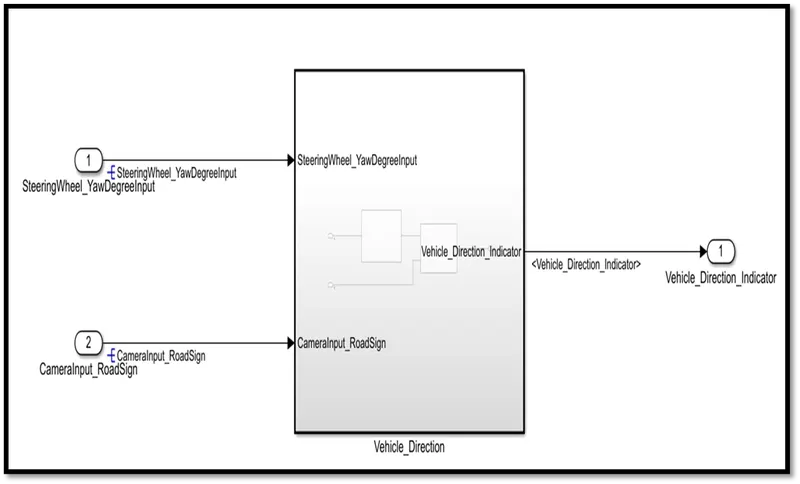
1. Now the most important thing we created whole Simulink model as atomic subsystem. For code generation we need to make sub systems as atomic.
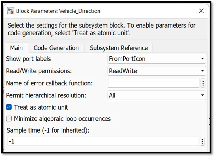
2. After Right click on subsystem in block parameter option we have to check the treat as atomic unit option.
- Signal resolve and propagation: -
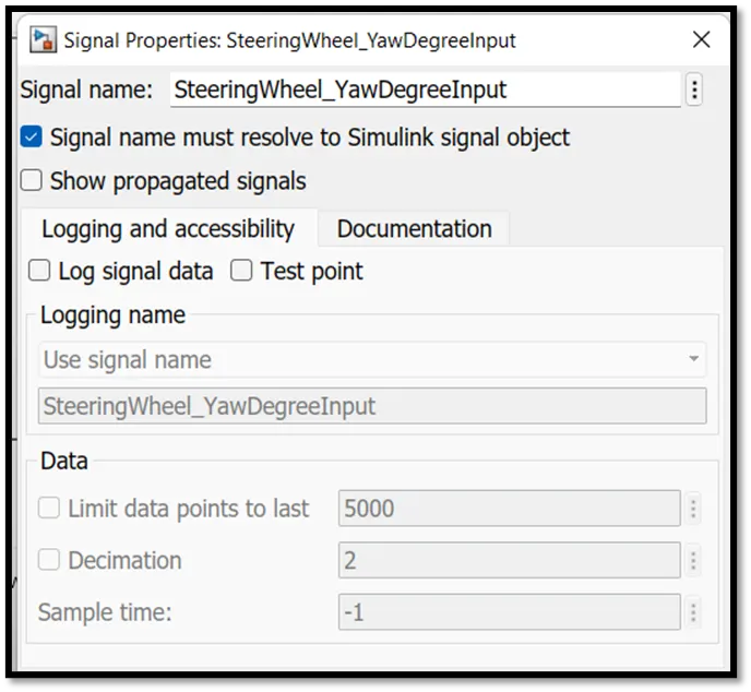
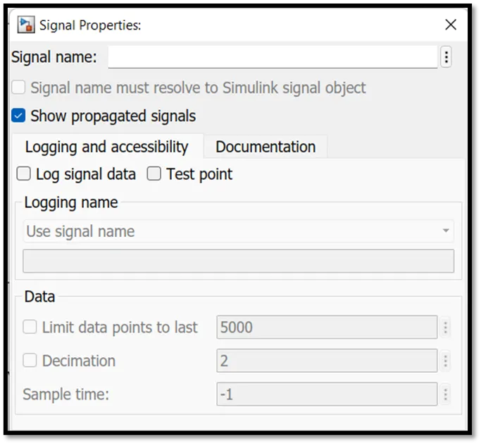
1. In signal properties you can resolve and propagate the signal.
2. If the signal is the first type to appear in the system you have to resolve otherwise propagate it.
3. Signal resolve and propagation is most important for code generation.
- Requirement tagging: -
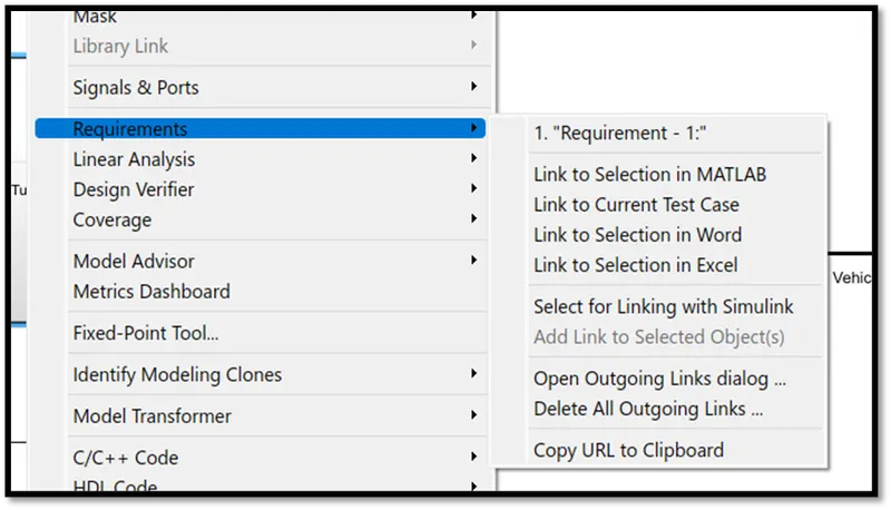
1. Requirement tagging is nothing but linking your requirement document to the model subsystem which is related to that requirement.
2. It is given advantage to understand the model when someone new is handling this file.
3. We done requirement tagging on right click on subsystem under requirement parameter you can tag the requirement.
4. First you have to select the requirement in requirement document to tag with related subsystem. Also, the file has to be saved in the same directory.
- Code generation settings: -
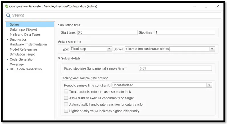
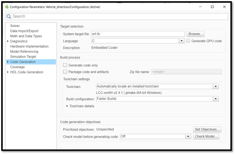
1. There are mainly two settings we have to do which are solver setting and code generation setting.
2. For code generation we can only use a fixed step solver.
3. As per requirement we change the solver setting to fix step discrete and fixed step time as 0.01 sec.
4. For embedded code generation in system target file will always ert.tlc which is embedded coder. Which generates embedded c code.
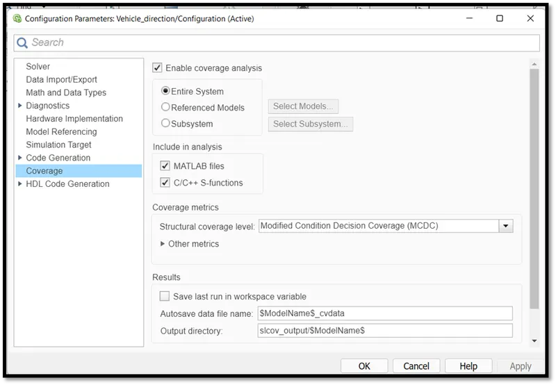
We can do coverage settings to check the execution of all blocks.
- MAAB guideline check: - (Model advisor)
1. Under the modelling tab there is a model adviser tab to check model with standard guidelines.
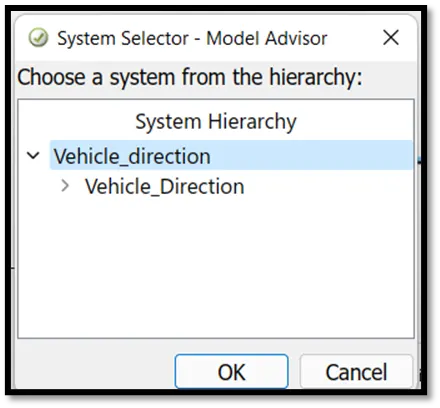
2. Tab on that tab this window will open to select model.
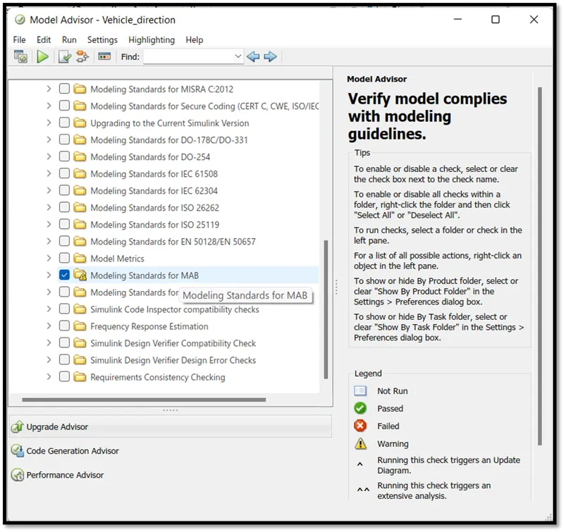
3. After selecting the model, the model adviser checked for the model first.
4. Then in the task option we have to select modelling standard for MAB. Then we have to select which guidelines we have to check.
5. Then run adviser check for selected checked guidelines.
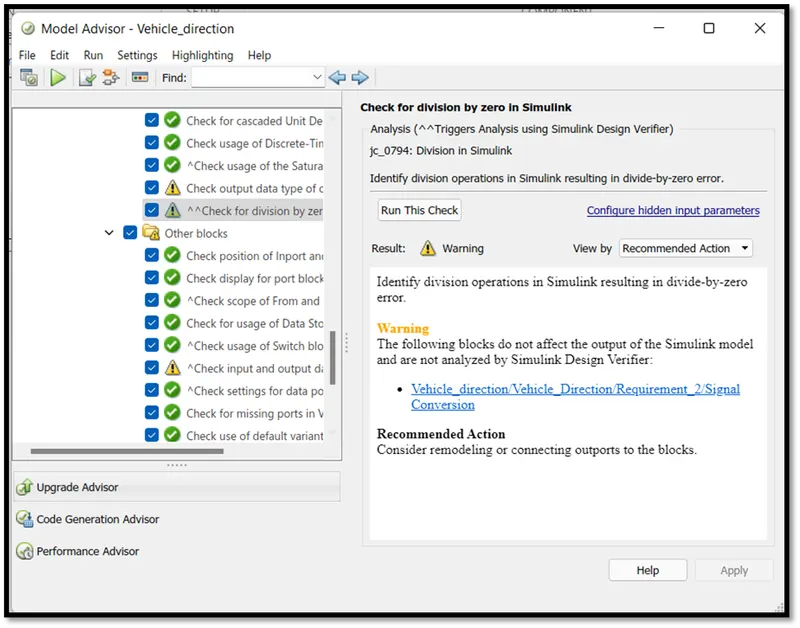
6. If some errors occur you can check for that under the MAB tab.
7. There are also some warnings. if its greater than requirement solve the warning and check again for that warning.
8. You can check for individual errors and warnings also.
9. If you are searching for a particular block in the system. You can click in report on any block it will take you to that block.
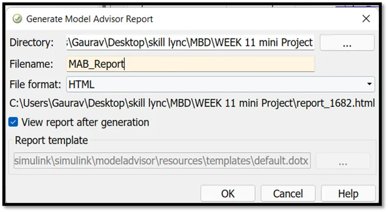
10. After checking all models with standard guidelines, you can generate a model adviser report.
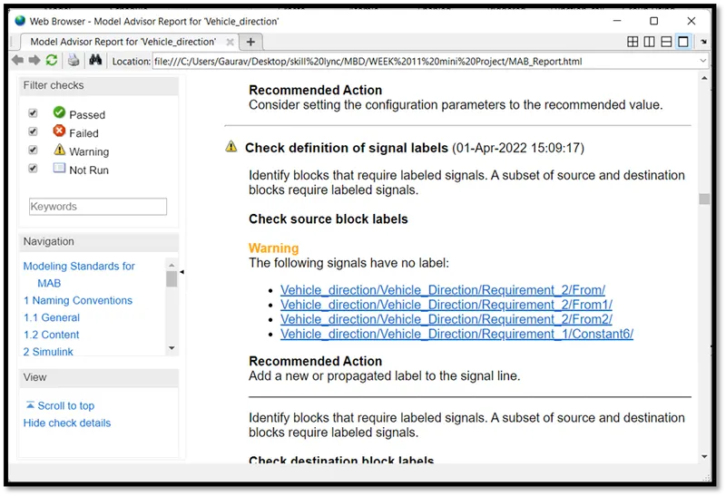
11. If click on any label highlighted in the report it will go directly to that particular model or signal.
- Code generation steps: -
1. It is a simple step if your model has no error according to MAAB guidelines then you are good to go for code generation.
2. In the tool bar under the app section there is embedded coder option.
3. In that option the build code option is there. Once click on that tab your code will generate.
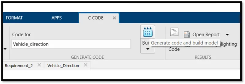
4. You can view your c code in view code tab on tool bar under code section.
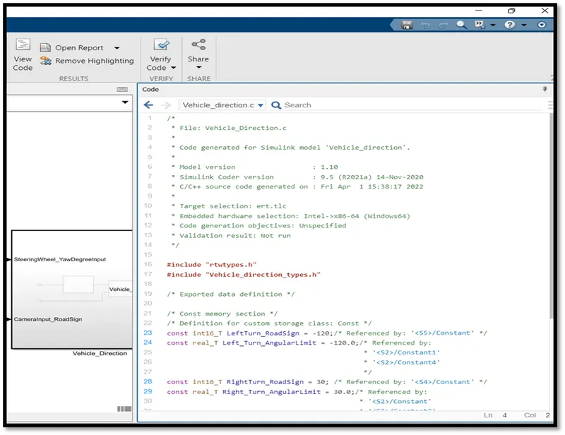
- code file: -
/*
 * File: Vehicle_Direction.c
 *
 * Code generated for Simulink model 'Vehicle_direction'.
 *
 * Model version                  : 1.10
 * Simulink Coder version         : 9.5 (R2021a) 14-Nov-2020
 * C/C++ source code generated on : Fri Apr  1 15:38:17 2022
 *
 * Target selection: ert.tlc
 * Embedded hardware selection: Intel->x86-64 (Windows64)
 * Code generation objectives: Unspecified
 * Validation result: Not run
 */

#include "rtwtypes.h"
#include "Vehicle_direction_types.h"

/* Exported data definition */

/* Const memory section */
/* Definition for custom storage class: Const */
const int16_T LeftTurn_RoadSign = -120;/* Referenced by: '<S5>/Constant' */
const real_T Left_Turn_AngularLimit = -120.0;/* Referenced by:
                                              * '<S2>/Constant1'
                                              * '<S2>/Constant4'
                                              */
const int16_T RightTurn_RoadSign = 30; /* Referenced by: '<S4>/Constant' */
const real_T Right_Turn_AngularLimit = 30.0;/* Referenced by:
                                             * '<S2>/Constant'
                                             * '<S2>/Constant3'
                                             */
const real_T Straight_Drive_Steering_Angle = 0.0;/* Referenced by:
                                                  * '<S2>/Constant2'
                                                  * '<S2>/Constant5'
                                                  */
const int16_T Straight_RoadSign = 0;   /* Referenced by: '<S6>/Constant' */

/*
 * File trailer for generated code.
 *
 * [EOF]
 */
All files for the codes are generated for model will automatically save in same directory.
- Conclusion: -
The code generation for model-based development is very easy compared to writing millions of codes. It will be possible with the right solver and code generation setting and mainly due to model adviser check for standard MAAB guidelines. Hence, we can conclude that with proper setting and standard guidelines it will be very easy to build a code for model. It will be a cost efficient and time saving method of design and development of model. It will be possible due to MATLAB. There is a lot of software for the same modelling environment but for better understanding and easy to use we can always prefer MATLAB.
Project files: -