Project 1 (Mini Project on Vehicle Direction Detection
Aim
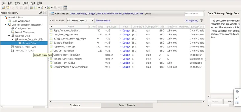
By using switch logic and subsytems, aim is to achieve the output indicating the right, left turn or straight drive of the vehicle. The signals and calibration parameters are defined in the sldd. where the initial values along with the unit, range and other configurations to be defined. Resolution of the signals and also signal propogation is achieved.
simulink model
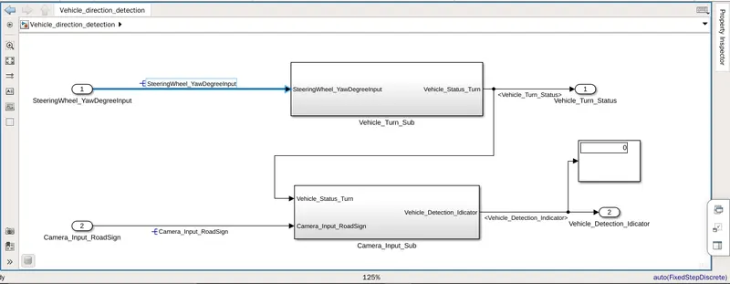
first subsytem compare the input SteeringWheel_YawDegreeInput with the calibration values as we can see in the below model
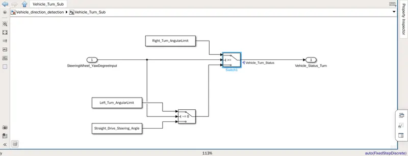
Switch block is used to swith between different caliration values. Output of the switch is localized signal which is then fed to the second subsystem.
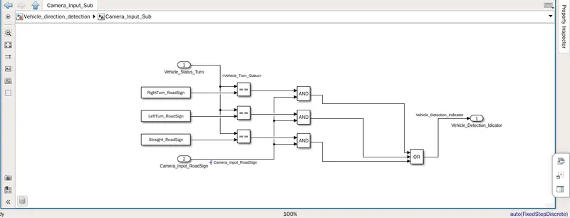
In the second subsystem the incomming localized signal is then compared with other calibration values for the sign board detection. Another camera input signal is also passed in the second subsystem as shown below.
SLDD Definition -
Output
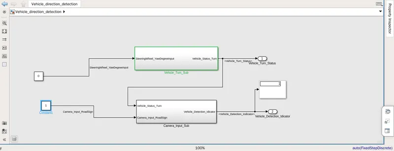
When the input is 0 output is one indicating the straight drive should be followed
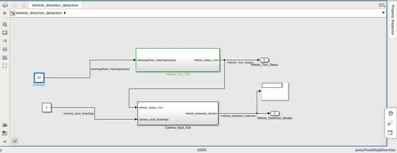
Similarly when input is greater than 30 vehicle should turn right shown by 1 boolean output signal.
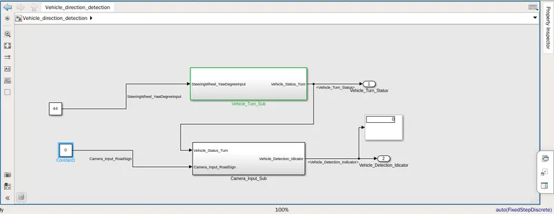
When the camera input is zero output is made 0 idicating desable turning signal.
simulink model file is attached below.