Project 1 (Mini Project on Vehicle Direction Detection
Objective: To identify the direction (Left turn, Right turn and Straight) based on the camera input and to determine whether car is going in correct direction or not. To develop the Simulink model according to requirements with SLDD according to MAAB guidelines and generate C code.
Steps:
- Create the SLDD(Simulink Data Dictionary) file which contains all input, output signals and constant parameters. To create this SLDD file;under modelling tab, first goto link to data dictionary and click on New and save it.
- In model explorer, to add input/output signals, click on simulink signal and to add calibration signals, click on simulink parameters. Change values according to requirement data as shown below:
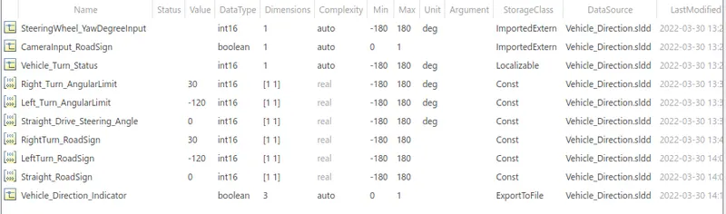
- Storage class for Input signals: ImportedExtern; Storage class for Output signal: Export to File; Storage class for local signals: localizable; Storage class for calibration signals: Const as shown below:
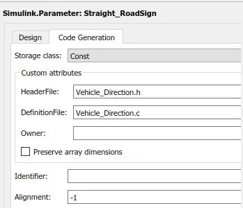
- Header file and Definition file are same for all signals to generate Code.
- Developed the Simulink model according to Requirements:
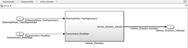
- Vehicle_Direction subsytem consist of Requirement-01 and Requirement-02 as shown below:

- Requirement-01:
- Steering wheel input as yaw rate (Signal name: SteeringWheel_YawDegreeInput) is the input for this system.
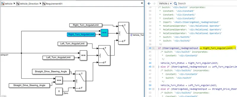
- This is compared against 3 angular values, one each for left turn, right turn & straight drive (Calibration Values: Right_Turn_AngularLimit, Left_Turn_AngularLimit, Straight_Drive_Steering_Angle) to say which specific direction the steering wheel is turning towards.
- Use switch blocks to compare & develop this requirement. Keep this requirement in a subsystem & output of this requirement is a local signal (Signal Name: Vehicle_Turn_Status).
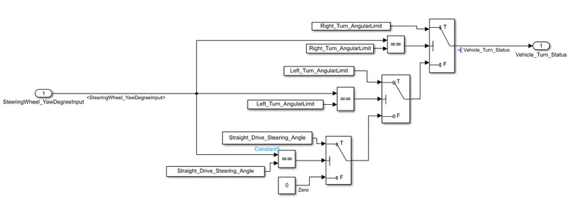
- Condition for switch block is Threshold or u2 ~= 0 according to MAAB guidelines.
- All signals are resolved and propogated with standard naming procedure.
- Tagged the this subsystem with Requirement-01 in word file.
- Requirement-02:
- Keep this requirement as a separate subsystem. Inputs to this requirement are local signal from requirement 1 (Signal Name: Vehicle_Turn_Status) & an input signal from camera (Signal Name: CameraInput_RoadSign), which confirms the occurrence of a road sign.
- Signal Vehicle_Turn_Status is compared against calibration values (Calibration Values: RightTurn_RoadSign, LeftTurn_RoadSign, Straight_RoadSign), if each of them is found equal, then each of the three corresponding output is compared against the camera input signal,
- Using a logical operator block, only one among them is finally given as output signal (Signal Name: Vehicle_Direction_Indicator).
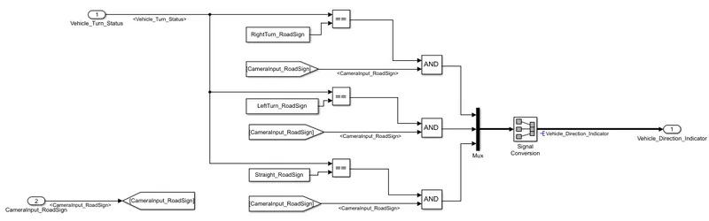
- All signals are resolved and propogated with standard naming procedure.
- Tagged the this subsystem with Requirement-02 in word file.
- Model Settings:
- under solver configuration, changed the solve type to fixed step with sample time of 0.01 secs.

- For code generation, select the system target file-ert.tlc which is Embedded coder.

- To Generate Advisor Report of MAAB;
- Under modelling tab, click on Model Advisor and from the hierarchy, choose the subsytem which consist of Requirement-01 and Requirement 02.
- Under task tab, select the modelling standards for MAB.
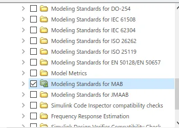
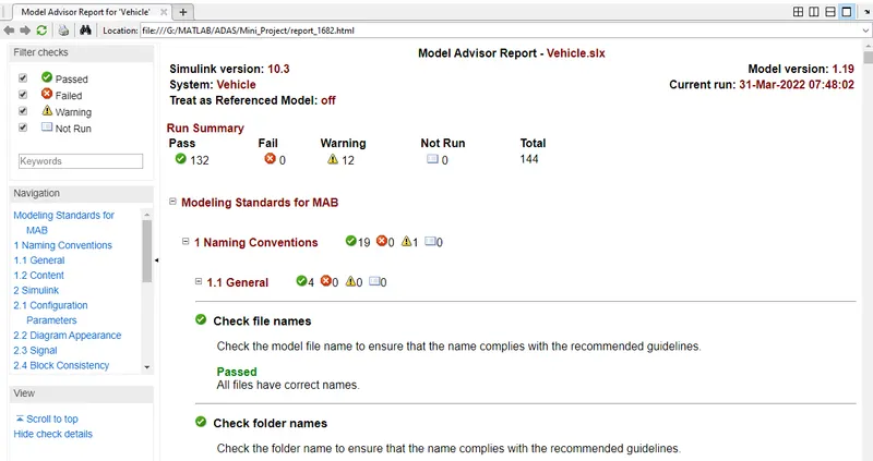
- Go for Run Selected Checks; it will show number of pass tests, fail tests and warning in summary.
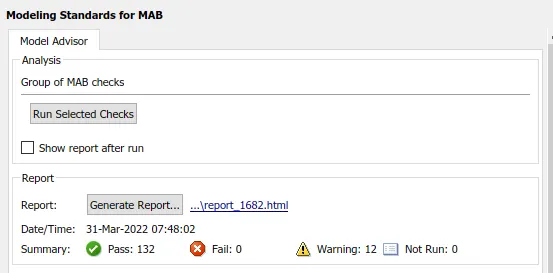
- Then Generate Report, to check all warning and errors in detail. We can also save this Report in desired format, directory.
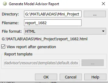
- Report in html format.
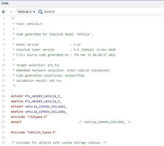
- For code generation, goto apps than embedded coder, click on build option. Code will generate as shown below:
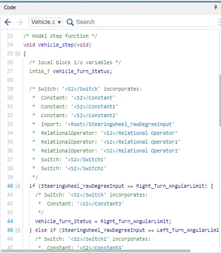
- we can trace our code with model also, by clicking on variables.
Conclusions:
- Simulink model is made according to requirements with SLDD.
- Model advisor Report of MAB is generated with 132 pass tests, zero error and 12 warnings.
- Requirement Tagging is done.
- C code is generated according to Requirements.