Project 1 (Mini Project on Vehicle Direction Detection
MINI PROJECT
VEHICLE DIRECTION DETECTION
AIM:-
Identifying the direction of the vehicle based on the camera input.
General Overview:-
Identifying the direction of the vehicle is one of the important & diverse features in Autonomous driving & Advanced Driver Assistance Features. This particular sub-feature of identifying the direction of the vehicle is identifying the direction the vehicle is taking based on the camera input.
The camera reads the road signs & stores them into its memory with unique values for a left turn, right turn & straight drive. Depending on the direction it is taking, the final indication is given to the driver – as an indication if he is driving in the recommended direction or not.
Vehicle Direction Determination can also be coupled alongside features like GPS systems to identify whether the vehicle is reaching its destination in an optimized manner. This sub-feature can also be used along with Lane Detection, Highway Warning, Ramp Entry / Exit in Wrong Way Detection, etc.
The objective of Project:-
- Development of MATLAB Simulink model as per requirement.
- Tag the requirements to the Simulink model; tagging requirement 1 & requirement 2 to their corresponding subsystems is fine.
- MBD compliant changes, Data Dictionary creation & code generation is added advantage, and that is not the scope of this project.
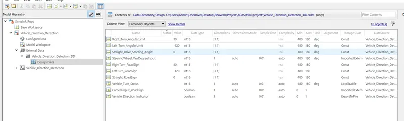
- If choosing code generation, Storage class for Input signals: ImportedExtern; Storage class for Output signal: Export to File; Storage class for local signals: localizable; Storage class for calibration signals: Const.
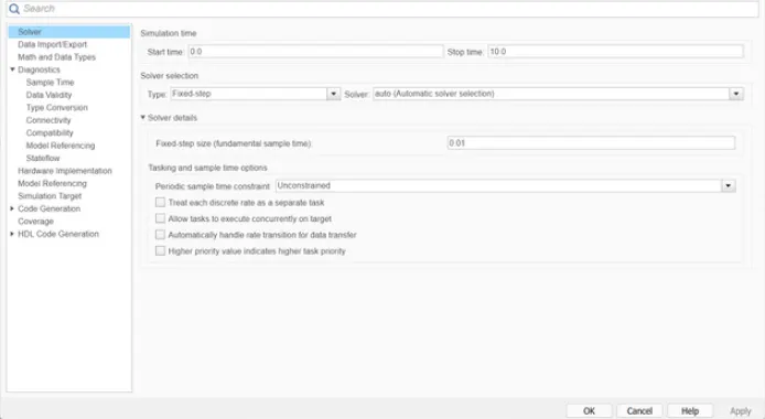
- Choose sample time for all signals as 0.01s.
Requirement Of Project:-
Requirement - 1:-
- Steering wheel input as yaw rate (Signal name: SteeringWheel_YawDegreeInput) is the input for this system.
- This is compared against 3 angular values, one each for a left turn, right turn & straight drive (Calibration Values: Right_Turn_AngularLimit, Left_Turn_AngularLimit, Straight_Drive_Steering_Angle) to say which specific direction the steering wheel is turning towards.
- Use switch blocks to compare & develop this requirement. Keep this requirement in a subsystem & the output of this requirement is a local signal (Signal Name: Vehicle_Turn_Status).
Requirement – 2:-
- Keep this requirement as a separate subsystem. Inputs to this requirement are a local signal from requirement 1 (Signal Name: Vehicle_Turn_Status) & an input signal from the camera (Signal Name: CameraInput_RoadSign), which confirms the occurrence of a road sign.
- Signal Vehicle_Turn_Status is compared against calibration values (Calibration Values: RightTurn_RoadSign, LeftTurn_RoadSign, Straight_RoadSign), if each of them is found equal, then each of the three corresponding output is compared against the camera input signal,
- Using a logical operator block, only one among them is finally given as output signal (Signal Name: Vehicle_Direction_Indicator).
Signals & Calibration Data List:-
|
Signal / Calibration Name |
Signal Type |
Data Type |
Dimension |
Min |
Max |
Initial Value |
Units |
|
SteeringWheel_YawDegreeInput |
Input |
Int16 |
1 |
-180 |
180 |
- |
Deg |
|
CameraInput_RoadSign |
Input |
Boolean |
1 |
0 |
1 |
- |
- |
|
Vehicle_Turn_Status |
Local |
Int16 |
1 |
-180 |
180 |
- |
Deg |
|
Right_Turn_AngularLimit |
Calibration |
Int16 |
[1 1] |
-180 |
180 |
30 |
Deg |
|
Left_Turn_AngularLimit |
Calibration |
Int16 |
[1 1] |
-180 |
180 |
-120 |
Deg |
|
Straight_Drive_Steering_Angle |
Calibration |
Int16 |
[1 1] |
-180 |
180 |
0 |
Deg |
|
RightTurn_RoadSign |
Calibration |
Int16 |
[1 1] |
-180 |
180 |
30 |
|
|
LeftTurn_RoadSign |
Calibration |
Int16 |
[1 1] |
-180 |
180 |
-120 |
|
|
Straight_RoadSign |
Calibration |
Int16 |
[1 1] |
-180 |
180 |
0 |
|
|
Vehicle_Direction_Indicator |
Output |
Boolean |
1 |
0 |
1 |
- |
- |
Theory:-
- The ultimate goal of ADAS feature development is to make our roads safer and better suited for fully autonomous vehicles in the long run. Still, manufacturers and buyers shouldn’t underestimate the importance of ADAS for meeting current automotive challenges. The most significant impact of advanced driver assistance systems is in providing drivers with essential information and automating difficult and repetitive tasks. This increases safety for everyone on the road.
- ADAS vision systems and ADAS safety systems require lots of fused sensors to monitor the vehicle’s surroundings and what’s going on inside the car.
- The most commonly used ADAS sensors today are lidar, radar, and ultrasonic. Software for self-driving cars featuring ultrasonic sensors usually consists of multiple sensors located in the front and rear bumpers and side-view mirrors.
- They transmit short sound waves and measure the time it takes for them to travel to a target object and return to the receiver.
- An ADAS safety system can rely on ultrasonic sensor technology for low-speed and short-range applications such as blind-spot detection, self-parking, and parking assistance.
- Radar and lidar are both used by ADAS engineers for object detection, collision prevention, and interaction with traffic management systems.
- Still, there are differences between these technologies. Lidar is the best solution for real-time detection, but it’s unpleasantly expensive for mass deployment.
- Radar sensors, especially long-range ones, are reliable enough and cheaper but lack precision when detecting small objects.
Simulink Model:-
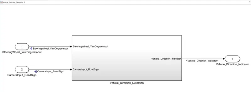
This is the main model subsystem that has two inputs SteeringWheel_YawDegreeInput and CameraInput_RoadSign entering into the Vehicle_Direction_Detection subsystem and one output Vehicle_Direction_Indicator.
Two requirements are designed in two separate subsystems.
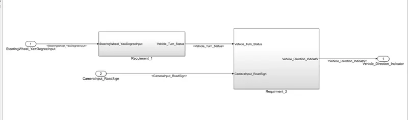
Requirment_1:-
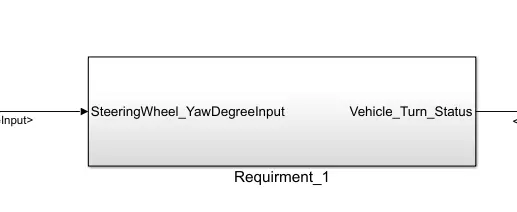
Above is the subsystem for the requirment_1 we need to hide the content preview of the subsystem as per the model-based development guidelines.
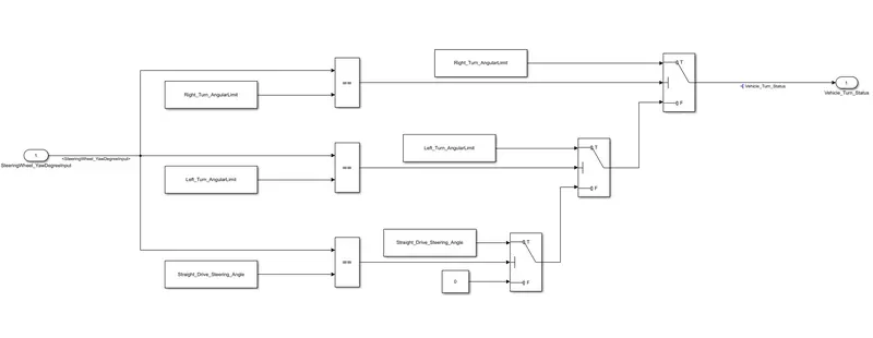
Inside this subsystem, there is our logic for requirement 1
- Steering wheel input as yaw rate (Signal name: SteeringWheel_YawDegreeInput) is the input for this system.
- This is compared against 3 angular values, one each for a left turn, right turn & straight drive (Calibration Values: Right_Turn_AngularLimit, Left_Turn_AngularLimit, Straight_Drive_Steering_Angle) to say which specific direction the steering wheel is turning towards.
- For comparing steering wheel input as yaw rate with the calibration values of for reach left, right, straight drive we used the relational operator '==' This is now compared against three angular values to say which specific direction the steering wheel is turning towards.
- In this case, the output of the relational operator '==' is equal to 1 only when the 'SteeringWheel_YawDegreeInput' matches the calibration value angular limit specified in Right_Turn_AngularLimit, Left_Turn_AngularLimit, or Straight_Drive_Steering_Angle.
- If the values of SteeringWheel_YawDegreeInput == Right_Turn_AngularLimit, Left_Turn_AngularLimit, or Straight_Drive_Steering_Angle then it will show the output in boolean as 1.
- Three switch blocks are used for the if-else statement. To the first input port (Input 1) of the switch block calibration block is connected and after that to the second input block (input 2) output from the relational operator block is connected it is given as the condition input to the switch block. The switch will pass input1 (calibration value) when the condition (input2~=0) condition is satisfied, else input3 (output from the next switch block) is passed as output.
- The signal 'Vehicle_Turn_Status' obtained at the output of the first switch will be a calibration angular value (Right_Turn_AngularLimit OR Left_Turn_AngularLimit, OR Straight_Drive_Steering_Angle). If none of the conditions get satisfied, zero is passed as the output from the last switch. The signal 'Vehicle_Turn_Status' is fed to the outport of subsystem 'Requirement1'.
Requirment_2:-
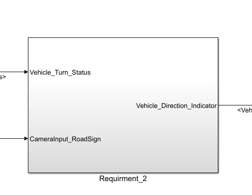
Above is the Requirment_2 subsystem inside this subsystem we have the camera input and our requirement 1 logic this is the input for the requirement_2 Subsystem. And Vehicle_Direction_Indicator is the output for this subsystem.
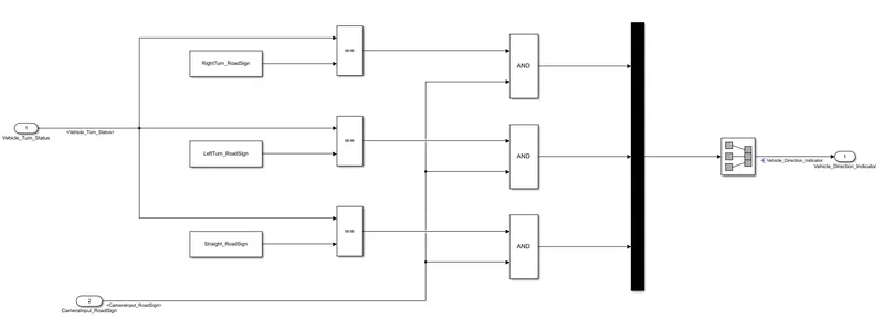
- Keep this requirement as a separate subsystem. Inputs to this requirement are a local signal from requirement 1 (Signal Name: Vehicle_Turn_Status) & an input signal from the camera (Signal Name: CameraInput_RoadSign), using the relational operator '==', which confirms the occurrence of a road sign.
- Signal Vehicle_Turn_Status is compared against calibration values (Calibration Values: RightTurn_RoadSign, LeftTurn_RoadSign, Straight_RoadSign), if each of them is found equal, then each of the three corresponding outputs is compared against the camera input signal. Which confirms the occurrence of a road sign using AND Operator.
- Using a logical operator block, only one among them is finally given as output signal (Signal Name: Vehicle_Direction_Indicator). The boolean output signal obtained from each of the three 'AND' blocks is fed to the outport 'Vehicle_Direction_Indicator' to indicate the vehicle direction. The output 'Vehicle_Direction_Indicator' will be a three-dimension signal having three boolean elements, with the first element to indicate 'Right Turn', the second element to indicate 'Left Turn', and the third element to indicate 'Straight Drive'.
Requirement Tagging Of Simulink Model:-
all the requirements are tagged for better understandability, anyone who is reviewing the model or who is trying to update the model can get a clear idea of what logic is used in the system. from the requirement manager, we can see what are all are tagged and the description.
1)Firstly I wrote all requirements in a word file then I select my first requirement then I return to the model selected my first subsystem to right-click on it then goto requirements and link to selection in word then my subsystem box is highlighted and linked. in this way, I link my second subsystem with requirement 2.
Requirement 1 Tagging with Subsystem 1:-
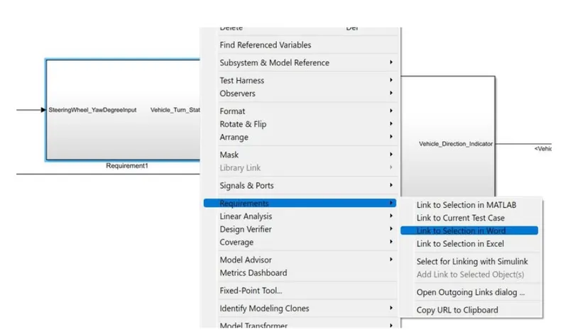
Requirement 1 Tagging with Subsystem 1:-
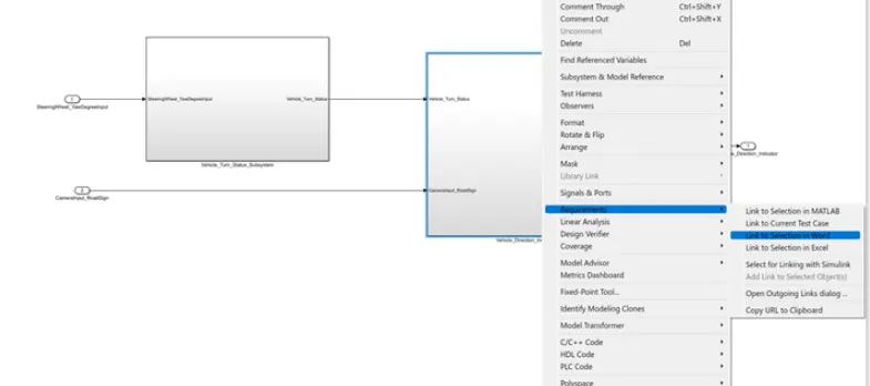
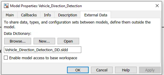
Creation of SLDD:-
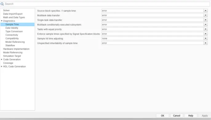
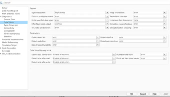
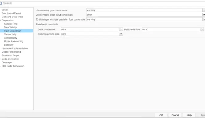
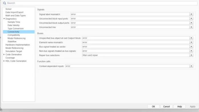
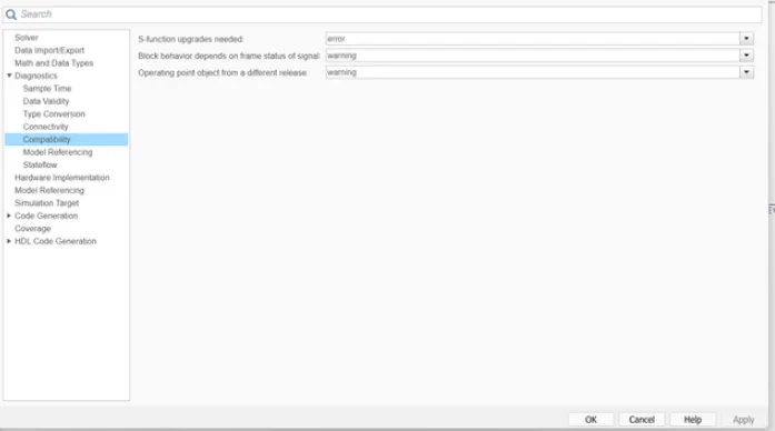
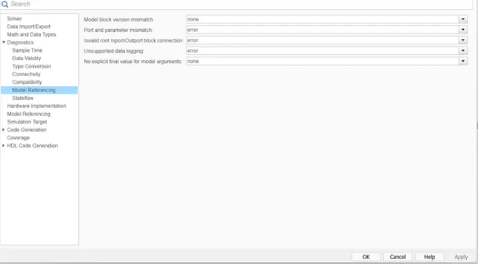
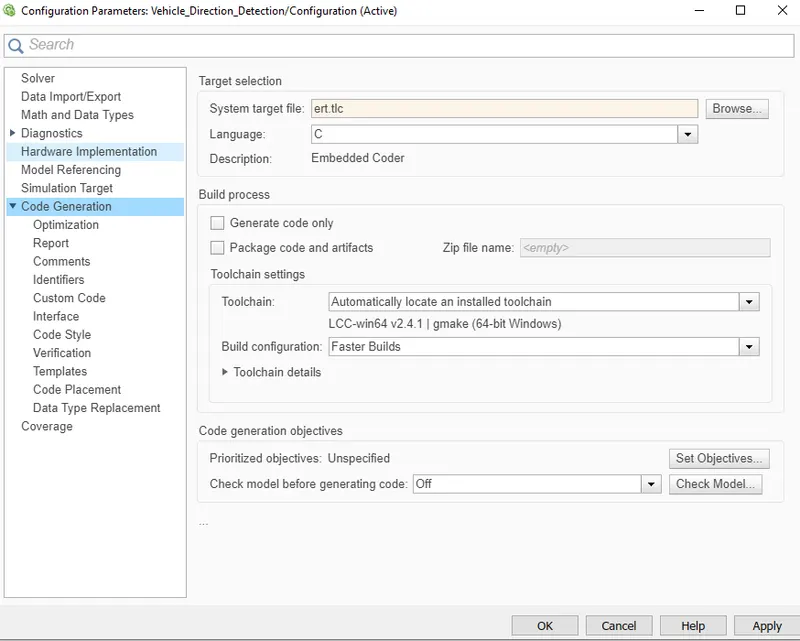
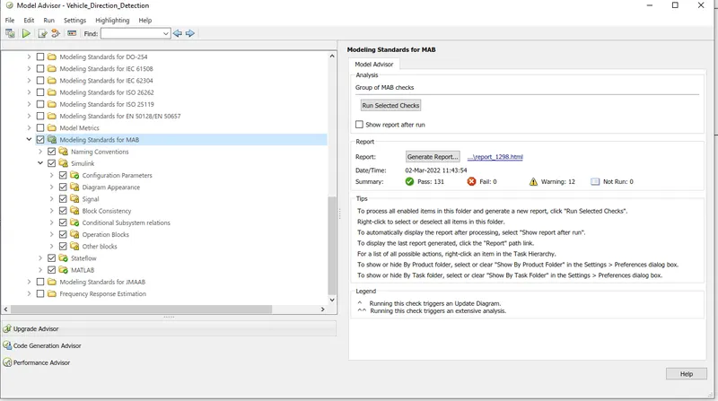
MODEL ADVISORY REPORT:-
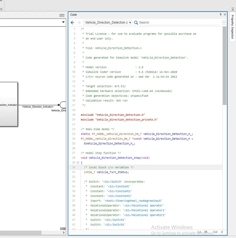
/*
 * Trial License - for use to evaluate programs for possible purchase as
 * an end-user only.
 *
 * File: Vehicle_Direction_Detection.c
 *
 * Code generated for Simulink model 'Vehicle_Direction_Detection'.
 *
 * Model version                  : 1.5
 * Simulink Coder version         : 9.5 (R2021a) 14-Nov-2020
 * C/C++ source code generated on : Wed Mar  2 11:54:34 2022
 *
 * Target selection: ert.tlc
 * Embedded hardware selection: Intel->x86-64 (Windows64)
 * Code generation objectives: Unspecified
 * Validation result: Not run
 */

#include "Vehicle_Direction_Detection.h"
#include "Vehicle_Direction_Detection_private.h"

/* Real-time model */
static RT_MODEL_Vehicle_Direction_De_T Vehicle_Direction_Detection_M_;
RT_MODEL_Vehicle_Direction_De_T *const Vehicle_Direction_Detection_M =
  &Vehicle_Direction_Detection_M_;

/* Model step function */
void Vehicle_Direction_Detection_step(void)
{
  /* local block i/o variables */
  int16_T Vehicle_Turn_Status;

  /* Switch: '<S2>/Switch' incorporates:
   *  Constant: '<S2>/Constant'
   *  Constant: '<S2>/Constant1'
   *  Constant: '<S2>/Constant2'
   *  Inport: '<Root>/SteeringWheel_YawDegreeInput'
   *  RelationalOperator: '<S2>/Relational Operator'
   *  RelationalOperator: '<S2>/Relational Operator1'
   *  RelationalOperator: '<S2>/Relational Operator2'
   *  Switch: '<S2>/Switch1'
   *  Switch: '<S2>/Switch2'
   */
  if (SteeringWheel_YawDegreeInput == Right_Turn_AngularLimit) {
    /* Switch: '<S2>/Switch' incorporates:
     *  Constant: '<S2>/Constant3'
     */
    Vehicle_Turn_Status = Right_Turn_AngularLimit;
  } else if (SteeringWheel_YawDegreeInput == Left_Turn_AngularLimit) {
    /* Switch: '<S2>/Switch1' incorporates:
     *  Constant: '<S2>/Constant4'
     *  Switch: '<S2>/Switch'
     */
    Vehicle_Turn_Status = Left_Turn_AngularLimit;
  } else if (SteeringWheel_YawDegreeInput == Straight_Drive_Steering_Angle) {
    /* Switch: '<S2>/Switch2' incorporates:
     *  Constant: '<S2>/Constant5'
     *  Switch: '<S2>/Switch'
     *  Switch: '<S2>/Switch1'
     */
    Vehicle_Turn_Status = Straight_Drive_Steering_Angle;
  } else {
    /* Switch: '<S2>/Switch' incorporates:
     *  Constant: '<S2>/Constant6'
     *  Switch: '<S2>/Switch1'
     *  Switch: '<S2>/Switch2'
     */
    Vehicle_Turn_Status = 0;
  }

  /* End of Switch: '<S2>/Switch' */

  /* SignalConversion: '<S3>/Signal Copy' incorporates:
   *  Constant: '<S3>/Constant'
   *  Constant: '<S3>/Constant1'
   *  Constant: '<S3>/Constant2'
   *  Inport: '<Root>/CameraInput_RoadSign'
   *  Logic: '<S3>/AND'
   *  Logic: '<S3>/AND1'
   *  Logic: '<S3>/AND2'
   *  RelationalOperator: '<S3>/Relational Operator'
   *  RelationalOperator: '<S3>/Relational Operator1'
   *  RelationalOperator: '<S3>/Relational Operator2'
   */
  Vehicle_Direction_Indicator[0] = ((Vehicle_Turn_Status == RightTurn_RoadSign) &&
    CameraInput_RoadSign);
  Vehicle_Direction_Indicator[1] = ((Vehicle_Turn_Status == LeftTurn_RoadSign) &&
    CameraInput_RoadSign);
  Vehicle_Direction_Indicator[2] = ((Vehicle_Turn_Status == Straight_RoadSign) &&
    CameraInput_RoadSign);
}

/* Model initialize function */
void Vehicle_Direction_Detection_initialize(void)
{
  /* (no initialization code required) */
}

/* Model terminate function */
void Vehicle_Direction_Detection_terminate(void)
{
  /* (no terminate code required) */
}

/*
 * File trailer for generated code.
 *
 * [EOF]
 */
CONCLUSION:-