Project 1 (Mini Project on Vehicle Direction Detection
AIM:
- In this Project, Vehicle Turn Status is detected and also the turn indication is given using camera input.
- Two subsystems is used one is to vechicle turn status and another one is to give indication.
- To create a Simulink Data Dictionary and a Simulink Model accorrding to the given Requirement.
MODEL:
- Vehicle turn status subsystem:
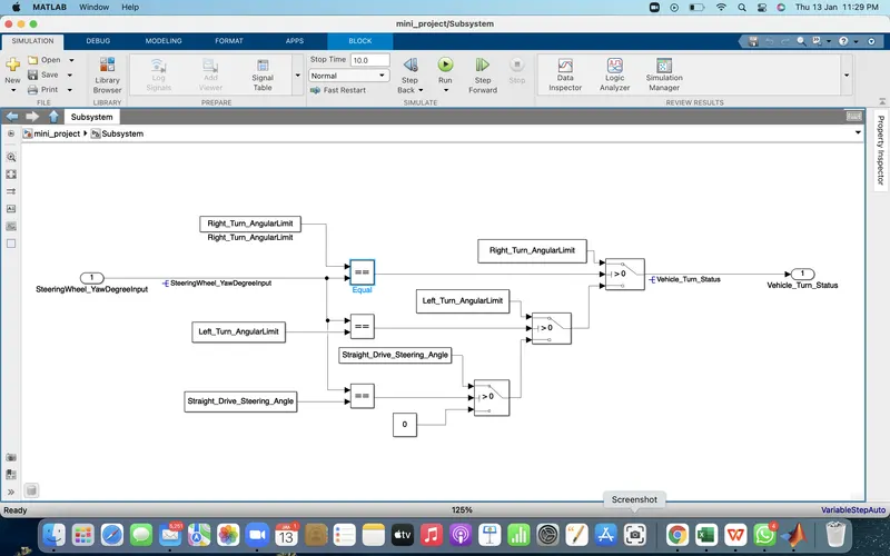
- Input for this system is from the steering it is named in the model as ' SteeringWheel_YawDegreeInput' .
- Input is inter checked with Right turn angular limit,Left turn angular limit,straight drive angle using Equal Relational operator.
- Three switch's were used, each swich conditon input is connected from the output of equal block of respective angular constant.
- For example if the given steering angle is -120 it will be checked with the each angular constants and left turn angular constant is equal,then the output of respective equal block gives the value '1' to the conditioning input of the respective switch and the switch will give the true condition as output.which is left turn angular limit for this example.
- The screenshot of this system is attached below.
- Vechicle Direction Indication:
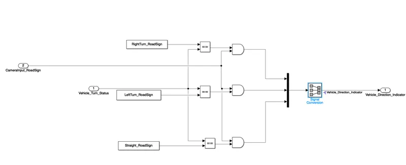
- Input of this subsytem is 'Vehicle Turn Status' and 'Camera input' .
- Vehicle Turn Status is compared with Right turn road sign,Left turn road sign and straight road sign.
- Using relational equal to operator.
- Camera Input and Output from equal blocks is given as a input to the three AND logic operator.
- Output signals from each AND gate is given to the mux block.
- Mux output is given to Signal conversion block where we get the Final output Vehicle Direction Indication.
- Below the screenshot of the subsystem is attached.
Result:
- The given signal values and constant values are created as a Data Dictinory named Vechicle direction indication.
- The storage classes are feeded as mentioned.
- The SIL operation is not done because of Trail version.so the steps to create it is mentioned below.
- Click(Subsystem)->Test Harness->Advanced Properties->Software in loop->Ok
- The the code will be generated for the system.
- Below , The Data Dictionary file and simulink model is attached.